SICK Bluetooth WLA16 User manual

Described product
WLA16
Manufacturer
SICK AG
Erwin-Sick-Str. 1
79183 Waldkirch
Germany
Legal information
This work is protected by copyright. Any rights derived from the copyright shall be
reserved for SICK AG. Reproduction of this document or parts of this document is only
permissible within the limits of the legal determination of Copyright Law. Any modifica‐
tion, abridgment or translation of this document is prohibited without the express writ‐
ten permission of SICK AG.
The trademarks stated in this document are the property of their respective owner.
© SICK AG. All rights reserved.
Original document
This document is an original document of SICK AG.
2006/42/EC
NO
SAFETY
28020348.14CS | SICK
Subject to change without notice

Contents
1 Safety information............................................................................ 4
1.1 General safety notes................................................................................ 4
1.2 Notes on UL approval............................................................................... 4
2 Intended use...................................................................................... 4
3 Operating elements and status indicators.................................... 4
4 Mounting............................................................................................. 5
5 Electrical installation........................................................................ 5
6 Additional functions.......................................................................... 7
7 Commissioning.................................................................................. 8
8 Process data structure..................................................................... 11
9 Troubleshooting................................................................................. 11
10 Disassembly and disposal............................................................... 12
11 Maintenance...................................................................................... 12
12 Technical data.................................................................................... 12
12.1 Dimensional drawings.............................................................................. 13
CONTENTS
8020348.14CS | SICK
Subject to change without notice 3

1 Safety information
1.1 General safety notes
■Read the operating instructions before commissioning.
■
Connection, mounting, and configuration may only be performed by trained
specialists.
■
2006/42/EC
NO
SAFETY
Not a safety component in accordance with the EU Machinery Directive.
■
When commissioning, protect the device from moisture and contamination.
■These operating instructions contain information required during the life cycle of
the sensor.
1.2 Notes on UL approval
The device must be supplied by a Class 2 source of supply.
UL Environmental Rating: Enclosure type 1
2 Intended use
The WLA16 is an opto-electronic photoelectric retro-reflective sensor (referred to as
“sensor” in the following) for the optical, non-contact detection of objects, animals, and
persons. A reflector is required for this product to function. If the product is used for any
other purpose or modified in any way, any warranty claim against SICK AG shall become
void.
3 Operating elements and status indicators
WLA16x-xxxxxx00 WLA16x-xxxxxx01 WLA16x-xxxxxx02
1
2
3
1
23
5
1
23
4
1BluePilot blue: alignment aid
2LED indicator yellow: status of received light beam
3LED indicator green: supply voltage active
4Press-turn element: time function adjustment
5Teach pushbutton: adjustment of light/dark switching
1 SAFETY INFORMATION
48020348.14CS | SICK
Subject to change without notice

4 Mounting
Mount the sensor and the reflector using suitable mounting brackets (see the SICK
range of accessories). Align the sensor and reflector with each other.
Note the sensor's maximum permissible tightening torque of < 1,3 Nm.
5 Electrical installation
The sensors must be connected in a voltage-free state. The following information must
be observed, depending on the connection type:
– Male connector connection: Note pin assignment
– Cable: wire color
Only supply/switch on the voltage once all electrical connections have been estab‐
lished.
Explanations on connection diagram (table 1 - table 6)
Alarm = alarm output
Health = alarm output
MF (pin 2 configuration) = external input, teach-in, switching signal
QL1/C = switching output, IO-Link communication
Test = test input
UB: 10 ... 30 V DC
Table 1: Connections
Wxx16x- x4 xH x5 xI
1 = BN
2 = WH
3 = BU
4 = BK
5= GY
12
4 3
0.14 mm2
AWG26
12
5
4 3
0.14 mm2
AWG26
Wxx16x- x9 xB
1 = BN
2 = BU
3 = not connected
4 = BK
5= WH
6 = GY
7 = not connected
3 4
1
2 5
6
IN = 4 A
3
7
2
16
5
4
IN = 6 A
MOUNTING 4
8020348.14CS | SICK
Subject to change without notice 5

Table 2: DC
WLA16
x-
xx16XxxxA00 xx16Xx
xxA01-
A99
xx161 xx162 xx163 xx165 xx168 xx16A xx16L xx16N xx16x
1 = BN + (L+)
2 = WH MF
3 = BU - (M)
4 = BK QL1/C
Default:
MF
QQAlarm Alarm Test →
L+
no func‐
tion
Test →
L+
no func‐
tion
www.sic
k.com
80227
09
Default:
QL1/C
QQQQQ Q Q Q www.sic
k.com
80227
09
Table 3: DC
WLA16x- xxXXXxxxZZZ
xx111 xx112 xx114 xx116 xx421 xx422 xx721 xx722
BN + (L+)
WH QQHealth Health Q QQQ
BU - (M)
BK QQQQQQQQ
GR - - - - Test → L
+
Test → L
+
Test →
M
Test →
M
Table 4: Push/pull
Q
Push-pull
(≤ 100 mA)
+ (L+)
Q
‒ (M)
+ (L+)
Q
‒ (M)
Q
Push-pull
(≤ 100 mA)
+ (L+)
Q
‒ (M)
+ (L+)
Q
‒ (M)
5 ELECTRICAL INSTALLATION
68020348.14CS | SICK
Subject to change without notice

6 Additional functions
Alarm
Alarm output: The sensor (WLA16) features a pre-failure notification output (“Alarm” in
connection diagram table 5), which issues a notification if the sensor is only ready for
operation to a limited extent. The LED indicator flashes in this case. Possible causes:
Sensor or reflector is contaminated, sensor is out of alignment. In the good state: LOW
(0), if excessively contaminated HIGH (1).
Health
Health output: The sensor (WLA16) features a pre-failure notification output (“Health”
in connection diagram [see table 5]), which issues a notification if the sensor is only
ready for operation to a limited extent or the cable has been interrupted. Possible
causes: Sensor or reflector is contaminated, sensor is out of alignment, cable is dam‐
aged. In the good state: HIGH (1), if excessively contaminated or in the event of cable
interruption LOW (0). The yellow LED indicator flashes in this case.
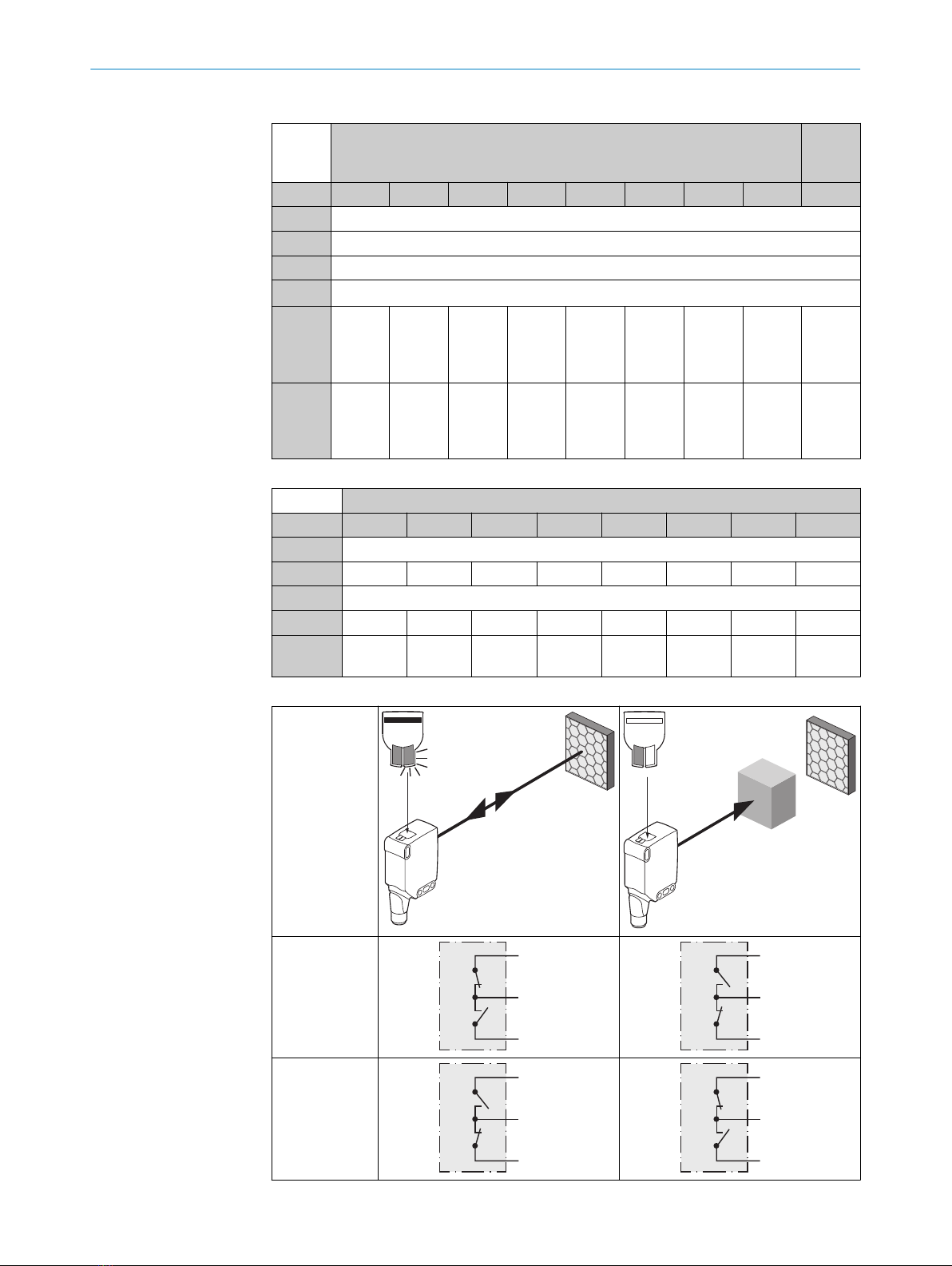
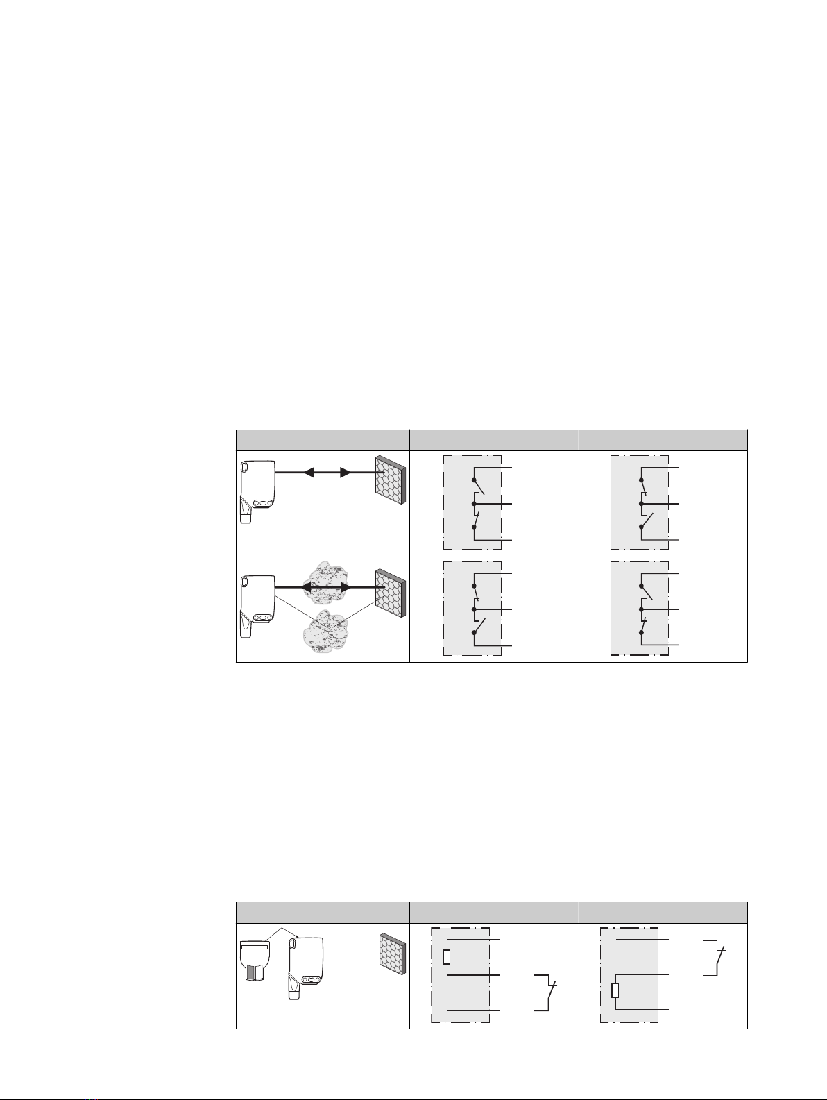
Table 5: Alarm / Health
Alarm (≤ 100 mA) Health (≤100 mA)
+ (L+)
Alarm
‒ (M)
+ (L+)
Health
‒ (M)
+ (L+)
Alarm
‒ (M)
+ (L+)
Health
‒ (M)
Test input
Test input: The WLA16 sensors feature a test input (“TI” or “Test” on the connection
diagram [see table 2, table 3 and table 6]), which can be used to switch the sender off
and, therefore, check that the sensor is functioning correctly: If female cable connec‐
tors with LED indicators are used, you have to ensure that the TI is assigned accord‐
ingly.
It is important that there is no object between the sensor and reflector; activate the test
input (see the connection diagram [see table 2, table 3 and table 6]). The send LED is
shut down or the detection of an object is simulated. Refer to table 6 to check the func‐
tion. If the switching output fails to behave in accordance with table 6, check the appli‐
cation conditions. See section Fault diagnosis.
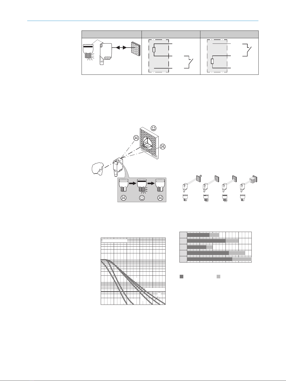
Table 6: Test
Test → M Test → L+
+ (L+)
Test
– (M)
+ (L+)
Test
– (M)
ADDITIONAL FUNCTIONS 6
8020348.14CS | SICK
Subject to change without notice 7

Test → M Test → L+
+ (L+)
Test
– (M)
+ (L+)
Test
– (M)
7 Commissioning
1Alignment
Align the sensor with a suitable reflector. Select the position so that the red emitted light
beam hits the center of the reflector. The sensor must have a clear view of the reflector,
with no object in the path of the beam [see figure 1]. You must ensure that the optical
openings of the sensor and reflector are completely clear.
Figure 1: Alignment 1 Figure 2: Alignment 2
2Sensing range
Adjust the distance between the sensor and the reflector according to the corresponding
diagram [see figure 3] (x = sensing range, y = operating reserve).
0
1,000
100
10
1
2
(6.56)
4
(13.12)
10
(32.81)
8
(26.25)
6
(19.69)
Function reserve
Distance in m (feet)
4
2
1
3
5
Sensing range
WLA16P-xxxxx1xx
Figure 3: Characteristic line 1: Standard
reflector
1Reflector PL22
2Reflector P250, PL30A
3Reflector PL20A
4Reflector PL40A
Sensing range Sensing range typ. max.
1
2
3
4
5
0
3.5 50
6 80
3 4
0
6.5 9
0
7 10
0
8
(26.25)
Distance in m (feet)
2
(6.56)
6
(19.69)
10
(32.81)
4
(13.12)
Figure 4: Bar graph 1: Standard reflector
1Reflector PL22
2Reflector P250, PL30A
3Reflector PL20A
4Reflector PL40A
5Reflector PL80A, C110A
7 COMMISSIONING
88020348.14CS | SICK
Subject to change without notice

5Reflector PL80A, C110A
0
100
10
1
3
2
1
1,000
2
(6.56)
4
(13.12)
10
(32.81)
8
(26.25)
6
(19.69)
Function reserve
Distance in m (feet)
Sensing range
WLA16P-xxxxx1xx
Figure 5: Characteristic line 2: Reflective
tape
1Reflective tape REF-DG
2Reflective tape REF-IRF-56
3Reflective tape REF-AC1000
1
2
30
0
1 2
0
1.8 3
0
4.5 6
0
Sensing range Sensing range typ. max.
8
(26.25)
Distance in m (feet)
2
(6.56)
6
(19.69)
10
(32.81)
4
(13.12)
Figure 6: Bar graph 2: Reflective tape
1Reflective tape REF-DG (50 x
50 mm)
2Reflective tape REF-IRF-56 (50 x
50 mm)
3Reflective tape REF-AC1000 (50 x
50 mm)
1,000
100
10
1
4
3
1
2
02
(6.56)
4
(13.12)
10
(32.81)
8
(26.25)
6
(19.69)
Function reserve
Distance in m (feet)
Sensing range
WLA16P-xxxxx1xx
Figure 7: Characteristic line 3: Fine triple
reflectors
1Reflector PL10FH-1
2Reflector PL10F
3Reflector PL20F
4Reflector P250F
1
2
3
40
0
3 4
0
2.5 3
0
3.8 5
0
6 8
0
Sensing range Sensing range typ. max.
8
(26.25)
Distance in m (feet)
2
(6.56)
6
(19.69)
10
(32.81)
4
(13.12)
Figure 8: Bar graph 3: Fine triple reflectors
1Reflector PL10FH-1
2Reflector PL10F
3Reflector PL20F
4Reflector P250F
COMMISSIONING 7
8020348.14CS | SICK
Subject to change without notice 9

0
1,000
100
10
1
2
(6.56)
4
(13.12)
10
(32.81)
8
(26.25)
6
(19.69)
Function reserve
Distance in m (feet)
5
4
3
21
Sensing range
WLA16P-xxxxx1xx
Figure 9: Characteristic line 4: Chemical-
resistant reflector
1Reflector PL10F CHEM
2Reflector PL20 CHEM
3Reflector P250 CHEM
4Reflector P250H
5Reflector PL40A Antifog
Sensing range Sensing range typ. max.
1
2
3
4
50
0 8
(26.25)
1.4 2
0
2.4 3.5
0
3.5 5
0
4 6
0
6 8
0
Distance in m (feet)
2
(6.56)
6
(19.69)
10
(32.81)
4
(13.12)
Figure 10: Bar graph 4: Chemical-resistant
reflector
1Reflector PL10F CHEM
2Reflector PL20 CHEM
3Reflector P250 CHEM
4Reflector P250H
5Reflector PL40A Antifog
3Time function setting
1
0
T1
T2
M
T4
T3
t
t
t t t t
t t t t
t t t tt
t t
Input signal
0
T1
T2
T3
T4
M = Manual (specific setting via IO-Link)
1 ms 30.000 ms
2
4Setting light/dark switching
7 COMMISSIONING
10 8020348.14CS | SICK
Subject to change without notice

1
L
D
M
Llight switching
DDark switching
Mmanual (specific setting via IO-Link)
8 Process data structure
Process data structure (Version 1.1)
A00 A70 A71 A72 A73 A75
IO-Link V1.1
Process
data
2 bytes 4 bytes
Byte 0: bits 15... 8
Byte 1: bits 7... 0
Byte 0: bits 31...
24
Byte 1: bits 13...
16
Byte 2: bits 15...
8
Byte 3: bits 7... 0
Bit 0 / Data
type
QL1 / Boolean
Bit 1 / Data
type
QL2 / Boolean Qint.1 /
Boolean
QL2 /
Boolean
Qint.1 / Boolean
Bit... /
Descrip‐
tion / Data
type
2 ...15 /
[empty]
2 ...15 /
[time mea‐
surement
value] /
UInt 14
2 … 15 /
[counter
value] /
UInt 14
2 … 15 /
[length /
speed
measure‐
ment] /
SInt14
2 / Qint.
1 /
Boolean
2 … 7 / [empty]
Bit... /
Descrip‐
tion / Data
type
3 … 15 /
[time mea‐
surement
value] /
UInt13
8 … 31 / [carrier
load] / UInt 24
9 Troubleshooting
The Troubleshooting table indicates measures to be taken if the sensor stops working.
LED indicator/fault pattern Cause Measures
Green LED flashes IO-Link communication None
Switching outputs do not
behave in accordance with
table 4 - table 5
1. IO-Link communication
2. Change of the configuration
3. Short-circuit
1. None
2. Adjustment of the configura‐
tion
PROCESS DATA STRUCTURE 8
8020348.14CS | SICK
Subject to change without notice 11

LED indicator/fault pattern Cause Measures
3. Check electrical connections
Not all blue LEDs light up. a) Insufficient alignment
b) Contamination of the
optical surfaces
c) Particles in the light
beam
d) Distance between sen‐
sor and reflector is too
large
e) Reflector is not suitable
a) Check alignment
b) Cleaning of the optical
surfaces (sensor and
reflector).
c) Avoid contamination in
the air as far as possible
d) Check sensing range
e) SICK reflector is recom‐
mended
Yellow LED flashes Distance between sensor and
reflector is too large / light
beam is not completely
aligned to the reflector /
reflector is not suitable / Front
screen and/or reflector is con‐
taminated.
Check sensing range / check
alignment / SICK reflector is
recommended / Cleaning of
the optical surfaces (sensor
and reflector).
10 Disassembly and disposal
The sensor must be disposed of according to the applicable country-specific regula‐
tions. Efforts should be made during the disposal process to recycle the constituent
materials (particularly precious metals).
NOTE
Disposal of batteries, electric and electronic devices
•According to international directives, batteries, accumulators and electrical or
electronic devices must not be disposed of in general waste.
•The owner is obliged by law to return this devices at the end of their life to the
respective public collection points.
•
This symbol on the product, its package or in this document, indicates
that a product is subject to these regulations.
11 Maintenance
SICK sensors are maintenance-free.
We recommend doing the following regularly:
•Clean the external lens surfaces
•Check the screw connections and plug-in connections
No modifications may be made to devices.
Subject to change without notice. Specified product properties and technical data are
not written guarantees.
12 Technical data
WLA16P
Sensing range (with reflector PL80A) 0 m ... 7 m
Light spot diameter/distance Ø 80 mm (5 m)
10 DISASSEMBLY AND DISPOSAL
12 8020348.14CS | SICK
Subject to change without notice

WLA16P
Supply voltage UBDC 10 ... 30 V
Ripple ≤ 5 VSS
Current consumption ≤ 30 mA1)
< 50 mA2)
Output current Imax. ≤ 100 mA
Max. response time ≤ 500 μs3)
Switching frequency 1000 Hz4)
Enclosure rating5) see table 1:
x4, xH, x5, xI: IP66, IP67, IP696)
x9, xB: IP65
Protection class III
Circuit protection A, B, C, D7)
Ambient operating temperature –40 °C ... +60 °C8)
1) 16 VDC to 30 VDC, without load
2) 10 VDC to 16 VDC, without load
3) Signal transit time with resistive load in switching mode. Deviating values possible in COM2 mode.
4) With a light/dark ratio of 1:1 in switching mode. Deviating values possible in IO-Link mode.
5) Pursuant to EN 60529
6) Replaces IP69 K pursuant to ISO 20653: 2013-03
7) A = UB-connections reverse polarity protected
B = inputs and output reverse-polarity protected
C = Interference suppression
D = outputs overcurrent and short-circuit protected
8) Do not bend cables below 0°C.
12.1 Dimensional drawings
20
Ø 12,9
Ø 4,1
39,9
55,4
45,5 5
42
29,9
6
3
6,5
15
27,8
7,7
7,8
7,2
35,5
4,1
8,3
55,7
3
2
34,5
1
4
65
Figure 11: Dimensional drawing 1, cable
1Center of optical axis
2Fixing hole, Ø 4.1 mm
3Connection
4LED indicator green: Supply voltage
active
5LED indicator yellow: Status of
received light beam
6BluePilot blue: Alignment aid
20
M12
18
Ø 4,1
39,9
55,4
55,7
45,5 5
7
42
29,9
52,9
6
17,5
3
6,5
15
28
7,5
35,5
4,1
3
2
34,5
1
4
65
Figure 12: Dimensional drawing 2, male
connector
TECHNICAL DATA 12
8020348.14CS | SICK
Subject to change without notice 13

Beschriebenes Produkt
WLA16
Hersteller
SICK AG
Erwin-Sick-Str. 1
79183 Waldkirch
Deutschland
Rechtliche Hinweise
Dieses Werk ist urheberrechtlich geschützt. Die dadurch begründeten Rechte bleiben
bei der Firma SICK AG. Die Vervielfältigung des Werks oder von Teilen dieses Werks ist
nur in den Grenzen der gesetzlichen Bestimmungen des Urheberrechtsgesetzes zuläs‐
sig. Jede Änderung, Kürzung oder Übersetzung des Werks ohne ausdrückliche schriftli‐
che Zustimmung der Firma SICK AG ist untersagt.
Die in diesem Dokument genannten Marken sind Eigentum ihrer jeweiligen Inhaber.
© SICK AG. Alle Rechte vorbehalten.
Originaldokument
Dieses Dokument ist ein Originaldokument der SICK AG.
2006/42/EC
NO
SAFETY
8020348.14CS | SICK
Subject to change without notice 15

Inhalt
13 Zu Ihrer Sicherheit............................................................................. 17
13.1 Allgemeine Sicherheitshinweise.............................................................. 17
13.2 Hinweise zur UL Zulassung...................................................................... 17
14 Bestimmungsgemäße Verwendung............................................... 17
15 Bedien- und Anzeigeelemente........................................................ 17
16 Montage.............................................................................................. 18
17 Elektrische Installation..................................................................... 18
18 Zusatzfunktionen.............................................................................. 20
19 Inbetriebnahme................................................................................. 21
20 Prozessdatenstruktur........................................................................ 24
21 Störungsbehebung............................................................................ 24
22 Demontage und Entsorgung............................................................ 25
23 Wartung.............................................................................................. 25
24 Technische Daten.............................................................................. 26
24.1 Maßzeichnungen...................................................................................... 26
INHALT
16 8020348.14CS | SICK
Subject to change without notice

13 Zu Ihrer Sicherheit
13.1 Allgemeine Sicherheitshinweise
■Lesen Sie vor der Inbetriebnahme des Geräts die Betriebsanleitung.
■
Der Anschluss, die Montage und die Konfiguration des Geräts dürfen nur
von geschultem Fachpersonal vorgenommen werden.
■
2006/42/EC
NO
SAFETY
Bei diesem Gerät handelt es sich um kein sicherheitsgerichtetes Bauteil im
Sinne der EU-Maschinenrichtlinie.
■
Bei der Inbetriebnahme ist das Gerät ausreichend vor Feuchtigkeit und Ver‐
schmutzung zu schützen.
■Die vorliegende Betriebsanleitung enthält Informationen, die während des Lebens‐
zyklus der Lichtschranke benötigt werden.
13.2 Hinweise zur UL Zulassung
The device must be supplied by a Class 2 source of supply.
UL Environmental Rating: Enclosure type 1
14 Bestimmungsgemäße Verwendung
Die WLA16 ist eine optoelektronische Reflexions-Lichtschranke (im Folgenden Sensor
genannt) und wird zum optischen, berührungslosen Erfassen von Sachen, Tieren und
Personen eingesetzt. Zur Funktion wird ein Reflektor benötigt. Bei jeder anderen Ver‐
wendung und bei Veränderungen am Produkt verfällt jeglicher Gewährleistungsan‐
spruch gegenüber der SICK AG.
15 Bedien- und Anzeigeelemente
WLA16x-xxxxxx00 WLA16x-xxxxxx01 WLA16x-xxxxxx02
1
2
3
1
23
5
1
23
4
1BluePilot blau: Ausrichthilfe
2Anzeige-LED gelb: Status Lichtempfang
3Anzeige-LED grün: Betriebsspannung aktiv
4Drück-Dreh-Element: Einstellung der Zeitfunktionen
5Teach-Taste: Einstellung hell-/dunkelschaltend
ZU IHRER SICHERHEIT 13
8020348.14CS | SICK
Subject to change without notice 17

16 Montage
Sensor und Reflektor an geeignete Befestigungswinkel montieren (siehe SICK-Zubehör-
Programm). Sensor und Reflektor zueinander ausrichten.
Maximal zulässiges Anzugsdrehmoment des Sensors von < 1,3 Nm beachten.
17 Elektrische Installation
Anschluss der Sensoren muss spannungsfrei erfolgen. Je nach Anschlussart sind die
folgenden Informationen zu beachten:
– Steckeranschluss: Pinbelegung beachten
– Leitung: Adernfarbe
Erst nach Anschluss aller elektrischen Verbindungen die Spannungsversorgung anlegen
bzw. einschalten.
Erläuterungen zum Anschlussschema (Tabelle 7 - Tabelle 6)
Alarm = Alarmausgang
Health = Alarmausgang
MF (Pin-2-Konfiguration) = Externer Eingang, Teach-in, Schaltsignal
QL1/C = Schaltausgang, IO-Link Kommunikation
Test = Testeingang
UB: 10 ... 30 V DC
Tabelle 7: Anschlüsse
Wxx16x- x4 xH x5 xI
1 = BN
2 = WH
3 = BU
4 = BK
5= GY
12
4 3
0.14 mm2
AWG26
12
5
4 3
0.14 mm2
AWG26
Wxx16x- x9 xB
1 = BN
2 = BU
3 = not connected
4 = BK
5= WH
6 = GY
7 = not connected
3 4
1
2 5
6
IN = 4 A
3
7
2
16
5
4
IN = 6 A
16 MONTAGE
18 8020348.14CS | SICK
Subject to change without notice

Tabelle 8: DC
WLA16
x-
xx16XxxxA00 xx16Xx
xxA01-
A99
xx161 xx162 xx163 xx165 xx168 xx16A xx16L xx16N xx16x
1 = BN + (L+)
2 = WH MF
3 = BU - (M)
4 = BK QL1/C
Default:
MF
QQAlarm Alarm Test →
L+
no func‐
tion
Test →
L+
no func‐
tion
www.sic
k.com
80227
09
Default:
QL1/C
QQQQQ Q Q Q www.sic
k.com
80227
09
Tabelle 9: DC
WLA16x- xxXXXxxxZZZ
xx111 xx112 xx114 xx116 xx421 xx422 xx721 xx722
BN + (L+)
WH QQHealth Health Q QQQ
BU - (M)
BK QQQQQQQQ
GR - - - - Test → L
+
Test → L
+
Test →
M
Test →
M
Tabelle 10: Push/Pull
Q
push-pull
(≤ 100 mA)
+ (L+)
Q
‒ (M)
+ (L+)
Q
‒ (M)
Q
push-pull
(≤ 100 mA)
+ (L+)
Q
‒ (M)
+ (L+)
Q
‒ (M)
ELEKTRISCHE INSTALLATION 17
8020348.14CS | SICK
Subject to change without notice 19
Other manuals for Bluetooth WLA16
1
Table of contents
Languages:
Other SICK Accessories manuals

SICK
SICK CSM User manual

SICK
SICK T-EASIC FTS User manual

SICK
SICK RMS3 Series User manual

SICK
SICK TriSpectorP1000 User manual

SICK
SICK LMS4000 User manual

SICK
SICK SIM1012 User manual

SICK
SICK WS24-2 Series User manual

SICK
SICK ZLD18 User manual

SICK
SICK WLG16 Bluetooth User manual

SICK
SICK RMS3 Series User manual

SICK
SICK PowerProx WTT12L User manual

SICK
SICK deTem4 Core IP69K User manual

SICK
SICK AS30 Prime Edge User manual

SICK
SICK DC12-24V User manual

SICK
SICK SureSense HSE18 Series User manual

SICK
SICK W4F User manual

SICK
SICK TiM361S User manual

SICK
SICK G6 Inox User manual

SICK
SICK RFU61 Series User manual

SICK
SICK GTB6L-P1 Series User manual