SICK JEF300 Manual

TECHNICAL INFORMATION
JEF300/JEF500
Laser Measurement Sensors
Mounting, electrical installation and
data output formats

Technical Information
JEF300/500 laser measurement sensors
2©SICK AG · Germany · All rights reserved · Subject to change without notice 8014672/0000/2012-05-08
Copyright
Copyright 2012
SICK AG Waldkirch
Identification & Measuring, Reute Plant
Nimburger Strasse 11
79276 Reute
Germany
Trademark
Windows 2000TM, XPTM, VistaTM, Windows 7TM are registered trademarks or trademarks of
the Microsoft Corporation in the USA and other countries.
AdobeReaderis a registered trademark of Adobe Systems Incorporated.
Download via Internet: http://get.adobe.com/reader/

Technical Information Chapter 1
JEF300/500
About this document
8014672/0000/2012-05-08 ©SICK AG · Germany · All rights reserved · Subject to change without notice 3
1About this document
1.1 Information overview
Additional information on the mounting and electrical installation as well on the data out-
put formats of measured values (JEF500 and JEF300) and of the Level Control result
(JEF300) is summarized in this document. It is intended for suitably qualified installation
and commissioning personnel, and can be applied to configuration, commissioning and fur-
ther data processing.
Notes on commissioning, configuration with SOPAS-ET and maintenance is included in the
operating instructions for JEF300 respectively for JEF500.
Information on the JEF300/500 can also be referred to in the Internet on the product page
for the JEF300/500 under www.mysick.com/en/jef300 respectively .../jef500:
Technical data in the online data sheet (PDF)
Dimensional drawing and 3D CAD dimension models in various electronic formats
Operating range diagrams
EC Declaration of Conformity (PDF)
Overview and description of the command strings
SOPAS-ET configuration software
JEF300/500 product information with an overview of the accessories (PDF)
JEF300 operating instructions and JEF500 operating instructions (PDF)
This JEF300/500 technical information (PDF)
Support is also available from your sales partner to be found under
www.sick.com/worldwide.
Symbols used
Some information in this document is highlighted as follows to facilitate quick access to this
information.
NOTICE
Note!
A notice refers to a potential risk of damage or loss of function of the JEF300/500 or the
devices connected up to it.
WARNING
Warning!
A warning refers to specific or potential dangers to the physical safety of the user. It is there
to protect the user against accidents.
The safety mark next to the warning, on the left, refers to the type of accident risk, e.g. elec-
tricity-related. The ascending warning levels (CAUTION, WARNING, DANGER) refer to the se-
verity of the possible danger.
Always read the warnings carefully and make sure you comply with them.
Important This important note is there to advise you on special aspects.

Chapter 1Technical Information
JEF300/500 laser measurement sensors
4©SICK AG · Germany · All rights reserved · Subject to change without notice 8014672/0000/2012-05-08
About this document
This symbol refers to supplementary technical documentation.
1.2 Safety information
Read the notes on mounting and electrical installation prior to carrying out the work.
Read additionally the operating instructions of the JEF300 respectively JEF500 to fa-
miliarize yourself with the device and its functions.
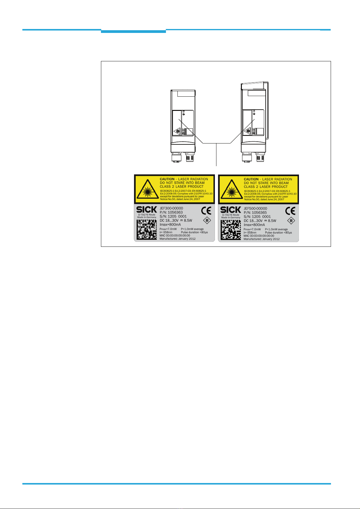
The JEF300/500 corresponds to laser class 2. For more on this, see Section “Laser
warning“, Page 5.
The JEF300/500 is an active sensor. It does not require any illumination for the objects,
any reflectors or position markers.
The JEF300/500 can only safely detect parts of objects, e.g. edges, surrounds or pro-
truding parts, when the area visible for the JEF300/500 is at least three times the an-
gular resolution resulting from the distance to the zero point. If the area is smaller,
distance measurements outside the tolerance of the JEF300/500 may be produced.
Function of the JEF300:
The JEF300 works as a triggered detection sensor in the Level Control application (e.g.
check for complete presence or absence of objects in a matrix). The detection process
can be started and ended via max. two physical switching inputs among other things.
The JEF300 outputs the results after the detection process is complete switching via
max. two physical switching outputs. The results are displayed based on selectable el-
ements from the matrix (matrix complete, row, column or element)
The additional use of a CDB620 connection module with the optional CMC600 param-
eter memory module provides software-controlled expansion by 2 additional switching
inputs and outputs. They are not suitable for time critical applications such as connect-
ing an incremental encoder.
After completing the detection process, the JEF300 also outputs the results as data via
the requesting data interface. After switching on the JEF300, the data is subscribed to
once by command. The results include element-related height values and the status of
the switching threshold evaluation via all rows, columns and elements of the entire ma-
trix.
Function of the JEF500:
As a triggered measurement sensor, the JEF500 outputs the measured values (scan
angle-related radial distance, remission, etc.) via the requesting data interface. After
switching on the JEF500, the data is subscribed to once by command. The data is only
output in realtime via a port of the Ethernet interface.
Only use the device under permitted ambient conditions (e.g. designated region, tem-
perature, ground potential). Where necessary, official and statutory regulations govern-
ing the operation must be complied with.
Opening the screws of the JEF300/500 housing will invalidate any warranty claims
against SICK AG.
Repair work on the JEF300/500 may only be performed by qualified and authorized
service personnel from SICK AG.
The JEF300/500 laser measurement sensors are not devices for protecting persons
as defined by current machine safety standards.

Technical Information Chapter 1
JEF300/500
About this document
8014672/0000/2012-05-08 ©SICK AG · Germany · All rights reserved · Subject to change without notice 5
Laser warning
CAUTION
Laser radiation!
The JEF300/500 uses a red light laser diode and corresponds to laser class 2.
The entire measurement window is a an outlet opening for the visible laser radiation.
The human eye is not at risk when accidentally exposed to the laser radiation for short pe-
riods of time (up to 0.25 s). When intentionally exposed to the laser beam for longer periods
of time, the retina of the eye may be damaged. The emitted radiation is harmless to human
skin.
Caution – incorrect use can lead to the user beeing exposed to dangerous radiation.
Never look directly into the beam path (similar to sunlight)
Never point the laser beam at the eyes of people.
When mounting and aligning the JEF300/500, avoid reflections of the laser beam off
reflective surfaces.
Do not open the closed JEF300/500 housing because this operation does not interrupt
possible activation of the laser diode.
Comply with the latest version of the applicable provisions on laser protection.
Important Maintenance is not necessary to ensure compliance with laser class 2.
Line scanner Line scanner with oscillating mirror
Outlet opening

Chapter 1Technical Information
JEF300/500 laser measurement sensors
6©SICK AG · Germany · All rights reserved · Subject to change without notice 8014672/0000/2012-05-08
About this document
Laser warning/laser specifications labels
The JEF300/500 includes two self-adhesive laser warning labels in German or French for
replacement as required.
Controlling the laser diode
In real detection mode (JEF300) or measurement mode (JEF500), the JEF300/500 turns
the laser diode on and off for moving objects with the trigger signal of the conveyor system
(object in field of view). Triggering occurs via the switching inputs of the JEF300/500 or by
two commands via one of the data interfaces.
A laser timeout that can be adjusted using SOPAS ET can automatically turnoff the laser
diode in this type of object trigger control, e.g. cycle stopped too long (conveyor system
stopped). If the function is activated, the laser timeout is 10 min (default).
In the "Free running" or "Auto cycle" cycle types, the laser diode is turned on continuously or
cyclically and a set laser timeout has no effect.
The "Laser" LED on the JEF300/500 illuminates while the laser diode is on. The JEF300/
500 independently monitors beam generation and automatically shuts down the laser di-
ode in the event of irregularities. In such case, the "Ready" LED illuminates red. The
JEF300/500 no longer sends any detection result (JEF300) or measured values (JEF500).
Line scanner
JEF300 JEF500
Line scanner with
oscillating mirror

Technical Information
JEF300/500
Contents
8014672/0000/2012-05-08 ©SICK AG · Germany · All rights reserved · Subject to change without notice 7
Table of contents
1 About this document.........................................................................................................3
1.1 Information overview .....................................................................................................3
1.2 Safety information..........................................................................................................4
2 Mounting.............................................................................................................................8
2.1 Notes on mounting.........................................................................................................8
2.2 Optional accessories......................................................................................................9
2.3 Mounting the CDB620-001 connection module....................................................... 10
3 Electrical installation ..................................................................................................... 11
3.1 Overview of all interfaces and connection options................................................... 11
3.2 Pin assignments .......................................................................................................... 13
3.3 Pin assignments and lead color assignments of cables .......................................... 14
3.4 Notes on the electrical installation ............................................................................ 17
3.5 Prerequisites for the safe operation of the JEF300/500 in a system .................... 18
3.6 Installation steps......................................................................................................... 21
3.7 Using the CDB620-001 connection module ............................................................. 27
4 Measured value output.................................................................................................. 40
4.1 Telegrams ....................................................................................................................40
4.2 Request of measured values (subscription) ............................................................. 41
4.3 Measured value output format .................................................................................. 43

Chapter 2Technical Information
JEF300/500 laser measurement sensors
8©SICK AG · Germany · All rights reserved · Subject to change without notice 8014672/0000/2012-05-08
Mounting
2Mounting
2.1 Notes on mounting
General:
Use optional mounting kits 1, 2 or 3 depending on the application for a required fine
adjustment in 2 or 3 axe.
See Chapter 2.2 Optional accessories, Page 9.
Mount the JEF300/500, so that:
– The measurement can be taken free of shock and vibration.
– It has a clear view of the object to be measured.
– For the line scanner, the scan line is at a right angle to the direction of transport.
– The line scanner with oscillating mirror is plane-parallel to the level ground.
– It is minimum 400 mm above the highest object.
– The position of the 90° beam (vertically downwards) is centered over the conveyor
system width to minimize measurement shadowing by the radial scanning.
– Its laser beam does not shine on glossy or reflective objects (e.g. stainless steel, win-
dow). This can produce measured value jumps in the measurement results.
– Illumination by ambient light does not exceed 2,000 lx.
– It is not exposed to direct sunlight (window, skylight) or other sources of heat. This
causes the temperature in the device to increase improperly.
The objects can be moved on a conveyor system with a flat transporting surface. Rota-
tion, vibration, swaying and slipping of the objects on the conveyor system and uneven
transporting surfaces can reduce the measurement accuracy and degrade the evalua-
tion of detecting respectively distance measuring.
Line scanner: The conveyor system must have a constant conveyor velocity or an incre-
mental encoder must be installed and connected.
JEF300:
Mount the JEF300 as high as possible within its operating range and with the laser
beam vertically downwards above the guided objects.
JEF500:
The JEF500 can be mounted in any position depending on the purpose. If the measure-
ment is taken from above, mount the JEF500 as high as possible within its operating
range and with the laser beam vertically downwards above the guided objects.

Technical Information Chapter 2
JEF300/500
Mounting
8014672/0000/2012-05-08 ©SICK AG · Germany · All rights reserved · Subject to change without notice 9
2.2 Optional accessories
2.2.1 Installing mounting set 1 (part no. 2042800)
2.2.2 Installing mounting set 2 (part no. 2042801)
51
101.3
2.5
61.5
5.4
27
16
50.65
Ø 5.4
35.5
5.4
45.5
Ø 5.4
Ø 32
Included to fix the JEF300/500 to the bracket:
• 3 x cylinder head screws M5 x 8 mm, with hexagon socket, self-locking
• 3 x spring washer A5
All dimensions in mm
mm
2.5
5.4
16
27
32
35.5
inch
0.09
0.21
0.63
1.06
1.26
1.39
mm
45.5
50.65
51
61.5
101.3
inch
1.79
1.99
2.00
2.42
3.99
5.4
45.5
Ø 5,4
Ø 32
Ø 40
101.3
2.5
61.5
Ø 20
51
61.8
56
50.65
38.3
7 x 45°
M8
Ø 12
Included to fix the JEF300/500 to the bracket:
• 3 x cylinder head screws M5 x 8 mm, with hexagon socket, self-locking
• 3 x spring washer A5 All dimensions in mm
mm
2.5
5.4
12
20
32
38.3
40
inch
0.09
0.21
0.47
0.78
1.26
1.51
1.57
mm
45.5
50.65
51
56
61.5
61.8
101.3
inch
1.79
1.99
2.00
2.20
2.42
2.43
3.99

Chapter 2Technical Information
JEF300/500 laser measurement sensors
10 ©SICK AG · Germany · All rights reserved · Subject to change without notice 8014672/0000/2012-05-08
Mounting
2.2.3 Installing mounting set 3 (part no. 2042799) with shock absorber
2.3 Mounting the CDB620-001 connection module
The mounting location for the connection module (distance to JEF300/500) depends on the
physical design of the serial data interface (configuration/data output) used.
The permissible cable lengths are listed in Section “Wiring serial data interfaces:“, Page 23.
For detailed information on mounting and the electrical installation, see "CDB620 connec-
tion module" operating instructions (part no. 8012119, Ger./Engl. version) supplied in print-
ed form.
Included to fix the JEF300/500 to the bracket:
• 3 x cylinder head screws M5 x 8 mm, with hexagon socket, self-locking
• 3 x spring washer A5
69.5
101.3
2.5
80
6
Ø 5.4
Ø 32
64
43
5.4
40
Ø 5.4
32
37
5.4
M5 (4x)
All dimensions in mm
mm
2.5
5.4
6
32
37
40
inch
0.09
0.21
0.23
1.26
1.45
1.57
mm
43
64
69.5
80
101.3
inch
1.69
2.52
2.73
3.15
3.99

Technical Information Chapter 3
JEF300/500
Electrical installation
8014672/0000/2012-05-08 ©SICK AG · Germany · All rights reserved · Subject to change without notice 11
3Electrical installation
3.1 Overview of all interfaces and connection options
JEF300/JEF500: Configuration/Diagnosis
JEF300: Detection mode
JEF500: Measurement mode
JEF300/500
e.g. cable no. 2055419 (2 m/6.56 ft)
CDB620 connection module (optional)
SerialSerial
e.g. cable no. 6034414 (2 m/6.56 ft)
Configuration
Diagnosis
SOPAS ETSOPAS ET
EthernetEthernet
SerialSerial
e.g no. 1042256
...
...
PC
e.g. cable no. 2014054 (2 m/6.56 ft)
“Serial RS-232” (AUX 1) for configuration, alternative to Ethernet
DC 18 ... 30 V
Note:
Configuration/diagnosis of the JEF300/
500 can be done via each of the 4 data
interfaces (AUX 1, AUX 2, HOST 1, HOST2).
Here the Aux port of the Ethernet interface
and alternatively the serial Aux interface
are shown.
AUX 1, HOST 1 AUX 2
“Power/Serial Data/
I/O”
connection
“Ethernet”
connection
4-pin
M12 socket
17-pin M12 plug
Input 2
(e.g. no function)
External input 1
(e.g. start of external object trigger)
External input 2
(e.g. stop of external object trigger)
Input 1
(e.g. incremental encoder)
Output 1
(e.g. column 1, value above switching level 1)
Output 2
(e.g. column 2, value above switching level 2)
External output 1
(e.g. column 3, value above switching level 3)
External output 2
(e.g. column 4, value above switching level 4)
JEF300
e.g. cable no. 2055419 (2 m/6.56 ft)
SerialSerial
“Power/Serial Data/I/O”
(AUX 1, HOST 1)
“Ethernet”
(HOST 2, result)
e.g. no. 1042256
...
...
DC 18 ... 30 V
CMC600
Inputs/Outputs = digital CMC600 Parameter Memory Module required
432
1
Columns (front view)
Transport movement in direction to the viewer
If required,
result data output
on request
Note:
The JEF300 outputs the result via the data interface on which the result has been requested. Here the Host port of the Ethernet
interface is shown. For high data volume a port of the Ethernet interface is recommended.
CDB620 connection module (optional)
Input 2
(e.g. incremental encoder)
Input 1
(e.g. external measuring trigger)
JEF500
e.g. cable no. 2055419 (2 m/6.56 ft)
CDB620 connection module (optional)
e.g. cable no. 6034414 (2 m/6.56 ft)
EthernetEthernet
SerialSerial
e.g. no. 1042256
...
...
12
DC 18 ... 30 V
GND
HOST
Further data
processing
DC 18 ... 30 V
Note:
The JEF500 outputs the data via the data interface on
which the measuring values have been requested.
For high data volume output a port of the Ethernet
interface is recommended.
Measured valuesHOST 2AUX 1, HOST 1
“Power/Serial Data/
I/O”
connection
“Ethernet”
connection
4-pin
M12 socket
17-pin M12 plug

Chapter 3Technical Information
JEF300/500 laser measurement sensors
12 ©SICK AG · Germany · All rights reserved · Subject to change without notice 8014672/0000/2012-05-08
Electrical installation
3.1.1 Using the data interfaces
The logical Aux interface of the JEF300/500 can operate the serial data interface and Aux
port of the Ethernet interface in parallel.
In a similar manner, the logical Host interface can operate the serial data interface and the
Host port of the Ethernet interface in parallel.
However, the data released by means of a command string is only output on the interface
on which the request was received. For output in real time, one of the two ports of the Ether-
net interface must be selected. The physical RS-232 and RS-422/485 Host interfaces can-
not be used simultaneously.
Possible interface
Assignable function
HOST 1 AUX 1 HOST 2 AUX 2
serial
RS-232/
422/485
serial
RS-232
Ethernet
10/100 Mbit/s
Ethernet
10/100 Mbit/s
Complete application result output
(JEF300)
Mesasured value output (JEF500)
Heartbeat output (JEF300/500)
Configuration (SOPAS, commands)
= The JEF300/500 only outputs the date via the requesting data interface by subscription
= not recommended
= Access only makes practical sense via one of the interfaces (risk of collision)
JEF300/500
Aux 1
RS-232 Configuration
Software
SOPAS ET
HOST:
Further data
processing
Ethernet
Host 1
PC/HOST
RS-2321)
RS-4221)
RS-4851)
1) Select one of the three options
2) recommended on high data volume
◂ Configuration/data output ▸
Aux 2 ◂ Configuration/data output ▸
◂ Configuration/data output ▸
Host 2 ◂ Configuration/data output2) ▸

Technical Information Chapter 3
JEF300/500
Electrical installation
8014672/0000/2012-05-08 ©SICK AG · Germany · All rights reserved · Subject to change without notice 13
3.2 Pin assignments
“Power/Serial Data/I/0” connection Plug of the connection cable
e.g. no. 2055419 (2 m/6.56 ft)
M12 plug,
A-encoded D-Sub HD
4
3
2
1TD+
TD–
RD+
RD–
“Ethernet” connection
M12 socket,
D-encoded
4
32
18715
614
5
17
4
13
3
2
12
1
11
10
9
16
6110
5
11 15
Reserved
Reserved
TD+ (RS-422/485), HOST
TD– (RS-422/485),
TxD (RS-232), HOST
DC 18 ... 30 V
TxD (RS-232), AUX
RxD (RS-232), AUX
RD+ (RS-422/485), HOST
GND
RD– (RS-422/485),
RxD (RS-232), HOST
Output 1
n.c.
n.c.
Output 2
7
6
Input 2
Input 1
INGND
4
3
2
1
5
8
9
10
11
12
13
14
15
16
17
Reserved
Reserved
TD+ (RS-422/485), HOST
TD– (RS-422/485),
TxD (RS-232), HOST
DC 18 ... 30 V
TxD (RS-232), AUX
RxD (RS-232), AUX
RD+ (RS-422/485), HOST
GND
RD– (RS-422/485),
RxD (RS-232), HOST
Output 1
Output 2
7
6
Input 2
Input 1
INGND
4
3
2
1
5
8
9
10
11
12
13
14
15
Input = digital switching input Output= digital switching output

Chapter 3Technical Information
JEF300/500 laser measurement sensors
14 ©SICK AG · Germany · All rights reserved · Subject to change without notice 8014672/0000/2012-05-08
Electrical installation
3.3 Pin assignments and lead color assignments of cables
3.3.1 JEF300/500 ("Power/SerialData/I/0" connection) to CDB620-001
Cable no. 2049764 (0.9 m/2.95 ft), no. 2055419 (2 m/6.56 ft),
no. 2055420 (3 m/9.84 ft)
3.3.2 JEF300/500 ("Ethernet" connection) to PC
Cable no. 6034414 (2 m/6.56 ft), no. 6034415 (5 m/16.4 ft)
Pin Signal Function Pin
2 DC 18 ... 30 V Supply voltage 1
8 RxD (RS-232), AUX Aux interface (receiver) 2
7 TxD (RS-232), AUX Aux interface (sender) 3
15 Input 2 Switching input 2 4
1GND Ground 5
11 RD+ (RS-422/485), Host Host interface (receiver+) 6
12 RD– (RS-422/485)/RxD (RS-232), Host Host interface (receiver–) 7
5 TD+ (RS-422/485), Host Host interface (sender+) 8
6 TD– (RS-422/485)/TxD (RS-232), Host Host interface (sender–) 9
4 Reserved – 10
3 Reserved – 11
13 Output 1 Switching output 1 12
14 Output 2 Switching output 2 13
10 Input 1 Switching input 1 14
9 INGND Common ground for all inputs 15
16 n.c. – –
17 n.c. – –
Pin Signal Function Pin
1 TD+ (Ethernet) Sender+ 1
3 TD– (Ethernet) Sender– 2
2 RD+ (Ethernet) Receiver+ 3
4 RD– (Ethernet) Receiver– 6
6110
5
11 15
17-pin M12 socket,
A-type encoded
(Front view)
15-pin D Sub
HD plug
(Front view)
32
41
4-pin M12 plug, D-type encoded
(Front view)
8-pin RJ-45 plug
(Front view)

Technical Information Chapter 3
JEF300/500
Electrical installation
8014672/0000/2012-05-08 ©SICK AG · Germany · All rights reserved · Subject to change without notice 15
3.3.3 JEF300/500 ("Ethernet" connection) to Ethernet (M12)
Cable no. 6034420 (2 m/6.56 ft), no. 6034421 (3 m/9.84 ft), 6034422 (5 m/16.4 ft)
3.3.4 JEF300/500 ("Power/SerialData/I/0" connection) to customer specific
connection box (power supply)
No. 6042772 (3 m/9.84 ft), no. 6042773 (5 m/16.4 ft)
s
Pin Signal Function Pin
1 TD+ (Ethernet) Sender+ 1
3 TD– (Ethernet) Sender– 2
2 RD+ (Ethernet) Receiver+ 3
–– – 4
–– – 5
4 RD– (Ethernet) Receiver– 6
Pin Signal Function Color of lead
1 GND Ground brown
2 DC 18 ... 30 V Supply voltage blue
3 Reserved – white
4 Reserved – green
5 TD+ (RS-422/485), Host Host interface (receiver+) pink
6 TD– (RS-422/485)/TxD (RS-232), Host Host interface (receiver–) yellow
7 TxD (RS-232), Aux Aux interface (sender) black
8 RxD (RS-232), Aux Aux interface (receiver) gray
9 INGND Common ground for all inputs red
10 Input 1 Switching input 1 purple
11 RD+ (RS-422/485), Host Host interface (receiver+) gray-pink
12 RD– (RS-422/485)/RxD (RS-232), Host Host interface (receiver–) red-blue
13 Output 1 Switching output 1 white-green
14 Output 2 Switching output 2 brown-green
15 Input 2 Switching input 2 white-yellow
16 n.c. – yellow-brown
17 n.c. – white-gray
32
41
32
41
4-pin M12 plug,
D-type encoded
(Front View)
4-pin M12 plug,
D-type encoded
(Front View)
17-pin M12 socket, A-type encoded
(Front view)
...

Chapter 3Technical Information
JEF300/500 laser measurement sensors
16 ©SICK AG · Germany · All rights reserved · Subject to change without notice 8014672/0000/2012-05-08
Electrical installation
3.3.5 CDB620-001 connection module to PC (serial data: Host interface)
No. 2020319 (3 m/9.84 ft)
Pin Signal Function Color of lead CDB620-001 terminal
1– – – –
2 RxD (RS-232) Host interface (receiver) brown 43 (TxD Host)
3 TxD (RS-232) Host interface (sender) blue 44 (RxD Host)
4– – – –
5 GND Ground black 42 (GND)
6– – – –
7– – – –
8– – – –
9– – – –
9-pin D Sub socket
(Front view)
51
96

Technical Information Chapter 3
JEF300/500
Electrical installation
8014672/0000/2012-05-08 ©SICK AG · Germany · All rights reserved · Subject to change without notice 17
3.4 Notes on the electrical installation
Electrical connections between the JEF300/500 and other devices may only be con-
nected or disconnected when the system is not live, otherwise the devices may be dam-
aged.
Turn the swivel connector unit with the electrical connections max. 180° from end po-
sition to end position.
The electrical circuits connected to the JEF300/500 (e.g. switching inputs with external
powered sensors) must be implemented as SELV or PELV electrical circuits.
(SELV = Safety-Extra-Low-Voltage, PELV = Protective-Extra-Low-Voltage).
Do not switch on the supply voltage for the JEF300/500/the CDB620-001 connection
module until the connection work has been completed and the wiring work has been
tested thoroughly.
Prerequisites for enclosure rating IP 65
During normal operation, the cover for the Micro SD card slot (black rubber cover) must
be flush mounted on the housing.
Protect the JEF300/500 from moisture and dust when the cover is temporarily open.
If the Ethernet interface is not used, fit the electrical connection (4-pin M12 socket)
with the yellow protective plug as in delivery state.
The same also applies for the EMC requirements (ESD) according to CE.
Cable lengths for data interfaces
The possible length of cable between JEF300/500 and the host computer depends on the
selected physical design of the host interface and the set data transmission rate. For the
serial interfaces, see Section “Wiring serial data interfaces:“, Page 23.

Chapter 3Technical Information
JEF300/500 laser measurement sensors
18 ©SICK AG · Germany · All rights reserved · Subject to change without notice 8014672/0000/2012-05-08
Electrical installation
3.5 Prerequisites for the safe operation of the JEF300/500 in
asystem
The JEF300/500 is designed and tested for electrical safety according to EN 60950-1
(2006-04)/A11 (2009-03). It is connected to the peripheral devices (power supply, object
trigger sensor(s), PLC, Host etc.) via shielded cables. The cable shield, for example, for the
data cable rests against the metal housing of the JEF300/500. The device can either be
grounded through the cable shield or through the CDB620 connection module.
If the peripheral devices have metal housings and if the cable shields also lie on their hous-
ings, it is assumed that all devices involved in the installation have the same ground poten-
tial.
This is achieved for instance by complying with the following conditions:
Mounting the devices on conductive metal surfaces
Correctly grounding the devices/metal surfaces in the system
If necessary, low-impedance and current carrying equipotential bonding between areas
with different ground potentials.
If these conditions are not met, e.g. on devices in a widely distributed system over several
buildings, potential equalization currents may, due to different ground potentials, flow along
the cable shields between the devices, which can lead to hazards.
DANGER
Risk of injury/risk of damage via electrical current!
Potential equalization currents between the JEF300/500 and other grounded devices in
the system can have the following effects:
Dangerous voltages on the metal housing of the JEF300/500, for instance
Incorrect function or irreparable damage to the devices
Damage/irreparable damage of the cable shield due to heating and cable fires
Where local conditions are unfavorable and thus do not meet conditions for a safe
earthing method (same ground potential at all grounding points), take measures in
accordance with the following formats.
JEF300/500
closed current loop
with equalizing currents
via cable shield
grounding point 2
grounding point 1
grounding potential difference
PLC Object trigger
sensor
I
U
CDB620-
001
= metal housing = plastic housing
= shielded electrical cable

Technical Information Chapter 3
JEF300/500
Electrical installation
8014672/0000/2012-05-08 ©SICK AG · Germany · All rights reserved · Subject to change without notice 19
Remedial measures
The most common solution to prevent potential equalization currents on cable shields is to
ensure low-impedance and current carrying equipotential bonding. If this is not possible, the
following solution approaches serve as a suggestion.
Important We expressly advise against opening up the cable shields. Doing this means that the EMC
limit values can no longer be complied with and that the safe operation of the device data
interfaces can no longer be guaranteed.
a) Measures for widely distributed system installations
On widely distributed system installations with correspondingly large potential differences,
we recommend setting up local islands and connecting them using commercially available
electro-optical signal isolators. This measure achieves a high degree of resistance to elec-
tromagnetic interference while at the same time complying with all the requirements of
EN 60950-1.
The ground loop is isolated by using the electro-optical signal isolator between the islands.
Within the islands, a stable equipotential bonding prevents equalizing currents at the cable
shields.
grounding point 1
Electro-
optical
signal
isolator
Electro-
optical
signal
isolator
PLC
Object
trigger
sensor
grounding point 2
JEF300/500
shielded electrial cablemetal housing fiber optic cable

Chapter 3Technical Information
JEF300/500 laser measurement sensors
20 ©SICK AG · Germany · All rights reserved · Subject to change without notice 8014672/0000/2012-05-08
Electrical installation
b) Measures for small system installations
For smaller installations with only slight potential differences, insulated installation of the
JEF300/500 and of peripheral devices may be a sufficient solution.
Even in the event of large differences in the ground potential, ground loops are effectively
prevented, meaning that equalizing currents can no longer flow via the cable shields and
metal housing.
Important The power supply for the JEF300/500 and the connected peripheral devices must also
guarantee the required level of insulation.
Under certain circumstances, a tangible potential can develop between the insulated metal
housings and the local ground potential.
Special national regulations for Sweden and Norway
Varning och atjarder
Utrustning som ar kopplad till skyddsjord via jordat vagguttag och/eller via annan utrustning
och samtidigt ar kopplad till kabel-TV nat kan i vissa fall medfora risk for brand.
For att undvika detta skall vid anslutning av utrustningen till kabel-TV nat galvanisk iso-
lator finnas mellan utrustningen och kabel-TV natet.
Advarsel og tiltaker
Utstyr som er koplet til beskyttelsesjord via nettplugg og/eller via annet jordtilkoplet utstyr
- og er tilkoplet et kabel - TV nett, kan forarsake brannfare.
For a unnga dette skal det ved tilkopling av utstyret til kabel-TV nettet installeres en gal-
vanisk isolator mellom utstyret og kabel-TV nettet.
Corresponding English translation
Devices which are connected to the electrical system PE of the building via a mains connec-
tion or other devices with a connection to the PE, and which are connected to a cable distri-
bution system with coaxial cables, can under certain circumstances cause a risk of fire.
Connections to a cable distribution system must therefore be made such that electrical
insulation is offered below a certain frequency range (galvanic separating link).
electrically
insulatetd
grounding point 2 grounding point 3grounding point 1
grounding potential difference
U
shielded electrial cable
PLC Object trigger
sensor
JEF300/500
This manual suits for next models
1
Table of contents
Other SICK Accessories manuals

SICK
SICK PowerProx WTT12L User manual

SICK
SICK TiM361S User manual

SICK
SICK OD5000-C15 Series User manual

SICK
SICK PowerProx WTT190L-K Series User manual

SICK
SICK LFV 200 User manual

SICK
SICK LBV 321 NAMUR User manual

SICK
SICK MRS6000 User manual

SICK
SICK MPB10 User manual

SICK
SICK RMS1000 User manual

SICK
SICK RSB User manual