LED indicator/fault pattern /
LED indicator/fault pattern
Cause /
Cause
Measures /
Measures
Ensure there is a stable power
supply without interruptions
Green LED does not light up /
Green LED does not light up
Sensor is faulty /
Sensor is faulty
If the power supply is OK,
replace the sensor /
If the power supply is OK,
replace the sensor
Yellow LED flashes /
Yellow LED flashes
Sensor is still ready for opera‐
tion, but the operating condi‐
tions are not ideal /
Sensor is still ready for opera‐
tion, but the operating condi‐
tions are not ideal
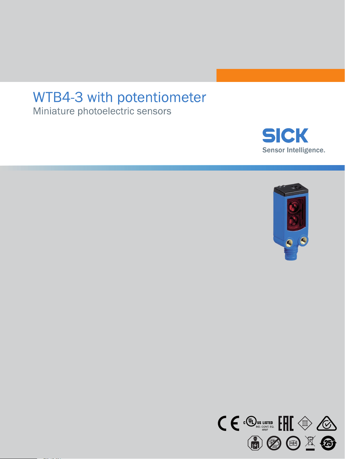
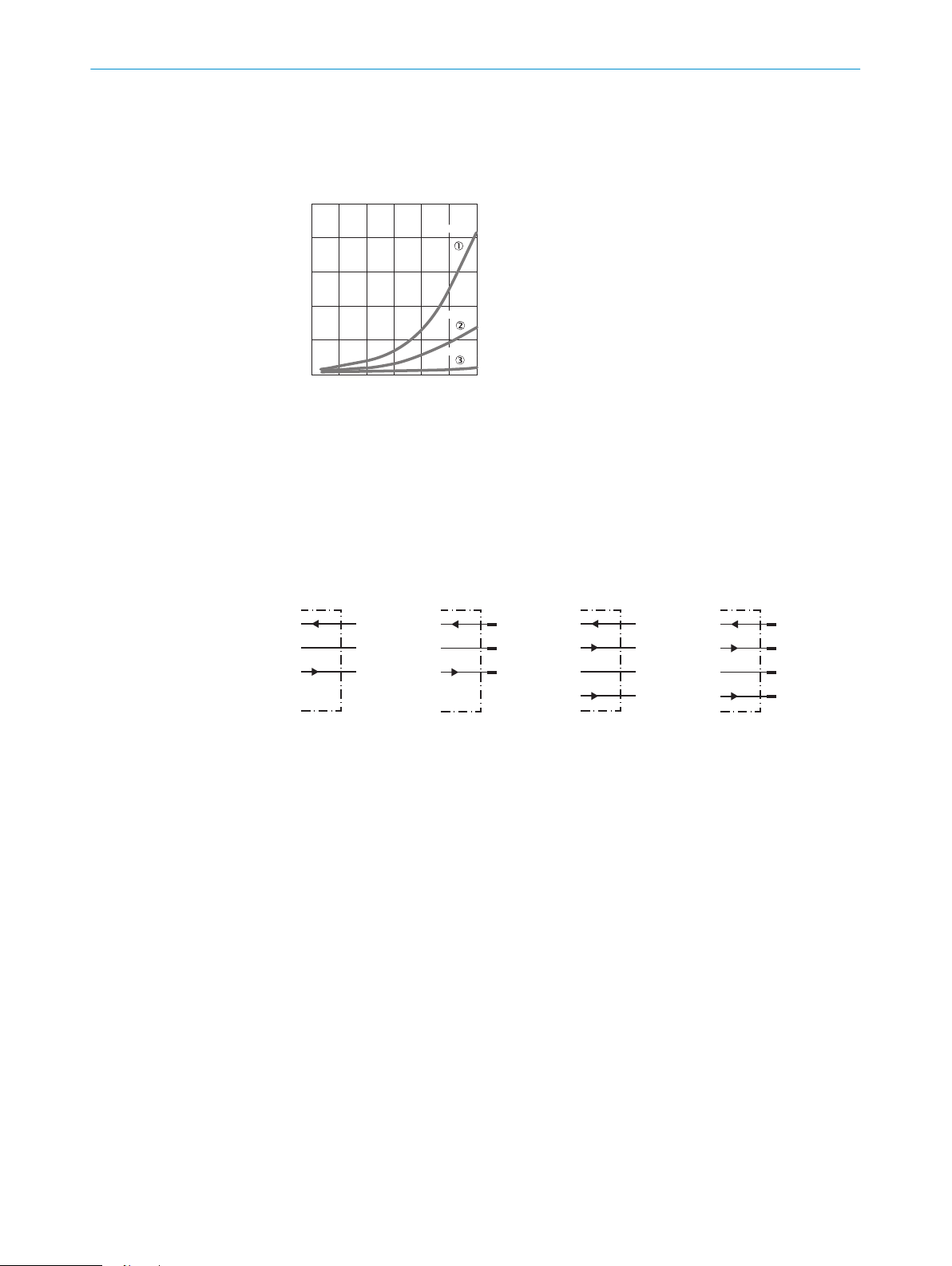
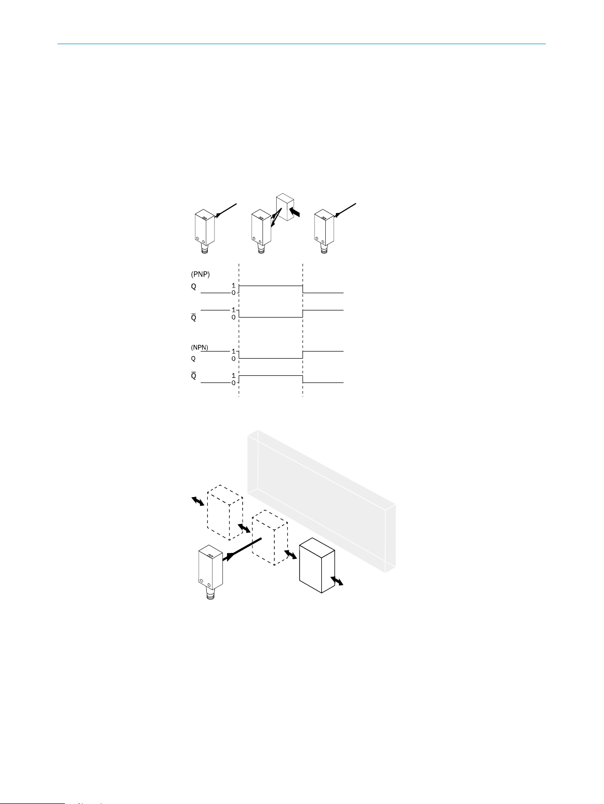
Check the operating condi‐
tions: Fully align the beam of
light (light spot) with the
object. / Clean the optical sur‐
faces . / Readjust the sensitiv‐
ity (potentiometer) / Check
sensing range and adjust if
necessary; see graphic F. /
Check the operating condi‐
tions: Fully align the beam of
light (light spot) with the
object. / Clean the optical sur‐
faces . / Readjust the sensitiv‐
ity (potentiometer) / Check
sensing range and adjust if
necessary; see graphic F.
Yellow LED lights up, no object
in the path of the beam /
Yellow LED lights up, no object
in the path of the beam
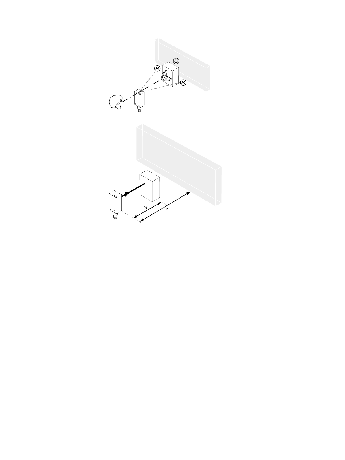
/ Distance between the sen‐
sor and the background is too
short /
/ Distance between the sen‐
sor and the background is too
short
Reduce the sensing range,
see graphic F /
Reduce the sensing range,
see graphic F
Object is in the path of the
beam, yellow LED does not
light up /
Object is in the path of the
beam, yellow LED does not
light up
Distance between the sensor
and the object is too long or
sensing range is set too
short /
Distance between the sensor
and the object is too long or
sensing range is set too short
Increase the sensing range,
see graphic F /
Increase the sensing range,
see graphic F
7 Disassembly and disposal
The sensor must be disposed of according to the applicable country-specific regula‐
tions. Efforts should be made during the disposal process to recycle the constituent
materials (particularly precious metals).
8 Maintenance
SICK sensors are maintenance-free.
We recommend doing the following regularly:
•Clean the external lens surfaces
•Check the screw connections and plug-in connections
No modifications may be made to devices.
Subject to change without notice. Specified product properties and technical data are
not written guarantees.
DISASSEMBLY AND DISPOSAL 7
5
8011449.126R | SICK
Subject to change without notice