SICK Inspector PIM60 User manual

Inspector PIM60 ver 2.0
Vision sensor
REFERENCE MANUAL

WARNING
VSPM-6F2113 (Inspector PIM60), VSPM-6B2113 (Inspector PIM60 Base), VSPM-6F2113S19 (Inspector PIM60
Bead)
The Inspector is equipped with a LED illumination
that must be considered as a lamp system of Risk
Group 1 (low risk) according to IEC 62471:2006
Accessible irradiance at distances > 200 mm:
LB<4 x 10⁴W/(m2sr) within 100 s
LH<106W/(m2sr) within 10 s
WARNING: OPTICAL RADIATION DO NOT STARE INTO BEAM
RISK GROUP 1 (LOW RISK) according to IEC 62471:2006
Visible LED light λ = 400-800 nm
VSPM-6F2313 (Inspector PIM60-LUT), VSPM-6F2313S20 (Inspector PIM60-LUT Bead)
The Inspector is equipped with a LED illumination
that must be considered as a lamp system of Risk
Group 1 (low risk) according to IEC 62471:2006
Accessible irradiance at distances > 200 mm:
ES< 3 x 10⁻³ W/m2within 104s
EUVA < 33 W/m2within 300 s
LR< 7 x 10⁶W/(m2sr) within 10 s
WARNING: OPTICAL RADIATION DO NOT STARE INTO BEAM
RISK GROUP 1 (LOW RISK) according to IEC 62471:2006
UV LED light λ = 385 nm
VSPM-6F2413 (Inspector PIM60-IR), VSPM-6B2413 (Inspector PIM60-IR Base), VSPM-6F2413S18 (Inspector
PIM60-IR Bead)
The Inspector is equipped with an LED illumin-
ation that must be considered as a lamp system
of Risk Group 0 / Free Group (exempt risk) ac-
cording to IEC 62471:2006
Accessible irradiance at distances > 200 mm:
EIR < 100 W/m2within 103s
LIR < 1.2 x 10⁶W/(m2sr) within 103s
NOTICE: IR EMITTED FROM THIS PRODUCT
RISK GROUP 0 (EXEMPT RISK) according to IEC 62471:2006
IR LED light λ = 850 nm
DISCLAIMER
SICK uses standard IP technology for its products, e.g. IO Link, industrial PCs. The focus here is on providing avail-
ability of products and services. SICK always assumes that the integrity and confidentiality of data and rights involved
in the use of the above-mentioned products are ensured by customers themselves. In all cases, the appropriate
security measures, e.g. network separation, firewalls, antivirus protection, patch management, etc., are always im-
plemented by customers themselves, according to the situation.
©SICK AG 2018-09-05
All rights reserved
8015726/ZPP7/2018-09
Subject to change without notice

Table of Contents
Introduction 5
1Introduction .......................................................................................... 6
1.1 Interfaces overview .................................................................... 6
1.2 Intended readers ....................................................................... 6
Interfaces 7
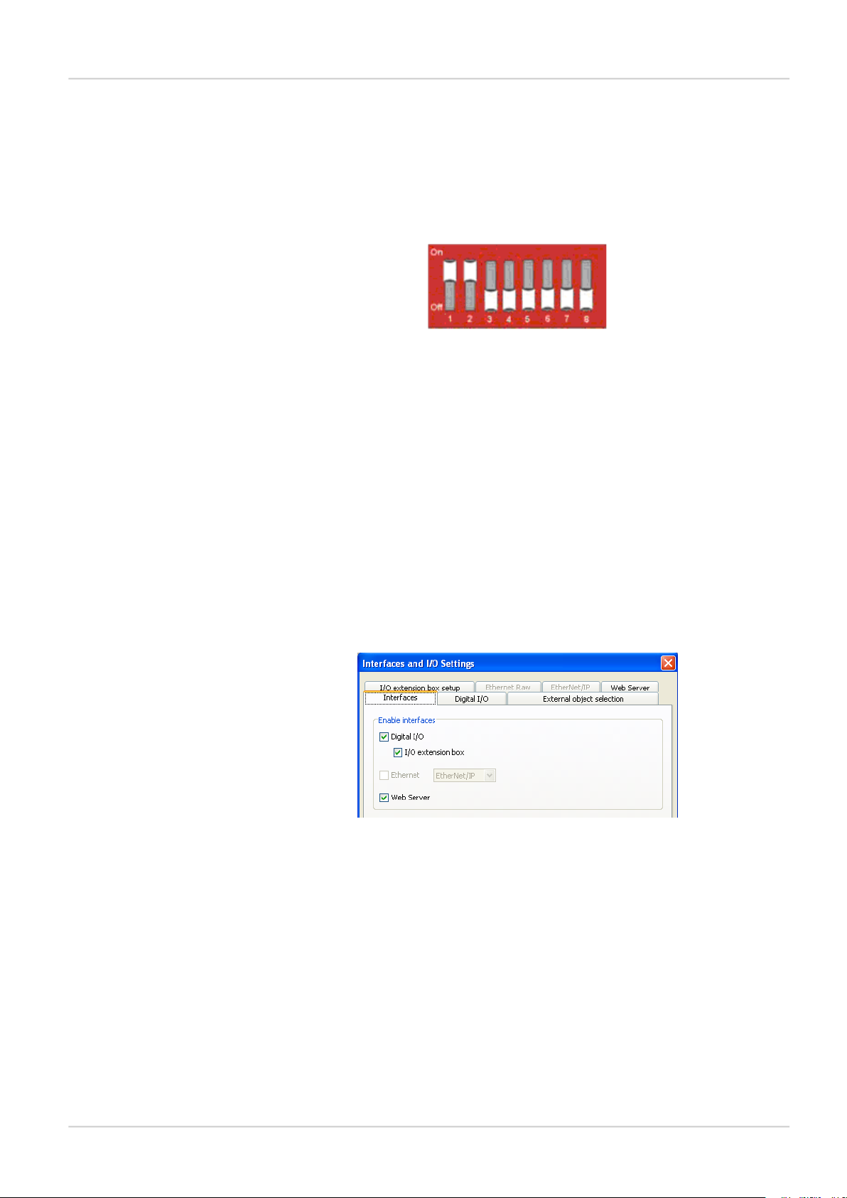
2I/O extension box .................................................................................. 8
2.1 Physical network connection ........................................................ 8
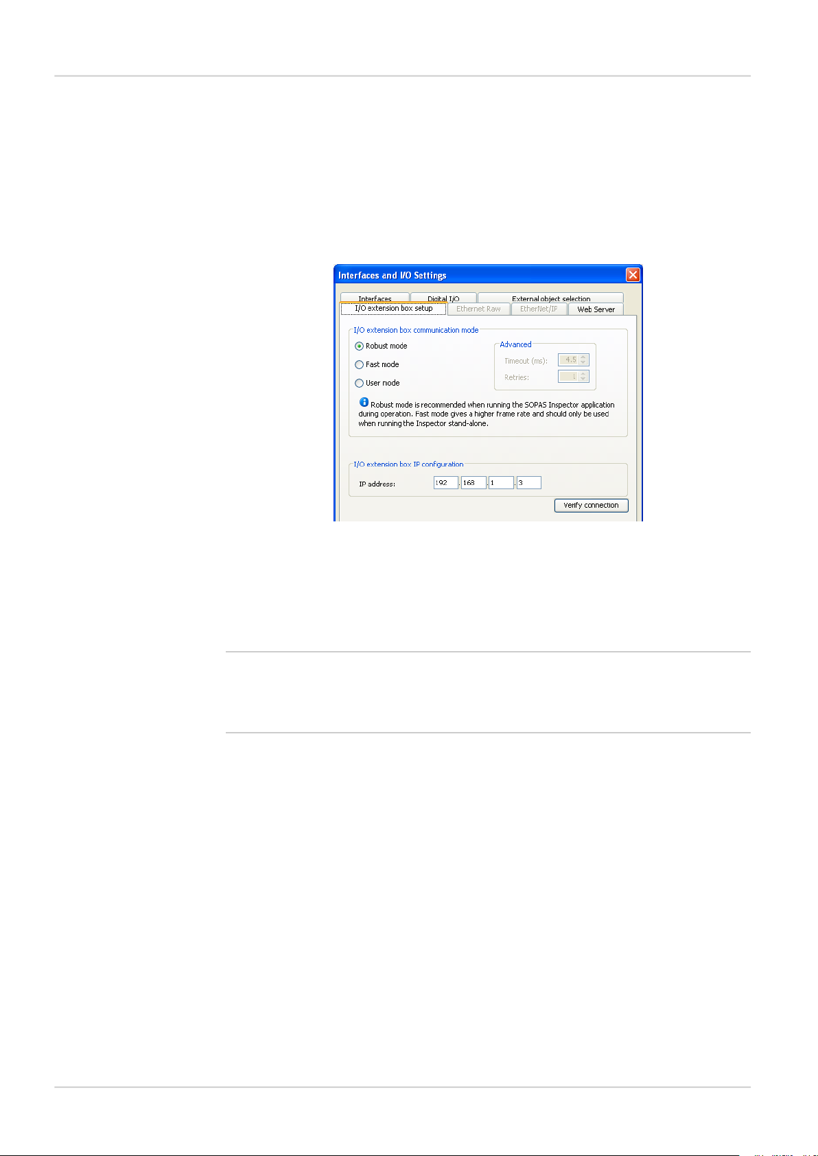
2.2 Configuration of the IP address on the I/O extension box ................. 8
2.2.1 Basic configuration of the IP address ............................ 9
2.3 Setup of the I/O extension box in the SOPAS Engineering Tool (ET)
application ................................................................................ 9
2.3.1 Enabling the I/O extension box ................................... 10
2.4 Input and output connections .................................................... 10
2.4.1 Special conditions during startup ............................... 10
2.4.2 Connection to the I/O extension box lost during opera-
tion ........................................................................ 11
2.4.3 Object selection with I/O extension box ....................... 11
2.4.4 Timing issues .......................................................... 11
2.4.5 Use of the digital outputs for logic .............................. 11
2.4.6 Change of Modules in the I/O extension box ................ 11
2.5 Troubleshooting ....................................................................... 11
2.5.1 The I/O LED flashes 10 times .................................... 11
2.5.2 No contact with the I/O extension box ......................... 11
2.5.3 High number of unanswered requests to the I/O exten-
sion box .................................................................. 12
3Web interface ...................................................................................... 13
3.1 Introduction ............................................................................. 13
3.2 Get results via Web API ............................................................. 13
3.2.1 Live image ............................................................... 13
3.2.2 Detailed results ....................................................... 13
3.2.3 Synchronize live image with result .............................. 14
3.2.4 Logged images ........................................................ 14
3.2.5 Statistics ................................................................. 15
3.3 Control the sensor via Web API ................................................... 15
3.3.1 Basic principles ....................................................... 15
3.3.2 Command syntax ..................................................... 15
3.3.3 Current reference object ........................................... 16
3.3.4 Backup and restore configuration ............................... 16
3.4 Create custom web pages .......................................................... 17
3.4.1 Example: Display live image ....................................... 19
3.5 Handle the Web API .................................................................. 21
4Ethernet Raw ...................................................................................... 22
4.1 Introduction ............................................................................. 22
4.1.1 Port interval ............................................................ 22
4.2 Get results via Ethernet Raw ...................................................... 22
4.2.1 TCP versus UDP ....................................................... 22
4.2.2 ASCII versus binary ................................................... 22
4.2.3 Attributes ................................................................ 23
4.2.4 Example formatting strings ........................................ 23
4.3 Control the sensor via Ethernet Raw ........................................... 26
4.3.1 Basic principles ....................................................... 26
4.3.2 Command syntax ..................................................... 26
3
©SICK AG • Identification & Measuring • www.sick.com • All rights reserved
Subject to change without notice
8015726/ZPP7/2018-
09
Inspector PIM60
Reference Manual
Inspector PIM

4.3.3 Select reference object ............................................. 27
4.3.4 Image triggering ....................................................... 27
4.3.5 Single port solution .................................................. 27
5EtherNet/IP ......................................................................................... 28
5.1 Introduction ............................................................................. 28
5.2 Get results via EtherNet/IP ........................................................ 28
5.2.1 Attributes ................................................................ 28
5.2.2 Example formatting strings ........................................ 28
5.3 Control the sensor via EtherNet/IP .............................................. 33
5.3.1 Basic principles ....................................................... 34
5.3.2 Command syntax ..................................................... 34
5.3.3 Select reference object ............................................. 34
5.3.4 Image triggering ....................................................... 35
5.3.5 Input assemblies, result channel ................................ 35
5.3.6 Assemblies command channel ................................... 36
Appendix 38
AResult output formatting ...................................................................... 39
A.1 XML based formatting ............................................................... 39
A.2 XML formatting ........................................................................ 39
A.3 Container specific tags .............................................................. 40
A.3.1 General tags ............................................................ 49
A.3.2 Attributes ................................................................ 50
BCommand channel ............................................................................... 52
B.1 Command syntax ..................................................................... 52
B.1.1 Commands ID numbers for EtherNet/IP ...................... 53
B.2 Command channel index handling .............................................. 54
B.2.1 Introduction ............................................................. 54
B.2.2 Blob indexing ........................................................... 54
B.2.3 Bead indexing .......................................................... 54
B.2.4 Polygon indexing ...................................................... 54
B.2.5 Tools indexing .......................................................... 54
B.3 Command descriptions ............................................................. 54
B.4 Error codes ............................................................................. 74
B.5 Version information .................................................................. 77
B.6 Command examples ................................................................. 77
B.6.1 Command examples Ethernet Raw ............................. 77
CRestore configuration over Web API ...................................................... 79
C.1 Restore configuration ............................................................... 79
C.2 Create session cookie ............................................................... 79
C.3 Login ...................................................................................... 79
C.4 Prepare restore mode ............................................................... 80
C.5 Transfer restore file to device ..................................................... 80
C.6 Device restart .......................................................................... 80
Index ............................................................................................................ 81
8015726/ZPP7/2018-
09
©SICK AG • Identification & Measuring • www.sick.com • All rights reserved
Subject to change without notice
4
Reference Manual
Inspector PIM60
Inspector PIM

Introduction

1Introduction
The Reference Manual is a complement to the Operating Instructions for Inspector PIM60
and covers the functionality of all product variants.
The Reference Manual contains detailed information about the interfaces including syntax
and available functionality. It focuses on Inspector PIM60 specific topics and does not describe
the basic technology behind each interface.
The details of the result output formatting and the contents and syntax of the command
channel are shared by several interfaces. They are described in an appendix valid for all rel-
evant interfaces.
For instructions on configuring the interfaces, refer to the Operating Instructions.
1.1 Interfaces overview
The Reference Manual contains detailed information for the following interfaces:
•I/O Extension Box is used to increase the number of available input and output connections
•Web API interface is intended for integration with external HMI implementations, and for
customized web pages on the Inspector
•Ethernet Raw interface is intended for integration with external PLC equipment
•EtherNet/IP interface is intended for integration with external PLC equipment following the
EtherNet/IP communication standard
1.2 Intended readers
The intended readers of the Reference Manual are users working with integration between
the Inspector PIM60 and other equipment, for example PLC programmers and customized
human machine interface (HMI) developers.
The readers are assumed to have knowledge about the Inspector PIM60 product and features
as described in the Operating Instructions for Inspector PIM60. The readers are also assumed
to have knowledge about the basic functionality of the technology of the interfaces used for
the integration.
8015726/ZPP7/2018-
09
©SICK AG • Identification & Measuring • www.sick.com • All rights reserved
Subject to change without notice
6
Reference Manual
Introduction
Introduction
Inspector PIM

Interfaces

2I/O extension box
The Inspector PIM60 can be connected to an I/O extension box that increases the number
of digital inputs and outputs. The I/O Extension box is available as an accessory from SICK.
This section covers how the I/O extension box is connected to the Inspector, and how it is
configured.
The following basic steps are required to use the I/O extension box with the Inspector. Details
about the steps are found in the subsequent sections.
1. Connect the I/O extension box to the network.
2. Configure the IP address of the I/O extension box to match the settings of the network,
and the Inspector.
3. Enter the IP address of the I/O extension box in the SOPAS Engineering Tool (ET) application.
4. Activate the inputs and/or outputs on the I/O extension box depending on the application.
Note
The SOPAS Engineering Tool (ET) application should be closed or set to offline when the power
to the I/O box is disconnected. The I/O extension box needs to be restarted if the IP address
is changed or if the connections to the inputs and outputs on the box are changed.
2.1 Physical network connection
To minimize network latency, it is recommended that the I/O extension box is connected
directly to the Inspector. The I/O box has a network switch so that a PC running SOPAS Engin-
eering Tool (ET) can be connected via the I/O box.
InspectorI/O Extension box
PC with SOPAS
Engineering Tool
(ET)
Figure 2.1 Physical network connection
2.2 Configuration of the IP address on the I/O extension box
This section briefly describes how to configure the I/O extension box for operation with the
Inspector. For details, please refer to the user manual delivered with the I/O extension box.
The IP address of the I/O extension box must be compatible with the addresses of the Inspect-
or and of the PC. For details of how to set and view the IP address of the Inspector, please
refer to the Operating Instructions for Inspector PIM60.
The following is an example of how the IP addresses can be configured for the Inspector, the
I/O box and the PC.
PCI/O Extension BoxInspector PIM60
192.168.1.30192.168.1.3192.168.1.110
8015726/ZPP7/2018-
09
©SICK AG • Identification & Measuring • www.sick.com • All rights reserved
Subject to change without notice
8
Reference Manual
I/O extension box
Interfaces
Inspector PIM

2.2.1 Basic configuration of the IP address
The address selection switch on the I/O extension box configures the host part of the IP ad-
dress, that is, the last of the four parts of the IP address. By default, the first three parts of
the address (also known as the network address) are set to 192.168.1. If the switch is set
to a value other than 0 (all switches set to Off) or 255 (all switches set to On), the I/O extension
box will use the host part of the IP address assigned by the switch.
Figure 2.2 Example
The setting above configures the I/O extension box to have a host ID of 3 corresponding to
the binary value “00000011” where switch 1 is bit 0 (LSB) and switch 8 is bit 7 (MSB). The
I/O box will then have an IP address of 192.168.1.3.
Advanced configuration of the IP address
If the network part of the IP address must be changed from the default 192.168.1 for the
I/O extension box, the internal web server of the I/O extension box can be used. For details
please refer to the manual delivered with the I/O extension box.
2.3 Setup of the I/O extension box in the SOPAS Engineering Tool
(ET) application
The communication with the I/O extension box is configured using the Interfaces and I/O Settings
dialog from the InspectorPIM60 menu. Check the Digital I/O and I/O extension boxes in the Inter-
faces tab. The I/O extension box is disabled if EtherNet/IP is selected in the same tab.
Figure 2.3 I/O Extension Box setup
Communication mode
It is possible to adjust the way that the Inspector is communicating with the I/O extension
box. The settings are made in the I/O extension box setup tab in the Interfaces and I/O Settings
dialog from InspectorPIM60 menu. There are three modes available:
• Robust mode. This is the default communication mode, and it is the recommended one if
the Inspector is connected to the SOPAS Engineering Tool (ET) application during operation.
• Fast mode. This mode allows the Inspector to operate at a higher frame rate but there is
a risk that some data in the communication with the I/O extension box is lost if there is
high load on the network. This mode shall not be used if the Inspector is connected to the
SOPAS Engineering Tool (ET) application during operation.
• User mode. This is the advanced communication mode where it is possible to configure
the number of retries that the Inspector performs, and the timeout for each retry. The
timeout is the time (in milliseconds) that the Inspector is waiting for a reply from the I/O
extension box for a request to set outputs or read inputs.
9
©SICK AG • Identification & Measuring • www.sick.com • All rights reserved
Subject to change without notice
8015726/ZPP7/2018-
09
Interfaces
I/O extension box
Reference Manual
Inspector PIM

IP configuration
To be able to connect to the I/O extension box, the IP address of the I/O extension box must
be specified in the SOPAS Engineering Tool (ET) application.
To specify the IP address of the I/O extension box:
1. Open the Interfaces and I/O Settings dialog from the InspectorPIM60 menu. Enter the selected
IP address of the I/O extension box setup tab in the four fields separated with dots.
2. Click Apply to store the settings.
Figure 2.4 Set up mode and IP address
Verify connection
It is possible to verify that the connection to the I/O extension box can be established by
clicking the Verify connection button. The SOPAS Engineering Tool (ET) application will then try to
connect to the I/O extension box, and a message will be displayed informing if the I/O exten-
sion box was found.
Note
It is possible to configure the Inspector for use with the I/O extension box even when the I/O
extension box is not available. As soon as the Inspector detects the I/O extension box on the
network, it will connect to it and start using it as configured.
2.3.1 Enabling the I/O extension box
The use of the inputs and outputs on the I/O extension box is enabled on the Digital I/O tab
of the Interface and I/O Settings dialog from the InspectorPIM60 menu.
2.4 Input and output connections
When delivered, the I/O extension box contains 4 digital inputs and 8 digital outputs. The
digital outputs can be expanded to 16, and the digital inputs of the Inspector PIM60 can be
extended to 5.
Please refer to the manual delivered with the I/O extension box for details on how to connect
the power supply to the box, and where to find the digital inputs and outputs.
2.4.1 Special conditions during startup
The following applies if the Inspector is configured to use the inputs of the I/O extension box
for object selection:
If the I/O extension box is not available when the Inspector starts up, the Inspector will use
the last reference object that was selected in the SOPAS Engineering Tool (ET) application before
8015726/ZPP7/2018-
09
©SICK AG • Identification & Measuring • www.sick.com • All rights reserved
Subject to change without notice
10
Reference Manual
I/O extension box
Interfaces
Inspector PIM

data was saved to flash. Once the I/O extension box is available, the Inspector will read the
inputs of the box, and select the corresponding reference object.
2.4.2 Connection to the I/O extension box lost during operation
If the connection to the I/O extension box is lost during operation, the last status of the inputs
on the box will be used until the connection is re-established.
2.4.3 Object selection with I/O extension box
The status of the inputs on the I/O extension box is checked in the end of each inspection
cycle. If the Inspector is configured to use external image trig, the status of the external inputs
will only be checked when an image trig signal has been received.
2.4.4 Timing issues
The digital outputs on the I/O extension box shall be read at minimum delay time as displayed
in the SOPAS Engineering Tool (ET) application.
2.4.5 Use of the digital outputs for logic
The digital outputs on the I/O extension box are not guaranteed to be jitter-free. It is not re-
commended to use these outputs for direct control of other devices. The I/O extension box
shall be connected to a PLC for process control.
2.4.6 Change of Modules in the I/O extension box
The Inspector PIM60 supports I/O extension box configurations with up to 16 digital outputs
and 5 digital inputs (The standard configuration of the I/O extension box contains 8 digital
outputs and 4 digital inputs.). The configuration of an I/O extension box can be changed by
adding/removing I/O modules to/from the I/O extension box. I/O modules are available as
an accessory from SICK. For details about Accessories Ordering information see the Operating
Instructions for Inspector PIM60.
Perform the following steps to connect and use more I/O modules:
1. Close the SOPAS Engineering Tool (ET) application.
2. Disconnect the power from the I/O extension box.
3. Connect the additional I/O modules (inputs and/or outputs) to the I/O extension box.
Please refer to the manual delivered with the I/O extension box for details.
4. Re-connect the power to the I/O extension box.
5. Re-start the SOPAS Engineering Tool (ET) application.
The additional digital outputs are now be available in the SOPAS Engineering Tool (ET) application.
2.5 Troubleshooting
2.5.1 The I/O LED flashes 10 times
If the power to the I/O extension box has been disconnected for a longer period of time, the
internal clock in the box will be reset. The I/O LED on the box will then flash 10 times in red.
This is not a serious error, and the I/O extension box can still be used together with the In-
spector without any problems.
2.5.2 No contact with the I/O extension box
Ensure that the network card on the PC has the same network address, for instance
192.168.1, as the I/O extension box. The host part of the IP address (that is the last number
in the IP address) must not be the same as for the I/O extension box or the Inspector.
There are two tools available in Windows to check the network connection and the IP settings:
•Ping. Open the command prompt, and type ping followed by the IP address of the I/O exten-
sion box. If the I/O extension box is available the following text will be displayed: Reply from
x.x.x.x (where x.x.x.x is the IP address of the I/O extension box). If the I/O extension box
11
©SICK AG • Identification & Measuring • www.sick.com • All rights reserved
Subject to change without notice
8015726/ZPP7/2018-
09
Interfaces
I/O extension box
Reference Manual
Inspector PIM

could not be found an error message is displayed, for instance Request timed out or Destination
host unreachable.
Example: ping 192.168.1.3
•Ipconfig. Open the command prompt and type ipconfig. The current status for the network
cards on the PC will then be displayed. Ensure that the network settings are corresponding
to the setting for the I/O extension box. The current IP address for the Inspector can be
viewed by selecting Device Info from the InspectorPIM60 menu.
The web browser on the PC must be configured not to use a proxy when communicating with
the web server in the I/O extension box.
2.5.3 High number of unanswered requests to the I/O extension box
The advanced communication mode, User mode, can be used to fine tune the communication
with the I/O extension box. It is recommended to try to increase the timeout as a first step,
and if this does not work, try to increase the number of retries. Increasing the number of retries
will reduce the inspection speed.
If the problem persists even if the timeout and the number of retries have been increased,
verify that the network topology does not block the use of UDP packets.
8015726/ZPP7/2018-
09
©SICK AG • Identification & Measuring • www.sick.com • All rights reserved
Subject to change without notice
12
Reference Manual
I/O extension box
Interfaces
Inspector PIM

3Web interface
3.1 Introduction
The Inspector PIM60's web interface can be used in two different ways:
• Users can use a web browser to open web pages served by the Inspector's built-in web
server.
The Inspector PIM60 is delivered with a set of web pages for handling the Inspector, but
you can also create custom web pages that can be accessed through the Inspector's built-
in web server. When you create custom web pages, all functions available through the
Web API can be used.
• Custom applications running on separate systems can use the Web API to directly retrieve
images and results, and retrieve and set parameters on the Inspector.
Details on how to manage and access the web pages served by the Inspector is described
in the Operating Instructions for Inspector PIM60.
Note
All URLs on the Inspector are case sensitive. For example, trying to use /LiveImage.jpg to
retrieve the live image will not work.
3.2 Get results via Web API
3.2.1 Live image
The live image can be retrieved through the Web API by a live image request using the URL:
http://<IP-address>/LiveImage.jpg
The response to the request is a data buffer containing a JPEG image.
If the image is not available, an empty image is returned with a smaller size than a normal
image.
Note
The live image is not available when SOPAS is connected to the Inspector PIM60.
Live image response can be much slower when activating the Send to FTP feature.
Example URLs
Request a live image without overlay graphics:
http://192.168.1.110/LiveImage.jpg
The response to the request is a JPEG image.
Request a live image with overlay graphics:
http://192.168.1.110/LiveImage.jpg?ShowOverlay
Request a live image with simplified overlay graphics:
http://192.168.1.110/LiveImage.jpg?SimplifiedOverlay
3.2.2 Detailed results
The result string, containing the results from the last analyzed image, can be retrieved through
the Web API by a request using the URL:
http://<IP-address>/CmdChannel?gRES
The response is a string that has the following syntax:
rgRES <errorCode> <resultString>
13
©SICK AG • Identification & Measuring • www.sick.com • All rights reserved
Subject to change without notice
8015726/ZPP7/2018-
09
Interfaces
Web interface
Reference Manual
Inspector PIM

The result string is the string that is output over Ethernet, and which is defined in the Ethernet
Results Output dialog.
For example, if the current configuration has an object locator and an edge pixel counter,
and Ethernet Results Output uses the default example formatting string, the Inspector would
return the following string:
rgRES 0 194
Image_number: 9639
Object_locator.
Located: 1
Score: 99.00
Scale: 1.00
Position_(X,Y): (237.78,202.05)
Rotation: 20.05
-------------------------
Edge_pixel_counter_1
Decision: 1
Pixels: 724
The result is not synchronized with the live image. This means that in some situations, if you
retrieve a live image and after that a result string, that string may not contain the result for
the retrieved image, but for an image captured and analyzed later. See Section 3.2.3, “Syn-
chronize live image with result” (page 14) for a solution.
3.2.3 Synchronize live image with result
To synchronize the live image with the result, you need to assign an id to the image. The id
can be up to 16 characters long and can consist of numbers, letters, and special characters.
http://<IP-address>/LiveImage.jpg?id=<ID>
The result for the live image assigned to the <ID> can be listed using the following syntax:
http://<IP-address>/ImageResult?id=<ID>
Note
The image might not update if this method is used due to caching, see Section 3.4.1, “Ex-
ample: Display live image” (page 19) for more information.
Example URLs
Request a live image without overlay graphics and assign an id to the image:
http://192.168.1.110/LiveImage.jpg?id=ID_ABC123
Request a live image with overlay graphics and assign an id to the image:
http://192.168.1.110/LiveImage.jpg?ShowOverlay&id=ID_ABC123
Request a live image with simplified overlay graphics and assign an id to the image:
http://192.168.1.110/LiveImage.jpg?SimplifiedOverlay&id=ID_ABC123
3.2.4 Logged images
Logged images can be retrieved using the URL:
http://<IP-address>/LogImage.jpg?00
where the argument "00" is the image number. The image number is two digits in the range
[00, 29]. The device keeps writing to the log and therefore the log first has to be locked to
be able to retrieve an image. This is done by using the URL http://<IP-address>/LockLog
The response to the request is a JPEG image. An empty image with a smaller size than a
normal image is returned if no log image is available for a certain position.
To start logging images again the log has to be unlocked first and this is done by using the
URL http://<IP-address>/LockLog?Unlock
8015726/ZPP7/2018-
09
©SICK AG • Identification & Measuring • www.sick.com • All rights reserved
Subject to change without notice
14
Reference Manual
Web interface
Interfaces
Inspector PIM

Example URLs
http://192.168.1.110/LockLog
http://192.168.1.110/LockLog?Unlock
Retrieve a logged image without overlay graphics:
http://192.168.1.110/LogImage.jpg?00
Retrieve a logged image with overlay graphics:
http://192.168.1.110/LogImage.jpg?00&ShowOverlay
Retrieve a logged image with simplified overlay graphics:
http://192.168.1.110/LogImage.jpg?00&SimplifiedOverlay
3.2.5 Statistics
To retrieve statistics using the command channel, execute the following command:
gSTAT
Statistics can also be retrieved using the URL:
http://<IP-address>/CmdChannel?gSTAT
The response is rgSTAT 0 followed by an XML formatted string. To read the response in an
web browser, change the view in the web browser to reflect the source code.
Note
The statistic response is only for the active reference object.
3.3 Control the sensor via Web API
The Web API supports using the command channel for reading and updating parts of the
device configuration.
The Web API also supports the functionality to do a backup of the device configuration to a
file and to restore the configuration again. This is a convenient way to handle configurations
without installing and using SOPAS Engineering Tool (ET).
3.3.1 Basic principles
The command channel has a set of basic principles:
• Only one command at a time can be executed.
• Inspector PIM60 responds to each command with a response that includes the result of
the command as well as error codes.
• A specific task to control the Inspector PIM60 includes the command together with its
parameters, see list of command types and parameters in Appendix B, “Command chan-
nel” (page 52).
• Writing a parameter can typically only be done when the device is in Edit mode. Reading
a parameter can be done in both Edit and Run mode.
• It is possible to block configuration changes by deselecting Allow changes via Web Server in
the Web Server tab in the dialog Interfaces and I/O Settings in InspectorPIM60 menu.
3.3.2 Command syntax
The Web API command channel has the following syntax:
http://<IP-address>/CmdChannel?<command>_<identifier>_<argument
1>_<argument 2>..._<argument N>
The ACK message has the following syntax:
<ACK Command> <identifier> <errorCode> <returnValue1> <returnValue2> ...
<returnValueN> <errorMessage>
The command is sent as an ASCII string. The combination of a command with its parameters
will either change the device configuration or fetch information from the device. For more
15
©SICK AG • Identification & Measuring • www.sick.com • All rights reserved
Subject to change without notice
8015726/ZPP7/2018-
09
Interfaces
Web interface
Reference Manual
Inspector PIM

command examples see Section B.1, “Command syntax” (page 52) and Section B.6, “Com-
mand examples” (page 77).
Note
The command syntax differs from other interfaces where the initial part
http://<IP-address>/CmdChannel? is added and all space characters (" ") are replaced
by an underscore character ("_"). The ACK messages still contain spaces.
Example URL
The successful execution of the following command
http://192.168.1.110/CmdChannel?sINT_1_1
will perform the command (to select reference object with index 1) and then return the fol-
lowing string:
rsINT 1 0
while a failed command may return:
rsINT 1 8101 Ref bank index is not used.
3.3.3 Current reference object
The reference image of the current reference object can be retrieved using the URL:
http://<IP-address>/ActiveReferenceImage.jpg
The response to the request is a JPEG image.
The reference image of any reference object in the Inspector can be retrieved using the URL:
http://<IP-address>/getRefObject?0
where the argument "0" is the index of the reference object. The object index that corresponds
to each reference object can be found in the Reference object list in the Main view.
The response to the request is a JPEG image. An empty image with a smaller size than a
normal image is returned if no reference object is available for a certain position.
Example URL
http://192.168.1.110/ActiveReferenceImage.jpg
http://192.168.1.110/getRefObject?1
3.3.4 Backup and restore configuration
It is possible to backup and restore the device configuration through the Web API. This is the
same functionality also available through the standard web pages of the Web Server interface.
The backup data contains the device name and reference objects including corresponding
inspection and interface settings.
Note
The backup and restore functionality of the Web Server and the Web API corresponds to the
Export Sopas Parameter backup and Import Sopas Parameter backup in the InspectorPIM60 menu.
The backup data used by the Web API is saved as .sbp files, which can be imported to and
exported from SOPAS Engineering Tool (ET). The Web API can not use .sdv files.
Backup configuration
The URL to export a configuration is http://<IP-address>/backup_config?config1
Example URL:
http://192.168.1.110/backup_config?config1
The result of the request is an .spb file containing the device configuration. This file can be
stored in the file system of the receiving unit and used later in the restore procedure.
8015726/ZPP7/2018-
09
©SICK AG • Identification & Measuring • www.sick.com • All rights reserved
Subject to change without notice
16
Reference Manual
Web interface
Interfaces
Inspector PIM

The Web Server standard web pages requires a login to perform a backup. A login is not re-
quired when doing a backup through the Web API.
Restore configuration
The restore operation takes a device configuration created with the backup functionality and
replaces the current configuration with the configuration in the backup file.
The operation is a multiple step procedure that requires a login. The details of the procedure
is described in Appendix C, “Restore configuration over Web API” (page 79).
The operation may take several minutes and the Inspector PIM60 is automatically restarted
after the configuration has been transferred to the Inspector PIM60.
Warning
During the restore operation the device is set in a special restore mode only expecting restore
operation requests. Operations and requests via other interfaces like field buses, SOPAS En-
gineering Tool (ET), or other web browsers shall then be avoided since they may interfere with
the restore operation.
3.4 Create custom web pages
When creating customized web pages to be stored on and served by the Inspector, you use
the Web API to display images, retrieve results and settings, and change parameters in the
Inspector.
The functions that use the command channel (retrieving results, and getting and setting
parameters) returns the result in text strings, which you need to parse in order to extract the
information that you are interested in. To make this easier, the Inspector PIM60 provides a
JavaScript that you can use in your web pages, and that helps parsing the results.
You use the functions by including the script file inspector.js in your page, and then create
an Inspector object in your own script.
Note
The inspector.js script uses JQuery, so you need to also include the provided jquery.js
script. For more information on JQuery, see www.jquery.com.
<html>
<head>
<title>Custom page</title>
<script type="text/javascript" src="/jquery.js"></script>
<script type="text/javascript" src="/inspector.js"></script>
<script type="text/javascript">
//<!--
var inspector = new Inspector();
...
//-->
</script>
...
The Inspector object has methods that correspond to the commands that can be sent over
the command channel. The available methods are listed in Table 3.1, “Methods in inspect-
or.js” (page 19). When using these methods, you pass the same arguments as when using
the "raw" command channel commands, as described in Appendix B, “Command chan-
nel” (page 52).
The Inspector object returns the (parsed) command response through a callback function.
To use the response, you define a function that takes a single argument – the response object
– and pass that function as an argument to the Inspector's method. In the function you can
17
©SICK AG • Identification & Measuring • www.sick.com • All rights reserved
Subject to change without notice
8015726/ZPP7/2018-
09
Interfaces
Web interface
Reference Manual
Inspector PIM

then check whether the command succeeded, and retrieve the information you are interested
in.
For example, to select the first reference object in the current configuration (with index 0),
you would call:
// First, define a callback function that handles the result
function setRefObjResponse(response) {
if (response.httpStatus != 200 || response.errorCode != 0) {
alert(response.errorMessage);
}
};
// Then, call the inspector object's setInt function
// with the arguments:
// identifier = 1 for "Set reference object"
// arg1 = 0, for reference object with index 0
function setRefObj() {
inspector.setInt(1, 0, setRefObjResponse );
};
Tip
As an experienced JavaScript developer, you would probably define your callback function
as an anonymous function directly in the call to the inspector methods:
inspector.setInt(1, 0, function(response) {
if (response.httpStatus != 200 || response.errorCode != 0) {
alert(response.errorMessage);
}
});
The content of the response object depends on the function that you called, as well as on
the outcome of the command. The following attributes are common for all methods:
type The response type, which is basically the same as the command type.
See Table B.3, “Command ID numbers - for EtherNet/IP” (page 54).
errorCode If non-zero, the command failed for some reason. See Section B.4, “Error
codes” (page 74).
errorMessage A text message that describes the error. Exists only if the command failed.
httpStatus The HTTP status code. If this is not set to 200, the HTTP request failed
and the Inspector didn't return any result at all.
The following table lists the attributes that are specific to the called method:
8015726/ZPP7/2018-
09
©SICK AG • Identification & Measuring • www.sick.com • All rights reserved
Subject to change without notice
18
Reference Manual
Web interface
Interfaces
Inspector PIM

Table 3.1 Methods in inspector.js
Response attributesCorresponding com-
mand
Method
protocolVersiongVERgetVersion(callback)
modegMODgetMode(callback)
values[0]sMODsetMode(mode, callback)
identifier
values[0 ... n]
gINTgetInt(identifier, arg1, ..., argn, callback)
identifier
values[0 ... n]
sINTsetInt(identifier, arg1, ..., argn, callback)
identifier
value
gSTRgetString(identifier, arg1, ..., argn, callback)
identifieraACTperformAction(identifier, args, callback)
-TRIGtrig(callback)
resultStringgRESgetResult(callback)
-/LockLoglockLog(callback)
-/LockLog?UnlockunlockLog(callback)
The result string returned by the getResult() method is the same string that is output over
Ethernet, and which is defined in the Ethernet Results Output dialog.
Note
Do not make another call to the Inspector before the current call has returned a response.
If you do, the current command will be interrupted and will not return any response at all,
making it difficult to figure out whether or not the command was performed on the Inspector.
Normally, this is not a problem, but if you are using timed triggers, you should make sure
that the triggered functions don't interrupt any commands that may currently be performed
on the Inspector.
3.4.1 Example: Display live image
To display the current live image, simply include the image from /LiveImage.jpg on your
web page:
...
<image src="/LiveImage.jpg"/>
..
This image will not update automatically, so you could add some JavaScript that makes the
live image refresh with a certain interval.
...
<script type="text/javascript">
//<!--
function refreshLiveImage() {
var image = document.getElementById("liveImage");
image.src = "/LiveImage.jpg?ShowOverlay" + (new Date()).getTime() );
// The (new Date()...) is a trick to make the browser
// retrieve the image from the Inspector and not from cache
setTimeout(refreshLiveImage, 500);
};
19
©SICK AG • Identification & Measuring • www.sick.com • All rights reserved
Subject to change without notice
8015726/ZPP7/2018-
09
Interfaces
Web interface
Reference Manual
Inspector PIM

// Initiate the image and refresh when page is loaded
window.onload = function(){
refreshLiveImage();
};
//-->
</script>
...
</head>
<body>
<img id="liveImage" src="/LiveImage.jpg?ShowOverlay"/>
</body>
Alternatively, you can use the live image component that is used on the Inspector's default
Live image page, which has automatic refresh, setting for refresh interval, and magnifier.
Figure 3.1 Inspector's default live image component
To use the default live image component, include the userliveimage.js script in your page,
and call the sickLiveImage() function as in the following example:
<html xmlns="http://www.w3.org/1999/xhtml">
<head>
<title>Live Image</title>
<script type="text/javascript" src="/jquery.js"></script>
<script type="text/javascript" src="/userliveimage.js"></script>
<script type="text/javascript">
//<!--
$(document).ready(function () {
$("#liveImage").sickLiveImage({
width: 640,
height: 480,
nocache: true,
minInterval: 500,
refreshInterval: 1000,
magnifier: true,
imgUrl: "/LiveImage.jpg",
refreshText: "Refresh interval"
});
});
//-->
</script>
</head>
<body>
<div id="liveImage"></div>
</body>
</html>
8015726/ZPP7/2018-
09
©SICK AG • Identification & Measuring • www.sick.com • All rights reserved
Subject to change without notice
20
Reference Manual
Web interface
Interfaces
Inspector PIM
Other manuals for Inspector PIM60
1
This manual suits for next models
16
Table of contents
Other SICK Accessories manuals

SICK
SICK GTE20 User manual

SICK
SICK KTS User manual

SICK
SICK LD-MRS 400001S01 User manual

SICK
SICK Bulkscan User manual

SICK
SICK deTec4 C4C-EV03030A10000 User manual

SICK
SICK OL1 User manual

SICK
SICK Flexi Loop User manual

SICK
SICK GLS6 User manual

SICK
SICK KTS Prime User manual

SICK
SICK DL100 Pro User manual

SICK
SICK MZT6-03VPS-KPX User manual

SICK
SICK KTS Prime User manual

SICK
SICK MPB10 User manual

SICK
SICK GRTE18 24 Series User manual

SICK
SICK DL100 Pro User manual

SICK
SICK UC12 User manual

SICK
SICK WTV4-3 V-optic User manual

SICK
SICK RMS1000 User manual

SICK
SICK WL34 User manual

SICK
SICK CS81-P3612S02 User manual