SICK MultiPulse WTB4-3P2100S14 User manual

OPERATING I N S T R U C T I O N
4
MultiTask
en / de / fr / it / pt / es / zh / ja / ru
SICK AG, Erwin-Sick-Strasse 1, D-79183 Waldkirch
8019200.126R
2006/42/EG
NO
SAFETY

Photoelectric proximity sensor
Operating instructions
1 Safety notes
■Read the operating instructions before commissioning.
■Connection, mounting, and setting may only be performed by trained specialists.
■Not a safety component in accordance with the EU Machinery Directive.
■UL: Only for use in applications in accordance with NFPA 79. These devices shall
be protected by a 1 A fuse suitable for 30 V DC. Adapters listed by UL with connec‐
tion cables are available. Enclosure type 1
■When commissioning, protect the device from moisture and contamination.
■These operating instructions contain information required during the life cycle of
the sensor.
2 Correct use
The MultiPulse WTB4-3 is an opto-electronic photoelectric proximity sensor (referred to
as "sensor" in the following) for the optical, non-contact detection of objects. If the pro‐
duct is used for any other purpose or modified in any way, any warranty claim against
SICK AG shall become void.
Photoelectric proximity sensor with background suppression.
Image: A
3 Commissioning
1 Mount the sensor using a suitable mounting bracket (see the SICK range of acces‐
sories).
Note the sensor's maximum permissible tightening torque of 0.8 Nm.
2 The sensors must be connected in a voltage-free state (Uv = 0 V). The information
in the graphics [B] must be observed, depending on the connection type:
– Male connector connection: pin assignment
8019200.126R | SICK
Subject to change without notice 1

+ (L+)
-(M)
Q
brn
blu
blk
1
3
4
Image: B
Only apply voltage/switch on the power supply (Uv > 0 V) once all electrical connec‐
tions have been established. The green LED indicator lights up on the sensor.
Explanations of the connection diagram (Graphic B):
MultiPulse WTB4-3P (PNP: load -> M)
Output oscillates at 10 Hz if an object is located within the fixed sensing range 30
to 100 mm. Output switches off if an object is located within the range 0 to 30 mm
and > 100 mm.
3 Align the sensor with the object. Select the position so that the red emitted light
beam hits the center of the object. You must ensure that the optical opening (front
screen) of the sensor is completely clear [E]. We recommend making the adjust‐
ments using an object with a low remission.
Image: E
4 Sensor which it is not possible to set: The sensor is adjusted and ready for opera‐
tion. The fixed sensing range is 30 ... 100 mm.
Image: C
5 Fault diagnosis
Table indicates which measures are to be taken if the sensor stops working.
4
28019200.126R | SICK
Subject to change without notice

6 Table Fault diagnosis
LED indicator/fault pattern /
LED indicator/fault pattern
Cause /
Cause
Measures /
Measures
Green LED does not light up /
Green LED does not light up
No voltage or voltage below
the limit values /
No voltage or voltage below
the limit values
Check the power supply,
check all electrical connecti‐
ons (cables and plug connecti‐
ons) /
Check the power supply,
check all electrical connecti‐
ons (cables and plug connecti‐
ons)
Green LED does not light up /
Green LED does not light up
Voltage interruptions /
Voltage interruptions
Ensure there is a stable power
supply without interruptions /
Ensure there is a stable power
supply without interruptions
Green LED does not light up /
Green LED does not light up
Sensor is faulty /
Sensor is faulty
If the power supply is OK,
replace the sensor /
If the power supply is OK,
replace the sensor
Yellow LED flashes /
Yellow LED flashes
Sensor is still ready for opera‐
tion, but the operating conditi‐
ons are not ideal /
Sensor is still ready for opera‐
tion, but the operating conditi‐
ons are not ideal
Check the operating conditi‐
ons: Fully align the beam of
light (light spot) with the
object. / Clean the optical sur‐
faces . / Readjust the sensiti‐
vity / Check sensing range
and adjust if necessary; see
graphic F. /
Check the operating conditi‐
ons: Fully align the beam of
light (light spot) with the
object. / Clean the optical sur‐
faces . / Readjust the sensiti‐
vity / Check sensing range
and adjust if necessary; see
graphic F.
Yellow LED lights up, no object
in the path of the beam /
Yellow LED lights up, no object
in the path of the beam
/ Distance between the sen‐
sor and the background is too
short /
/ Distance between the sen‐
sor and the background is too
short
Reduce the sensing range,
see graphic F /
Reduce the sensing range,
see graphic F
Object is in the path of the
beam, yellow LED does not
light up /
Object is in the path of the
beam, yellow LED does not
light up
Distance between the sensor
and the object is too long or
sensing range is set too
short /
Distance between the sensor
and the object is too long or
sensing range is set too short
Increase the sensing range,
see graphic F /
Increase the sensing range,
see graphic F
7 Disassembly and disposal
The sensor must be disposed of according to the applicable country-specific regulati‐
ons. Efforts should be made during the disposal process to recycle the constituent
materials (particularly precious metals).
TABLE FAULT DIAGNOSIS 6
3
8019200.126R | SICK
Subject to change without notice

8 Maintenance
SICK sensors are maintenance-free.
We recommend doing the following regularly:
•Clean the external lens surfaces
•Check the screw connections and plug-in connections
No modifications may be made to devices.
Subject to change without notice. Specified product properties and technical data are
not written guarantees.
9 Technical data
WTB4-3P2100S14
Sensing range 30 ... 100 mm
Sensing range max. 30 ... 100 mm1)
Light spot diameter/distance 7 mm / 50 mm
Supply voltage VSDC 10 ... 30 V2)
Output current Imax. 100 mA
Max. switching frequency 2 Hz3)
Max. response time 250 ms4)
Enclosure rating IP 67
Protection class III
Circuit protection A,C,D5)
Ambient operating temperature -40 ... +60 °C
1) Object with 90 % remission (based on standard white DIN 5033)
2) Limit value: operation in short-circuit protection mains max. 8 A; residual ripple max.
5 Vss
3) With light / dark ratio 1:1
4) Signal transit time with resistive load
5) A = UV-connections reverse polarity protected
C = Interference suppression
D = outputs overcurrent and short-circuit protected
8 MAINTENANCE
48019200.126R | SICK
Subject to change without notice

Reflexions-Lichttaster
Betriebsanleitung
10 Sicherheitshinweise
■Vor der Inbetriebnahme die Betriebsanleitung lesen.
■Anschluss, Montage und Einstellung nur durch Fachpersonal.
■Kein Sicherheitsbauteil gemäß EU-Maschinenrichtlinie.
■UL: Nur zur Verwendung in Anwendungen gemäß NFPA 79. Diese Geräte müssen
mit einer für 30V DC geeigneten 1A-Sicherung abgesichert werden. Von UL gelis‐
tete Adapter mit Anschlusskabeln sind verfügbar. Enclosure type 1
■Gerät bei Inbetriebnahme vor Feuchte und Verunreinigung schützen.
■Diese Betriebsanleitung enthält Informationen, die während des Lebenszyklus des
Sensors notwendig sind.
11 Bestimmungsgemäße Verwendung
Die MultiPulse WTB4-3 ist ein optoelektronischer Reflexions-Lichttaster (im Folgenden
Sensor genannt) und wird zum optischen, berührungslosen Erfassen von Sachen einge‐
setzt. Bei jeder anderen Verwendung und bei Veränderungen am Produkt verfällt jegli‐
cher Gewährleistungsanspruch gegenüber der SICK AG.
Reflexionslichttaster mit Hintergrundausblendung.
Abb.: A
12 Inbetriebnahme
1 Den Sensor an einen geeigneten Befestigungswinkel montieren (siehe SICK-Zube‐
hör-Programm).
Maximal zulässiges Anzugsdrehmoment des Sensors von 0.8 Nm beachten.
2 Anschluss der Sensoren muss spannungsfrei (UV = 0 V) erfolgen. Je nach
Anschlussart sind die Informationen in den Grafiken [vgl. B] zu beachten:
– Steckeranschluss: Pinbelegung
5
8019200.126R | SICK
Subject to change without notice

+ (L+)
-(M)
Q
brn
blu
blk
1
3
4
Abb.: B
Erst nach Anschluss aller elektrischen Verbindungen die Spannungsversorgung (UV
> 0 V) anlegen bzw. einschalten. Am Sensor leuchtet die grüne Anzeige-LED.
Erläuterungen zum Anschlussschema (Grafik B):
MultiPulse WTB4-3P (PNP: Last -> M)
Ausgang schwingt mit 10 Hz, wenn sich ein Objekt im fixen Schaltbereich 30 ...
100 mm befindet. Ausgang schaltet aus, wenn sich ein Objekt im Bereich 0 ... 30
mm und > 100 mm befindet.
3 Sensor auf Objekt ausrichten. Positionierung so wählen, dass der rote Sendelicht‐
strahl in der Mitte des Objekts auftrifft. Es ist darauf zu achten, dass die optische
Öffnung (Frontscheibe) des Sensors vollständig frei ist [vgl. E]. Wir empfehlen, die
Einstellung mit einem Objekt von niedriger Remission vorzunehmen.
Abb.: E
4 Sensor ohne Einstellmöglichkeit: Sensor ist eingestellt und betriebsbereit. Der fixe
Schaltabstand beträgt 30 ... 100 mm.
Abb.: C
14 Fehlerdiagnose
Tabelle I zeigt, welche Maßnahmen durchzuführen sind, wenn die Funktion des Sensors
nicht mehr gegeben ist.
13
68019200.126R | SICK
Subject to change without notice

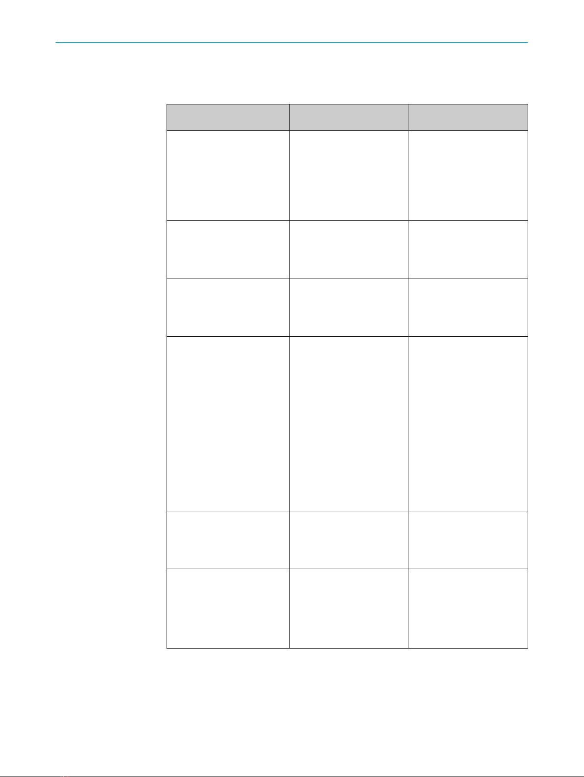
15 Tabelle Fehlerdiagnose
Anzeige-LED / Fehlerbild /
LED indicator/fault pattern
Ursache /
Cause
Maßnahme /
Measures
grüne LED leuchtet nicht /
Green LED does not light up
keine Spannung oder Span‐
nung unterhalb der Grenz‐
werte /
No voltage or voltage below
the limit values
Spannungsversorgung prüfen,
den gesamten elektrischen
Anschluss prüfen (Leitungen
und Steckerverbindungen) /
Check the power supply,
check all electrical connecti‐
ons (cables and plug connecti‐
ons)
grüne LED leuchtet nicht /
Green LED does not light up
Spannungsunterbrechungen /
Voltage interruptions
Sicherstellen einer stabilen
Spannungsversorgung ohne
Unterbrechungen /
Ensure there is a stable power
supply without interruptions
grüne LED leuchtet nicht /
Green LED does not light up
Sensor ist defekt /
Sensor is faulty
Wenn Spannungsversorgung
in Ordnung ist, dann Sensor
austauschen /
If the power supply is OK,
replace the sensor
gelbe LED blinkt /
Yellow LED flashes
Sensor ist noch betriebsbe‐
reit, aber die Betriebsbedin‐
gungen sind nicht optimal /
Sensor is still ready for opera‐
tion, but the operating conditi‐
ons are not ideal
Betriebsbedingungen prüfen:
Lichtstrahl (Lichtfleck) voll‐
ständig auf das Objekt aus‐
richten / Reinigung der opti‐
schen Flächen / Empfindlich‐
keit neu einstellen / Schaltab‐
stand überprüfen und ggf.
anpassen, siehe Grafik F. /
Check the operating conditi‐
ons: Fully align the beam of
light (light spot) with the
object. / Clean the optical sur‐
faces . / Readjust the sensiti‐
vity / Check sensing range
and adjust if necessary; see
graphic F.
gelbe LED leuchtet, kein Objekt
im Strahlengang /
Yellow LED lights up, no object
in the path of the beam
Abstand zwischen Sensor und
Hintergrund ist zu gering /
/ Distance between the sen‐
sor and the background is too
short
Schaltabstand verringern,
siehe Grafik F /
Reduce the sensing range,
see graphic F
Objekt ist im Strahlengang,
gelbe LED leuchtet nicht /
Object is in the path of the
beam, yellow LED does not
light up
Abstand zwischen Sensor und
Objekt ist zu groß oder Schalt‐
abstand ist zu gering einge‐
stellt /
Distance between the sensor
and the object is too long or
sensing range is set too short
Schaltabstand vergrößern,
siehe Grafik F /
Increase the sensing range,
see graphic F
16 Demontage und Entsorgung
Die Entsorgung des Sensors hat gemäß den länderspezifisch anwendbaren Vorschrif‐
ten zu erfolgen. Für die enthaltenen Wertstoffe (insbesondere Edelmetalle) ist im Rah‐
men der Entsorgung eine Verwertung anzustreben.
TABELLE FEHLERDIAGNOSE 15
7
8019200.126R | SICK
Subject to change without notice

17 Wartung
SICK-Sensoren sind wartungsfrei.
Wir empfehlen, in regelmäßigen Abständen
•die optischen Grenzflächen zu reinigen
•Verschraubungen und Steckverbindungen zu überprüfen
Veränderungen an Geräten dürfen nicht vorgenommen werden.
Irrtümer und Änderungen vorbehalten. Angegebene Produkteigenschaften und techni‐
sche Daten stellen keine Garantieerklärung dar.
18 Technische Daten
WTB4-3P2100S14
Schaltabstand 30 ... 100 mm
Schaltabstand max. 30 ... 100 mm6)
Lichtfleckdurchmesser/Entfernung 7 mm / 50 mm
Versorgungsspannung UVDC 10 ... 30 V7)
Ausgangsstrom Imax. 100 mA
Schaltfolge max. 2 Hz8)
Ansprechzeit max. 250 ms9)
Schutzart IP 67
Schutzklasse III
Schutzschaltungen A,C,D10)
Betriebsumgebungstemperatur -40 ... +60 °C
1) Tastgut mit 90 % Remission (bezogen auf Standard-Weiß DIN 5033)
2) Grenzwerte: Betrieb im kurzschlussgeschützten Netz max. 8 A; Restwelligkeit max. 5
Vss
3) Mit Hell- / Dunkelverhältnis 1:1
4) Signallaufzeit bei ohmscher Last
5) A = UV-Anschlüsse verpolsicher
C = Störimpulsunterdrückung
D = Ausgänge überstrom- und kurzschlussfest
17 WARTUNG
88019200.126R | SICK
Subject to change without notice

Détecteur à réflexion directe
Notice d'instruction
19 Consignes de sécurité
■Lire la notice d'instruction avant la mise en service.
■Confier le raccordement, le montage et le réglage uniquement à un personnel spé‐
cialisé.
■Il ne s'agit pas d'un composant de sécurité au sens de la directive machines CE.
■UL : utilisation uniquement dans des applications selon la NFPA 79. Ces appareils
doivent être protégés par un fusible de 1 A adapté à du 30 V C.C. Des adaptateurs
listés UL avec câbles de connexion sont disponibles. Enclosure type 1
■Protéger l'appareil contre l'humidité et les impuretés lors de la mise en service.
■Cette notice d'instruction contient des informations nécessaires pendant toute la
durée de vie du capteur.
20 Utilisation conforme
MultiPulse WTB4-3 est un détecteur à réflexion directe optoélectronique (appelé cap‐
teur dans ce document) qui permet la détection optique sans contact d'objets. Toute
autre utilisation ou modification du produit annule la garantie de SICK AG.
Détecteur à réflexion directe avec élimination d'arrière-plan.
Image: A
21 Mise en service
1 Monter le capteur sur une équerre de fixation adaptée (voir la gamme d'accessoi‐
res SICK).
Respecter le couple de serrage maximum autorisé du capteur de 0.8 Nm
2 Le raccordement des capteurs doit s'effectuer hors tension (Uv = 0 V). Selon le
mode de raccordement, respecter les informations contenues dans les schémas
[B] :
– Raccordement du connecteur : affectation des broches
9
8019200.126R | SICK
Subject to change without notice

+ (L+)
-(M)
Q
brn
blu
blk
1
3
4
Image: B
Après avoir terminé tous les raccordements électriques, enclencher l'alimentation
électrique (Uv > 0 V). La DEL verte s'allume sur le capteur.
Explications relatives au schéma de raccordement (schéma B) :
MultiPulse WTB4-3P (PNP : charge -> M)
La sortie s'active à une fréquence de 10 Hz dès qu'un objet se trouve dans la plage
de commutation fixe de 30 à 100 mm. La sortie se désactive dès qu'un objet se
trouve dans la plage de commutation fixe de 30 à 100 mm.
3 Aligner le capteur sur l'objet. Sélectionner la position de sorte que le faisceau lumi‐
neux émis rouge touche l'objet en plein milieu. S'assurer que l'ouverture optique
(vitre frontale) du capteur est parfaitement dégagée [voir E]. Nous recommandons
de procéder au réglage avec un objet peu réfléchissant.
Image: E
4 Capteur sans possibilité de réglage : le capteur est réglé et prêt à l'emploi. La por‐
tée est comprise entre 30 et 100 mm.
Image: C
23 Diagnostic
Le tableau I présente les mesures à appliquer si le capteur ne fonctionne plus.
22
10 8019200.126R | SICK
Subject to change without notice

24 Tableau Diagnostic
LED d'état / image du défaut /
LED indicator/fault pattern
Cause /
Cause
/
Measures
La LED verte ne s'allume pas /
Green LED does not light up
Pas de tension ou tension
inférieure aux valeurs limites /
No voltage or voltage below
the limit values
Contrôler l'alimentation élect‐
rique, contrôler tous les bran‐
chements électriques (câbles
et connexions) /
Check the power supply,
check all electrical connecti‐
ons (cables and plug connecti‐
ons)
La LED verte ne s'allume pas /
Green LED does not light up
Coupures d'alimentation élect‐
rique /
Voltage interruptions
S'assurer que l'alimentation
électrique est stable et ininter‐
rompue /
Ensure there is a stable power
supply without interruptions
La LED verte ne s'allume pas /
Green LED does not light up
Le capteur est défectueux /
Sensor is faulty
Si l'alimentation électrique est
en bon état, remplacer le cap‐
teur /
If the power supply is OK,
replace the sensor
La LED jaune clignote /
Yellow LED flashes
Le capteur est encore opérati‐
onnel, mais les conditions d'u‐
tilisation ne sont pas idéales /
Sensor is still ready for opera‐
tion, but the operating conditi‐
ons are not ideal
Vérifier les conditions d'utilisa‐
tion : Diriger le faisceau lumi‐
neux (spot lumineux) entière‐
ment sur l'objet / Nettoyage
des surfaces optiques / Rég‐
ler à nouveau la sensibilité /
Contrôler la portée et éventu‐
ellement l'adapter, voir le
schéma F et . /
Check the operating conditi‐
ons: Fully align the beam of
light (light spot) with the
object. / Clean the optical sur‐
faces . / Readjust the sensiti‐
vity / Check sensing range
and adjust if necessary; see
graphic F.
La LED jaune s'allume, pas
d'objet dans la trajectoire du
faisceau /
Yellow LED lights up, no object
in the path of the beam
La distance entre le capteur
et l'arrière-plan est trop fai‐
ble /
/ Distance between the sen‐
sor and the background is too
short
Réduire la portée, voir le
schéma F /
Reduce the sensing range,
see graphic F
L'objet est dans la trajectoire
du faisceau, la LED jaune ne
s'allume pas /
Object is in the path of the
beam, yellow LED does not
light up
La distance entre le capteur
et l'objet est trop grande ou la
portée est trop faible /
Distance between the sensor
and the object is too long or
sensing range is set too short
Augmenter la portée, voir le
schéma F /
Increase the sensing range,
see graphic F
TABLEAU DIAGNOSTIC 24
11
8019200.126R | SICK
Subject to change without notice

25 Démontage et mise au rebut
La mise au rebut du capteur doit respecter la réglementation nationale en vigueur.
Dans le cadre de la mise au rebut, veiller à recycler les matériaux (notamment les
métaux précieux).
26 Maintenance
Les capteurs SICK ne nécessitent aucune maintenance.
Nous vous recommandons de procéder régulièrement
•au nettoyage des surfaces optiques
•au contrôle des vissages et des connexions enfichables
Ne procéder à aucune modification sur les appareils.
Sujet à modification sans préavis. Les caractéristiques du produit et techniques four‐
nies ne sont pas une déclaration de garantie.
27 Caractéristiques techniques
WTB4-3P2100S14
Distance de commutation 30 ... 100 mm
Portée max. 30 ... 100 mm11)
Diamètre spot / distance 7 mm / 50 mm
Tension d'alimentation UVDC 10 ... 30 V12)
Courant de sortie Imax. 100 mA
Commutation max. 2 Hz13)
Temps de réponse max. 250 ms14)
Indice de protection IP 67
Classe de protection III
Protections électriques A,C,D15)
Température de service -40 ... +60 °C
1) Objet avec 90 % de réémission (par rapport au blanc standard selon DIN 5033)
2) Valeurs limites : fonctionnement sur réseau protégé contre les courts-circuits max. 8
A ; ondulation résiduelle max. 5 Vcc
3) Pour un rapport clair/sombre de 1:1
4) Temps de propagation du signal sur charge ohmique
5) A = raccordements UV protégés contre les inversions de polarité
C = Suppression des impulsions parasites
D = sorties protégées contre les courts-circuits et les surcharges
25 DÉMONTAGE ET MISE AU REBUT
12 8019200.126R | SICK
Subject to change without notice

Interruptor fotoelétrico de reflexão
Manual de instruções
28 Notas de segurança
■Ler as instruções de operação antes da colocação em funcionamento.
■A conexão, a montagem e o ajuste devem ser executados somente por pessoal
técnico qualificado.
■Os componentes de segurança não se encontram em conformidade com a Dire‐
tiva Europeia de Máquinas.
■UL: Somente na utilização em aplicações de acordo com NFPA 79. Estes dispositi‐
vos devem ser protegidos por um fusível de 1 A adequado para 30 VCC. Estão dis‐
poníveis adaptadores listados pela UL com cabos de conexão. Enclosure type 1
■Durante o funcionamento, manter o aparelho protegido contra impurezas e
umidade.
■Este manual de instruções contém informações necessárias para toda a vida útil
do sensor.
29 Especificações de uso
O MultiPulse WTB4-3 é um sensor fotoelétrico de proximidade utilizado para a detec‐
ção óptica, sem contato, de objetos. Qualquer utilização diferente ou alterações do pro‐
duto provocam a perda da garantia da SICK AG.
Sensor de luz de reflexão com supressão de fundo.
Image: A
30 Colocação em operação
1 Montar o sensor numa cantoneira de fixação adequada (ver linha de acessórios da
SICK).
Observar o torque de aperto máximo permitido de 0.8 Nm para o sensor.
13
8019200.126R | SICK
Subject to change without notice

2 A conexão dos sensores deve ser realizada em estado desenergizado (UV = 0 V).
Conforme o tipo de conexão, devem ser observadas as informações contidas nos
gráficos [cp. B]:
– Conector: Pin-out
+ (L+)
-(M)
Q
brn
blu
blk
1
3
4
Image: B
Instalar ou ligar a alimentação de tensão (UV > 0 V) somente após a conexão de
todas as conexões elétricas. O indicador LED verde está aceso no sensor.
Explicações relativas ao esquema de conexões (Gráfico B):
MultiPulse WTB4-3P (PNP: carga -> M)
A saída oscila com 10 Hz quando um objeto se encontra na faixa de comutação
fixa entre 30 mm e 100 mm. Saída desliga quando um objeto se encontra na faixa
entre 0 mm e 30 mm e > 100 mm.
3 Alinhar o sensor ao objeto. Posicionar, de forma que o feixe da luz de emissão ver‐
melha incida sobre o centro do objeto. Certificar-se de que a abertura óptica (vidro
frontal) do sensor esteja completamente livre [cp. E]. Recomendamos efetuar o
ajuste com um objeto de baixa luminância.
Image: E
4 Sensor sem possibilidade de ajuste: Sensor está ajustado e operacional. A distân‐
cia de comutação fixa é de 30 mm a 100 mm.
Image: C
32 Diagnóstico de erros
A tabela I mostra as medidas a serem executadas, quando o sensor não estiver funcio‐
nando.
31
14 8019200.126R | SICK
Subject to change without notice

33 Tabela Diagnóstico de erros
Indicador LED / padrão de
erro /
LED indicator/fault pattern
Causa /
Cause
Medida /
Measures
LED verde apagado /
Green LED does not light up
Sem tensão ou tensão abaixo
dos valores-limite /
No voltage or voltage below
the limit values
Verificar a alimentação de ten‐
são, verificar toda a conexão
elétrica (cabos e conectores) /
Check the power supply,
check all electrical connecti‐
ons (cables and plug connecti‐
ons)
LED verde apagado /
Green LED does not light up
Interrupções de tensão /
Voltage interruptions
Assegurar uma alimentação
de tensão estável sem inter‐
rupções /
Ensure there is a stable power
supply without interruptions
LED verde apagado /
Green LED does not light up
Sensor está com defeito /
Sensor is faulty
Se a alimentação de tensão
estiver em ordem, substituir o
sensor /
If the power supply is OK,
replace the sensor
LED amarelo intermitente /
Yellow LED flashes
Sensor ainda está operacio‐
nal, mas as condições de ope‐
ração não são ideais /
Sensor is still ready for opera‐
tion, but the operating conditi‐
ons are not ideal
Verificar as condições de ope‐
ração: Alinhar o feixe de luz
(ponto de luz) completamente
ao objeto / Limpeza das
superfícies ópticas / reajustar
a sensibilidade / Verificar e,
se necessário, adaptar a dis‐
tância de comutação, ver grá‐
fico F. /
Check the operating conditi‐
ons: Fully align the beam of
light (light spot) with the
object. / Clean the optical sur‐
faces . / Readjust the sensiti‐
vity / Check sensing range
and adjust if necessary; see
graphic F.
LED amarelo aceso, nenhum
objeto no caminho óptico /
Yellow LED lights up, no object
in the path of the beam
Distância entre sensor e
fundo é pequena demais /
/ Distance between the sen‐
sor and the background is too
short
Reduzir a distância de comu‐
tação, ver gráfico F /
Reduce the sensing range,
see graphic F
Objeto está no caminho óptico,
LED amarelo apagado /
Object is in the path of the
beam, yellow LED does not
light up
Distância entre sensor e
objeto é grande demais ou
distância de comutação foi
ajustada para um valor baixo
demais /
Distance between the sensor
and the object is too long or
sensing range is set too short
Aumentar a distância de
comutação, ver gráfico F /
Increase the sensing range,
see graphic F
TABELA DIAGNÓSTICO DE ERROS 33
15
8019200.126R | SICK
Subject to change without notice

34 Desmontagem e descarte
O descarte do sensor deve ser efetuado de acordo com as normas aplicáveis específi‐
cas de cada país. No âmbito do descarte, deve-se procurar o aproveitamento dos mate‐
riais recicláveis contidos (principalmente dos metais nobres).
35 Manutenção
Os sensores SICK não requerem manutenção.
Recomendamos que se efetue em intervalos regulares
•uma limpeza das superfícies ópticas
•uma verificação das conexões roscadas e dos conectores
Não são permitidas modificações no aparelho.
Sujeito a alterações sem aviso prévio. As propriedades do produto e os dados técnicos
especificados não constituem nenhum certificado de garantia.
36 Dados técnicos
WTB4-3P2100S14
Distância de comutação 30 ... 100 mm
Distância de comutação máx. 30 ... 100 mm16)
Diâmetro do ponto de luz/distância 7 mm / 50 mm
Tensão de alimentação UVDC 10 ... 30 V17)
Corrente de saída Imax. 100 mA
Sequência máx. de comutação 2 Hz18)
Tempo máx. de resposta 250 ms19)
Tipo de proteção IP 67
Classe de proteção III
Circuitos de proteção A,C,D20)
Temperatura ambiente de funcionamento -40 ... +60 °C
1) Objeto a ser detectado com 90% de luminância (com base no padrão branco DIN
5033)
2) Valores limite: funcionamento com rede à prova de curto-circuito máx. 8 A; ondulação
residual máx. 5 Vss
3) Com proporção sombra/luz 1:1
4) Tempo de funcionamento do sinal com carga ôhmica
5) A = conexões protegidas contra inversão de pólos UV
C = Supressão de impulsos parasitas
D = Saídas protegidas contra sobrecorrente e curto-circuito
34 DESMONTAGEM E DESCARTE
16 8019200.126R | SICK
Subject to change without notice

Sensore di luce a riflessione
Istruzioni per l'uso
37 Avvertenze sulla sicurezza
■Prima della messa in funzionamento leggere le istruzioni per l'uso.
■Allacciamento, montaggio e regolazione solo a cura di personale tecnico specializ‐
zato.
■Nessun componente di sicurezza ai sensi della direttiva macchine UE.
■UL: Solo per l'utilizzo in applicazioni ai sensi di NFPA 79. Questi dispositivi devono
essere protetti con fusibile 1 A idoneo per 30 V dc. Sono disponibili adattatori
elencati da UL con cavi di collegamento. Enclosure type 1
■Alla messa in funzionamento proteggere l'apparecchio dall'umidità e dalla sporci‐
zia.
■Queste istruzioni per l'uso contengono le informazioni che sono necessarie
durante il ciclo di vita del sensore fotoelettrico. deTec4 core
38 Uso conforme alle prescrizioni
La MultiPulse WTB4-3 è una fotocellula a riflessione optoelettronica (di seguito nomi‐
nato sensore) utilizzata per il rilevamento ottico senza contatto di oggetti. Se viene uti‐
lizzata diversamente e in caso di modifiche sul prodotto, decade qualsiasi diritto alla
garanzia nei confronti di SICK.
Relè fotoelettrico a riflessione con soppressione dello sfondo.
Image: A
39 Messa in funzione
1 Montare il sensore su un punto di fissaggio adatto (vedi il programma per acces‐
sori SICK).
Rispettare il momento torcente massimo consentito del sensore di 0.8 Nm.
2 Il collegamento dei sensori deve avvenire in assenza di tensione (UV = 0 V). In base
al tipo di collegamento si devono rispettare le informazioni nei grafici [cfr. B]:
17
8019200.126R | SICK
Subject to change without notice

– Collegamento a spina: assegnazione pin
+ (L+)
-(M)
Q
brn
blu
blk
1
3
4
Image: B
Solamente in seguito alla conclusione di tutti i collegamenti elettrici, ripristinare o
accendere l'alimentazione elettrica (UV > 0 V). Sul sensore si accende l'indicatore
LED verde.
Spiegazioni dello schema di collegamento (grafico B):
MultiPulse WTB4-3P (PNP: carico -> M)
L'uscita oscilla a una frequenza di 10 Hz quando un oggetto si trova in un campo di
commutazione compreso tra 30 e 100 mm. L'uscita si disinserisce quando un
oggetto si trova in un campo di scansione compreso tra 0 e 30 mm oppure oltre
100 mm.
3 Orientare il sensore sul rispettivo oggetto. Scegliere la posizione in modo tale che il
raggio di luce rosso emesso colpisca il centro dell'oggetto. Fare attenzione affinché
l'apertura ottica del sensore (finestrella frontale) sia completamente libera [cfr. E].
Si consiglia di effettuare l'impostazione con un oggetto a bassa riflessione.
Image: E
4 Sensore senza possibilità di impostazione: il sensore è impostato e pronto per il
funzionamento. La distanza di commutazione fissa è 30 ... 100 mm.
Image: C
41 Diagnostica delle anomalie
La tabella I mostra quali provvedimenti si devono adottare quando il sensore non funzi‐
ona più.
40
18 8019200.126R | SICK
Subject to change without notice

42 Tabella diagnostica delle anomalie
Indicatore LED / figura di
errore /
LED indicator/fault pattern
Causa /
Cause
Provvedimento /
Measures
Il LED verde non si accende /
Green LED does not light up
nessuna tensione o tensione
al di sotto del valore soglia /
No voltage or voltage below
the limit values
Verificare la tensione di ali‐
mentazione e/o il collega‐
mento elettrico /
Check the power supply,
check all electrical connecti‐
ons (cables and plug connecti‐
ons)
Il LED verde non si accende /
Green LED does not light up
Interruzioni di tensione /
Voltage interruptions
Assicurarsi che ci sia un'ali‐
mentazione di tensione sta‐
bile /
Ensure there is a stable power
supply without interruptions
Il LED verde non si accende /
Green LED does not light up
Il sensore è guasto /
Sensor is faulty
Se l'alimentazione di tensione
è regolare, allora chiedere una
sostituzione del sensore /
If the power supply is OK,
replace the sensor
Il LED giallo lampeggia /
Yellow LED flashes
Il sensore è ancora pronto per
il funzionamento, ma le condi‐
zioni di esercizio non sono
ottimali /
Sensor is still ready for opera‐
tion, but the operating conditi‐
ons are not ideal
Controllare le condizioni di
esercizio: Dirigere il raggio di
luce (il punto luminoso) com‐
pletamente sull'oggetto / Puli‐
zia delle superfici ottiche /
Sensibilità / controllare la dis‐
tanza di commutazione e, se
necessario, adattarla, vedi
grafico F. /
Check the operating conditi‐
ons: Fully align the beam of
light (light spot) with the
object. / Clean the optical sur‐
faces . / Readjust the sensiti‐
vity / Check sensing range
and adjust if necessary; see
graphic F.
il LED giallo si accende, nessun
oggetto nella traiettoria del rag‐
gio /
Yellow LED lights up, no object
in the path of the beam
La distanza tra sensore e
sfondo è inferiori alle capacità
di funzionamento /
/ Distance between the sen‐
sor and the background is too
short
Diminuire la distanza di com‐
mutazione, vedi grafico F /
Reduce the sensing range,
see graphic F
L'oggetto è nella traiettoria del
raggio, il LED giallo non si
accende /
Object is in the path of the
beam, yellow LED does not
light up
La distanza tra sensore e
oggetto è troppo grande o la
distanza di commutazione ha
un'impostazione troppo
bassa /
Distance between the sensor
and the object is too long or
sensing range is set too short
Aumentare la distanza di com‐
mutazione, vedi grafico F /
Increase the sensing range,
see graphic F
TABELLA DIAGNOSTICA DELLE ANOMALIE 42
19
8019200.126R | SICK
Subject to change without notice
Table of contents
Languages:
Other SICK Accessories manuals

SICK
SICK MultiTask RAY10 Series User manual

SICK
SICK RAY10 BM Series User manual

SICK
SICK WSE16 Series User manual

SICK
SICK RSB User manual

SICK
SICK GLS621 User manual

SICK
SICK DT1000 User manual

SICK
SICK LBV 310 User manual

SICK
SICK TiM781 User manual

SICK
SICK HTE18 Series User manual

SICK
SICK GLD20 User manual

SICK
SICK MAX48 Manual

SICK
SICK ZSE18 Series User manual

SICK
SICK LMS1104C-111031S01 User manual

SICK
SICK GTB6L User manual

SICK
SICK SureSense HTB18L Series User manual

SICK
SICK WSE26 User manual

SICK
SICK WS24-2 Series User manual

SICK
SICK KTX Prime KTX-WB91141259ZZZZ User manual

SICK
SICK TiM8 P Series User manual

SICK
SICK RFU610-10601 User manual