SICK GL6L Series User manual

Described product
G6L
GL6L
Manufacturer
SICK AG
Erwin-Sick-Str. 1
79183 Waldkirch
Germany
Production location
SICK Malaysia
Legal information
This work is protected by copyright. Any rights derived from the copyright shall be
reserved for SICK AG. Reproduction of this document or parts of this document is
only permissible within the limits of the legal determination of Copyright Law. Any modi‐
fication, abridgment or translation of this document is prohibited without the express
written permission of SICK AG.
The trademarks stated in this document are the property of their respective owner.
© SICK AG. All rights reserved.
Original document
This document is an original document of SICK AG.
Laser
1
2006/42/EC
NO
SAFETY
OPERATING INSTRUCTION
8025389.1CGF/2021-07-13 | SICK O P E R A T I N G I N S T R U C T I O N | GL6L 3
Subject to change without notice
en

Contents
1 About this document............................................................... 5
2 Safety information................................................................... 6
3 Product description................................................................. 7
4 Mounting.................................................................................. 8
5 Electrical installation............................................................... 8
6 Commissioning........................................................................ 10
7 Troubleshooting....................................................................... 11
8 Disassembly and disposal...................................................... 12
9 Maintenance............................................................................ 12
10 Technical specifications.......................................................... 14
11 Annex........................................................................................ 15
OPERATING INSTRUCTION
4O P E R A T I N G I N S T R U C T I O N | GL6L 8025389.1CGF/2021-07-13 | SICK
Subject to change without notice
en

1 About this document
1.1 Further information
You can find the product page with further information under the SICK Product ID at:
pid.sick.com/{P/N}.
P/N corresponds to the part number of the product.
The following information is available depending on the product:
•Data sheets
•These publication in all available languages
•CAD files and dimensional drawings
•Certificates (e.g., declaration of conformity)
•Other publications
•Software
•Accessories
1.2 Symbols and document conventions
Warnings and other notes
DANGER
Indicates a situation presenting imminent danger, which will lead to death or serious
injuries if not prevented.
WARNING
Indicates a situation presenting possible danger, which may lead to death or serious
injuries if not prevented.
CAUTION
Indicates a situation presenting possible danger, which may lead to moderate or minor
injuries if not prevented.
NOTICE
Indicates a situation presenting possible danger, which may lead to property damage if
not prevented.
NOTE
Highlights useful tips and recommendations as well as information for efficient and
trouble-free operation.
Instructions to action
bThe arrow denotes instructions to action.
1. The sequence of instructions is numbered.
2. Follow the order in which the numbered instructions are given.
✓The tick denotes the results of an action.
OPERATING INSTRUCTION
8025389.1CGF/2021-07-13 | SICK O P E R A T I N G I N S T R U C T I O N | GL6L 5
Subject to change without notice
en

2 Safety information
2.1 General safety notes
Connection, mounting and configuration of the product must only be car‐
ried out by qualified personnel.
2006/42/EC
NO
SAFETY
This product does not constitute a safety component as defined in the
Machinery Directive.
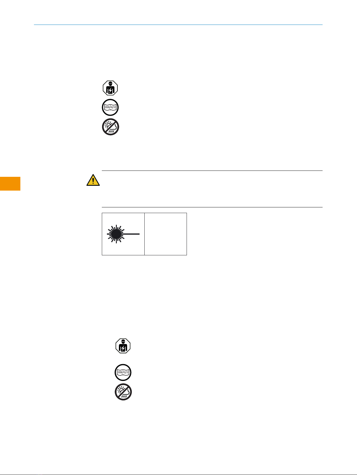
Do not install the product in places exposed to direct UV radiation (sun‐
light) or other weather conditions.
The product must be adequately protected against moisture and contami‐
nation.
Laser notes
CAUTION
Interference, manipulation or incorrect use can lead to hazardous exposure due to laser
radiation.
The emitted light beam must not be focused by means of additional optical devices.
LASER
1
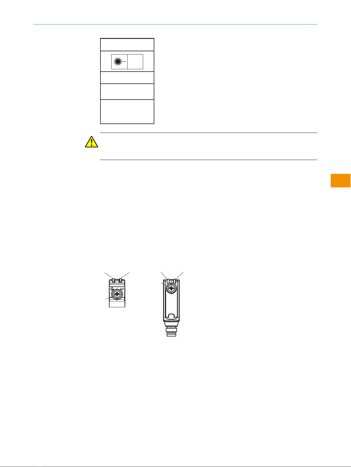
Figure 1: Laser class 1
This device complies with the following standards:
•EN/IEC 60825-1:2014
•21 CFR 1040.10 and 1040.11 except for tolerances according to Laser Notice No.
56 dated May 8, 2019.
The laser is eye-safe.
The laser marking is located on the housing imprint on the sensor.
■Read the operating instructions before commissioning.
■
Connection, mounting, and configuration may only be performed by trained
specialists.
■
2006/42/EC
NO
SAFETY
Not a safety component in accordance with the EU Machinery Directive.
■
Do not install the sensor at locations that are exposed to direct sunlight
or other weather influences, unless this is expressly permitted in the operating
instructions.
■When commissioning, protect the device from moisture and contamination.
■These operating instructions contain information required during the life cycle of
the sensor.
OPERATING INSTRUCTION
6O P E R A T I N G I N S T R U C T I O N | GL6L 8025389.1CGF/2021-07-13 | SICK
Subject to change without notice
en

EN/IEC 60825-1:2014
LASER CLASS 1
Laser
1
Maximum pulse power < 5.95 mW
Puls length: 2 µs
Wavelength: 670 - 690 nm
Complies with FDA performance
standards except for conformance with
IEC 60825-1 Ed. 3,
as described in Laser Notice No. 56,
dated May 8, 2019
ATTENTION
WARNING: Interruption, manipulation or incorrect use can lead to hazardous exposure
due to laser radiation.
2.2 Intended use
The GL6L is an opto-electronic photoelectric retro-reflective sensor (referred to as “sen‐
sor” in the following) for the optical, non-contact detection of objects. A reflector is
required for this product to function. If the product is used for any other purpose or
modified in any way, any warranty claim against SICK AG shall become void.
3 Product description
3.1 Operating and status indicators
GL6L-xxx1x
1
2 3 23
1
1Potentiometer: sensitivity adjustment
2Yellow LED: status of received light beam
3Green LED: Supply voltage active
GL6L-xxx3x
Sensor which it is not possible to set: The sensor is adjusted and ready for operation.
OPERATING INSTRUCTION
8025389.1CGF/2021-07-13 | SICK O P E R A T I N G I N S T R U C T I O N | GL6L 7
Subject to change without notice
en

2 3 23
4 Mounting
Mount the sensor and the reflector using suitable mounting brackets (see the SICK
range of accessories). Align the sensor and reflector with each other.
5 Electrical installation
The sensors must be connected in a voltage-free state (UV = 0V). The following informa‐
tion must be observed depending on the connection type:
– Plug connection: pin assignment
– Cable: wire color
Only apply voltage/switch on the voltage supply (UV >0V) once all electrical connec‐
tions have been established.
Explanation of connection terminology:
BN = Brown
WH = White
BU = Blue
BK = Black
n. c. = no connection
Q = switching output 1
Q = switching output 2
L+ = supply voltage (Uv)
M = common
L.ON = light operate
D.ON = dark operate
OPERATING INSTRUCTION
8O P E R A T I N G I N S T R U C T I O N | GL6L 8025389.1CGF/2021-07-13 | SICK
Subject to change without notice
en

Connection and Output detail:
Table 1: DC
GL6L -P1xxx
-N1xxx
-E2xxx
-F2xxx
-P3xxx
-N3xxx
-P5xxx
-N5xxx
-P4xxx
-N4xxx
-P6xxx
-N6xxx
-P7xxx
-N7xxx
-E4xxx
-F4xxx
-E6xxx
-F6xxx
-E7xxx
-F7xxx
1 = BN + (L+) + (L+) + (L+) + (L+) + (L+)
2 = WH -Q- n. c. Q
3 = BU - (M) - (M) - (M) - (M) - (M)
4 = BK Q Q Q Q Q
0.205 mm2 /
AWG24 0.205 mm2 /
AWG24
4
3 1
4
3
2
1
4
3
2
1
Table 2: Output Operation
GL6L
-Pxxxx = Q output
-Nxxxx = Q output
-Fxxxx = Q + Q output
-Exxxx = Q + Q output
-Px1xx
-Px2xx
-Px5xx
-Px6xx
L.ON, PNP: Q (≤ 100 mA)
+ (L+)
Q
‒ (M)
Load
+ (L+)
Q
‒ (M)
Load
-Px1xx
-Px2xx
-Px3xx
-Px4xx
D.ON, PNP: Q (≤ 100 mA)
+ (L+)
Q
‒ (M)
Load
+ (L+)
Q
‒ (M)
Load
-Nx1xx
-Nx2xx
-Nx5xx
-Nx6xx
L.ON, NPN Open Collector Q (≤ 100 mA)
+ (L+)
Q
‒ (M)
+ (L+)
Q
‒ (M)
Load
+ (L+)
Q
‒ (M)
Load
-Nx1xx
-Nx2xx
-Nx3xx
-Nx4xx
D.ON, NPN Open Collector Q (≤ 100 mA)
+ (L+)
Q
‒ (M)
Load
+ (L+)
Q
‒ (M)
+ (L+)
Q
‒ (M)
Load
OPERATING INSTRUCTION
8025389.1CGF/2021-07-13 | SICK O P E R A T I N G I N S T R U C T I O N | GL6L 9
Subject to change without notice
en

5.1 Notes on UL approval
The device shall be supplied from an isolating transformer having a secondary overcur‐
rent protective device that complies with UL 248 to be installed in the field rated either:
a) max 5 amps for voltages 0 ~ 20 V (0 ~ 28.3 V peak), or
b) 100 / Vp for voltages of 20 ~ 30 V (28.3 ~ 42.4 V peak).
Alternatively, they can be supplied from a Class 2 power supply.
UL Environmental Rating: Enclosure type 1
6 Commissioning
6.1 Alignment
Align the sensor with a suitable reflector. Select the position so that the red emitted
light beam hits the center of the reflector. The sensor must have a clear view of the
reflector, with no object in the path of the beam [see figure 2]. You must ensure that the
optical openings of the sensor and reflector are completely clear.
Figure 2: Alignment
6.2 Sensing range
Adjust the distance between the photoelectric sensor and the reflector according to the
relevant diagram [see figure 3] (x= sensing range, y= operating reserve).
After alignment, place a non-transparent object into the path of the beam. Check the
function as described in table 2. If the switching output fails to behave as described in
table 2, check the application conditions.
OPERATING INSTRUCTION
10 O P E R A T I N G I N S T R U C T I O N | GL6L 8025389.1CGF/2021-07-13 | SICK
Subject to change without notice
en

100
10
1
Operating reserve
Distance in m (feet)
0 2
(6.56)
4
(13.12)
6
(19.69)
8
(26.25)
10
(32.81)
12
(39.37)
21 3
Figure 3: Characteristic line GL6L
1
2
3
Distance in m (feet)
0 2
(6.56)
4
(13.12)
6
(19.69)
8
(26.25)
10
(32.81)
12
(39.37)
0.08 5.54.5
0.08 1210
0.08 86.5
D
A
B
C
Figure 4: Bar graph display
1PL10F
2PL20F
3P250F
ASensing range min. in mm
BSensing range max. in mm
CMaximum distance range from reflector to sensor (operating reserve 1)
DRecommended distance range from reflector to sensor (operating reserve 2)
blue Recommended sensing range for the best performance
6.3 Settings
Sensitivity setting
Sensor which it is not possible to set: The sensor is adjusted and ready for operation.
The sensitivity is adjusted with the potentiometer (type: 5-turn). Clockwise rotation:
operating reserve increased; counterclockwise rotation: operating reserve reduced. We
recommend setting the potentiometer to “Maximum”. A lower operating reserve may be
necessary for depolarizing surfaces.
The sensor is adjusted and ready for operation.
7 Troubleshooting
The Troubleshooting table indicates measures to be taken if the sensor stops working.
Table 3: Troubleshooting
LED/fault pattern Cause Measures
Yellow LED does not light up
even though the light beam
is aligned to the reflector and
there is no object in the path of
the beam
No voltage or voltage below
the limit values
Check the power supply,
check all electrical connec‐
tions (cables and plug connec‐
tions)
Voltage interruptions Ensure there is a stable power
supply without interruptions
Sensor is faulty If the power supply is OK,
replace the sensor
OPERATING INSTRUCTION
8025389.1CGF/2021-07-13 | SICK O P E R A T I N G I N S T R U C T I O N | GL6L 11
Subject to change without notice
en

LED/fault pattern Cause Measures
Yellow LED flashes Sensor is still ready for oper‐
ation, but the operating condi‐
tions are not ideal
Check the operating condi‐
tions: Fully align the beam
of light (light spot) with the
reflector. / Clean the optical
surfaces (sensor and reflec‐
tor) / If the potentiometer is
set to the max. sensitivity:
Reduce the distance between
the sensor and the reflector,
and check the reflector type /
Reflector is not suitable for
the application in question
(we recommend only using
SICK reflectors) / Check sens‐
ing range and adjust if neces‐
sary / Distance between the
sensor and the reflector is too
long
Signal interruptions when
object is detected
Depolarizing property of the
object surface (e.g., tape),
reflection
Reduce sensitivity or change
the position of the sensor
8 Disassembly and disposal
The sensor must be disposed of in line with applicable country-specific regulations.
When disposing of them, you should try to recycle them (especially the precious met‐
als).
NOTE
Disposal of batteries, electric and electronic devices
•According to international directives, batteries, accumulators and electrical or
electronic devices must not be disposed of in general waste.
•The owner is obliged by law to return this devices at the end of their life to the
respective public collection points.
•
WEEE: This symbol on the product, its package or in this document,
indicates that a product is subject to these regulations.
9 Maintenance
This SICK sensor is maintenance-free.
We do, however, recommend that the following activities are undertaken regularly:
•Clean the optical interfaces and housing
•Check the fittings and plug connectors
OPERATING INSTRUCTION
12 O P E R A T I N G I N S T R U C T I O N | GL6L 8025389.1CGF/2021-07-13 | SICK
Subject to change without notice
en

Cleaning
NOTICE
Equipment damage due to improper cleaning.
Improper cleaning may result in equipment damage.
■Only use recommended cleaning agents and tools.
■Never use sharp objects for cleaning.
bClean the optical surfaces at regular intervals and, in the event of contamina‐
tion, with a lint-free lens cloth (part number 4003353) and plastic cleaner (part
number 5600006). The cleaning interval essentially depends on the ambient
conditions.
No modifications may be made to devices.
Subject to change without notice. Specified product properties and technical data are
not written guarantees.
OPERATING INSTRUCTION
8025389.1CGF/2021-07-13 | SICK O P E R A T I N G I N S T R U C T I O N | GL6L 13
Subject to change without notice
en

10 Technical specifications
GL6L
Laser class 1
Laser class 11)
maximum pulse power < 5.95 mW
Pulse duration 2 µs
Wavelength 670 - 690 nm
Sensing range (with reflector P250F) 0.08 m ... 10 m
Sensing range max. (with reflector P250F) 0.08 m ... 12 m
Light spot size / distance 3.5 mm / 1,000 mm
Supply voltage UBDC 10 ... 30 V2)
Output current Imax. 100 mA3)
Switching frequency 1,000 Hz4)
Response time 0.625 ms 5)
Enclosure rating IP67
Protection class III
Circuit protection A, C, D6)
Ambient temperature, operation -20 ... +50 °C7)8)
1) To ensure reliable operation, it is recommended to use fine triple reflectors or reflective tape. Suitable reflectors and tapes can be found in
the SICK accessories range. Use of reflectors with large-scale triple structures can negatively influence functionality.
2) Limit values
Reverse polarity protected UB connections
Residual ripple max. 5Vss
3) As of UB > 24 V, a max. load current Imax. = 50 mA is permitted.
4) With light / dark ratio 1:1
5) Signal transit time with resistive load
6) A = UB-connections reverse polarity protected
C = Interference suppression
D = outputs overcurrent and short-circuit protected
7) As of Ta ≥ 45 °C, a max. supply voltage UB = 24 V and a max. load current Imax. = 50 mA is permitted.
8) Warm-up time @ -20 °C: 3 seconds
OPERATING INSTRUCTION
14 O P E R A T I N G I N S T R U C T I O N | GL6L 8025389.1CGF/2021-07-13 | SICK
Subject to change without notice
en

10.1 Dimensional drawing
6.3
(0.25)
0.5
(0.02)
21
(0.83)
0.5
(0.02)
9.7
(0.38)
3
(0.12)
11.5
(0.45)
31.5 (1.24)
28.5 (1.12)
25.4 (1.00)
2.3
(0.09)
18.3
(0.72)
305 (12.01)
9.7
(0.38)
12
(0.47)
1
2
4
4
3
Figure 5: Dimensional drawing
1Center of optical axis, sender
2Center of optical axis, receiver
3Operating and status indicators
4M3 threaded mounting hole
10.2 Light spot diagram
Sensor
Ø 28
(1.10)
Ø 3.5
(0.14)
Ø 58
(2.28)
Ø 70
(2.76)
1
(3.28)
5
(16.40)
10
(32.81)
12
(39.37)
Distance in m (feet)
Diameter in mm (inch)
11 Annex
11.1 Conformities and certificates
You can obtain declarations of conformity, certificates, and the current operating
instructions for the product at www.sick.com. To do so, enter the product part number
in the search field (part number: see the entry in the “P/N” or “Ident. no.” field on the
type label).
OPERATING INSTRUCTION
8025389.1CGF/2021-07-13 | SICK O P E R A T I N G I N S T R U C T I O N | GL6L 15
Subject to change without notice
en

Beschriebenes Produkt
G6L
GL6L
Hersteller
SICK AG
Erwin-Sick-Str. 1
79183 Waldkirch
Deutschland
Fertigungsstandort
SICK Malaysia
Rechtliche Hinweise
Dieses Werk ist urheberrechtlich geschützt. Die dadurch begründeten Rechte bleiben
bei der Firma SICK AG. Die Vervielfältigung des Werks oder von Teilen dieses Werks
ist nur in den Grenzen der gesetzlichen Bestimmungen des Urheberrechtsgesetzes
zulässig. Jede Änderung, Kürzung oder Übersetzung des Werks ohne ausdrückliche
schriftliche Zustimmung der Firma SICK AG ist untersagt.
Die in diesem Dokument genannten Marken sind Eigentum ihrer jeweiligen Inhaber.
© SICK AG. Alle Rechte vorbehalten.
Originaldokument
Dieses Dokument ist ein Originaldokument der SICK AG.
Laser
1
2006/42/EC
NO
SAFETY
BETRIEBSANLEITUNG
8025389.1CGF/2021-07-13 | SICK B E T R I E B S A N L E I T U N G | GL6L 17
Irrtümer und Änderungen vorbehalten
de

Inhalt
1 Zu diesem Dokument.............................................................. 19
2 Zu Ihrer Sicherheit................................................................... 20
3 Produktbeschreibung.............................................................. 21
4 Montage................................................................................... 22
5 Elektrische Installation............................................................ 22
6 Inbetriebnahme....................................................................... 24
7 Störungsbehebung.................................................................. 25
8 Demontage und Entsorgung................................................... 26
9 Wartung.................................................................................... 27
10 Technische Daten.................................................................... 28
11 Anhang..................................................................................... 29
BETRIEBSANLEITUNG
18 B E T R I E B S A N L E I T U N G | GL6L 8025389.1CGF/2021-07-13 | SICK
Irrtümer und Änderungen vorbehalten
de

1 Zu diesem Dokument
1.1 Weiterführende Informationen
Die Produktseite mit weiterführenden Informationen finden Sie unter der SICK ProductID
unter: pid.sick.com/{P/N}.
P/N entspricht der Artikelnummer des Produkts.
Folgende Informationen sind produktabhängig verfügbar:
•Datenblätter
•Dieses Dokument in allen verfügbaren Sprachversionen
•CAD-Daten und Maßzeichnungen
•Zertifikate (z.B. Konformitätserklärung)
•Weitere Publikationen
•Software
•Zubehör
1.2 Symbole und Dokumentkonventionen
Warnhinweise und andere Hinweise
GEFAHR
Weist auf eine unmittelbar gefährliche Situation hin, die zum Tod oder zu schweren
Verletzungen führt, wenn sie nicht vermieden wird.
WARNUNG
Weist auf eine möglicherweise gefährliche Situation hin, die zum Tod oder zu schweren
Verletzungen führen kann, wenn sie nicht vermieden wird.
VORSICHT
Weist auf eine möglicherweise gefährliche Situation hin, die zu mittelschweren oder
leichten Verletzungen führen kann, wenn sie nicht vermieden wird.
WICHTIG
Weist auf eine möglicherweise gefährliche Situation hin, die zu Sachschäden führen
kann, wenn sie nicht vermieden wird.
HINWEIS
Hebt nützliche Tipps und Empfehlungen sowie Informationen für einen effizienten und
störungsfreien Betrieb hervor.
Handlungsanleitung
bDer Pfeil kennzeichnet eine Handlungsanleitung.
1. Eine Abfolge von Handlungsanleitungen ist nummeriert.
2. Nummerierte Handlungsanleitungen in der gegebenen Reihenfolge befolgen.
✓Der Haken kennzeichnet ein Ergebnis einer Handlungsanleitung.
BETRIEBSANLEITUNG
8025389.1CGF/2021-07-13 | SICK B E T R I E B S A N L E I T U N G | GL6L 19
Irrtümer und Änderungen vorbehalten
de

2 Zu Ihrer Sicherheit
2.1 Allgemeine Sicherheitshinweise
Der Anschluss, die Montage und die Konfiguration des Produkts dürfen
nur von geschultem Fachpersonal vorgenommen werden.
2006/42/EC
NO
SAFETY
Bei diesem Produkt handelt es sich um kein sicherheitsgerichtetes Bauteil
im Sinne der EU-Maschinenrichtlinie.
Installieren Sie das Produkt nicht an Orten, die direkter UV-Strahlung
(Sonnenlicht) oder sonstigen Wettereinflüssen ausgesetzt sind.
Das Produkt ist ausreichend vor Feuchtigkeit und Verschmutzung zu
schützen.
Laserhinweise
VORSICHT
Eingriffe, Manipulation oder eine unsachgemäße Verwendung kann zu gefährlicher
Exposition gegenüber Laserstrahlung führen.
Die emittierte Lichtstrahlung darf nicht mithilfe zusätzlicher optischer Geräte fokussiert
werden.
LASER
1
Abbildung 1: Laserklasse 1
Dieses Gerät entspricht folgenden Normen:
•EN/IEC 60825-1:2014
•21 CFR 1040.10 und 1040.11 mit Ausnahme von Abweichungen nach Laserhin‐
weis No. 56 vom 08.05.2019.
Der Laser ist augensicher.
Die Laserkennzeichnung befindet sich auf dem Gehäuseaufdruck auf dem Sensor.
■Lesen Sie vor der Inbetriebnahme des Geräts die Betriebsanleitung.
■
Der Anschluss, die Montage und die Konfiguration des Geräts dürfen nur
von geschultem Fachpersonal vorgenommen werden.
■
2006/42/EC
NO
SAFETY
Bei diesem Gerät handelt es sich um kein Sicherheitsbauteil im Sinne der
EU-Maschinenrichtlinie.
■
Installieren Sie den Sensor nicht an Orten, die direkter Sonneneinstrahlung
oder sonstigen Wettereinflüssen ausgesetzt sind, außer dies ist in der Betriebsan‐
leitung ausdrücklich erlaubt.
BETRIEBSANLEITUNG
20 B E T R I E B S A N L E I T U N G | GL6L 8025389.1CGF/2021-07-13 | SICK
Irrtümer und Änderungen vorbehalten
de
Table of contents
Languages:
Other SICK Accessories manuals

SICK
SICK GSE2 Flat Side User manual

SICK
SICK GSE6L Series User manual

SICK
SICK GTE6 Series User manual

SICK
SICK WTB4F User manual

SICK
SICK NAV350 User manual

SICK
SICK OD2000 User manual

SICK
SICK WL100-2 User manual

SICK
SICK deTec4 Core User manual

SICK
SICK LMS5 Series User manual

SICK
SICK MRS1000 User manual