SICK WT18-3 User manual

OPERATING INSTRUCTION
WT(F)18-3
Compact photoelectric sensors
en / de / fr / it / pt / es / zh / ja / ru
SICK AG, Erwin-Sick-Strasse 1, D-79183 Waldkirch
8010586.YM42

Photoelectric proximity sensor
Operating instructions
1 Safety notes
■Read the operating instructions before commissioning.
■Connection, mounting, and setting may only be performed by trained specialists.
■Not a safety component in accordance with the EU Machinery Directive.
■UL: Only for use in applications in accordance with NFPA 79. These devices shall
be protected by a 1 A fuse suitable for 30 V DC. Adapters listed by UL with connec‐
tion cables are available. Enclosure type 1
■When commissioning, protect the device from moisture and contamination.
■These operating instructions contain information required during the life cycle of
the sensor.
2 Correct use
The WT(F)18-3 is an opto-electronic photoelectric proximity sensor (referred to as "sen‐
sor" in the following) for the optical, non-contact detection of objects, animals, and per‐
sons. If the product is used for any other purpose or modified in any way, any warranty
claim against SICK AG shall become void.
WT18-3: Photoelectric proximity sensor with background suppression /
Image: A
3 Commissioning
1 Check the application conditions: Adjust the sensing range and distance to the ob‐
ject or background and the remission capability of the object according to the cor‐
responding diagram [H] (x = sensing range, y = transition range between the set
sensing range and suppression of the background as a % of the sensing range (ob‐
ject remission / background remission). Remission: 6% = black , 18% = grey ,
90% = white (referring to standard white as per DIN 5033).
The minimum distance (= y) for background suppression can be determined from
diagram [H] as follows:
Example: x = 300 mm, y = 7 => 7 % of 300 mm = 21 mm. That is, the background
is suppressed at a distance of > 321mm from the sensor.
8010586.YM42 | SICK
Subject to change without notice 1

2 Mount the sensor using a suitable mounting bracket (see the SICK range of acces‐
sories).
Note the sensor's maximum permissible tightening torque of 1.3 Nm.
Note the preferred direction of the object relative to the sensor [see A].
3 The sensors must be connected in a voltage-free state (Uv = 0 V). The information
in the graphics [B] must be observed, depending on the connection type:
– Male connector connection: pin assignment
– Cable: core color
Only apply voltage/switch on the power supply (Uv > 0 V) once all electrical connec‐
tions have been established. The green LED indicator lights up on the sensor.
Explanations of the connection diagram (Graphic B):
Switching outputs Q and /Q (according to Graphic B):
WT(F)18-3P/K/V (PNP: load -> M)
WT(F)18-3N (NPN: load -> L+)
Alarm/health = diagnostic output (see Additional functions)
4 WT18-3Xx3x / -3Xx8x: Align the sensor with the object. Select the position so that
the red emitted light beam hits the center of the object. You must ensure that the
optical opening (front screen) of the sensor is completely clear [E]. We recommend
making the adjustments using an object with a low remission.
WT18-3Xx1x / -3Xx7x: Align the sensor with the object. Select the position so that
the infrared light (not visible) hits the center of the object. The correct alignment
can only be detected via the LED indicators. Please refer to Graphics C and E. You
must ensure that the optical opening (front screen) of the sensor is completely
clear. We recommend making the adjustments using an object with a low remissi‐
on.
3 COMMISSIONING
28010586.YM42 | SICK
Subject to change without notice
0
5
10
15
6%/90%
18%/90%
90%/90%
Distance in mm (inch)
mm
(inch)
100
(3.94)
200
(7.87)
300
(11.81)
400
(15.75)
500
(19.69)
600
(23.62)
700
(27.56)
1
2
3
Image H: WT18-3Xx3x /
-3Xx8x
6%/90%
90%/90%
18%/90%
0
5
10
15
Distance in mm (inch)
mm
(inch)
100
(3.94)
200
(7.87)
300
(11.81)
400
(15.75)
500
(19.69)
600
(23.62)
700
(27.56)
1
2
3
Image:H-2: WT18-3Xx1x / -3Xx7x
0
5
10
15
18%/90%
90%/90%
6%/90%
Distance in mm (inch)
mm
(inch)
200
(7.87)
400
(15.75)
600
(23.62)
800
(31.50)
1000
(39.37)
1
2
3
Image H-3: -WT18-3Xx2x Image H-4: WTF18-3Vx1x
Technical data and connection diagrams (figure B) starting on page 69.

Image: E
5
Sensor with potentiometer:
WT18-3Xxx0: The sensing range is adjusted with the potentiometer (type: 4 rotati‐
ons). Clockwise rotation: sensing range increased; counterclockwise rotation: sen‐
sing range reduced. We recommend placing the switching state in the object, e. g.,
see graphic F. Once the sensing range has been adjusted, the object is removed
from the path of the beam, which causes the background to be suppressed and
the switching output to change (see graphic C).
WT18-3Xxx1: Sensor with teach-in button:
The sensing range is adjusted by pressing the teach-in button. Do not operate the
teach-in button using sharp objects. We recommend placing the switching state in
the object, e. g., see graphic F. Once the sensing range has been adjusted, the ob‐
ject is removed from the path of the beam, which causes the background to be
suppressed and the switching output to change (see graphic C).
The sensor is adjusted and ready for operation. Refer to graphics C and G to check
the function. If the switching output fails to behave in accordance with graphic C,
check application conditions. See section Fault diagnosis.
COMMISSIONING 3
8010586.YM42 | SICK
Subject to change without notice 3

Image: C
Image: G
Teach-in mode
for objects /
Teach-in mode
for objects
Teach-in time /
Teach-in time
Alignment /
Alignment
LED indicator /
LED indicator
Results /
Results
Double teach-in
pushbutton:
Press both push‐
buttons simultan‐
eously /
Double teach-in
pushbutton:
Press both push‐
buttons simultan‐
eously
> 2 s Sensor to ob‐
ject /
Sensor to object
Sensing range is
adjusted accor‐
ding to object /
Sensing range is
adjusted accor‐
ding to object
Double teach-in
pushbutton: "+" /
Double teach-in
pushbutton: "+"
Approx. 0.5 s /
Approx. 0.5 s
Sensor to ob‐
ject /
Sensor to object
Sensing range is
increased /
Sensing range is
increased
Double teach-in
pushbutton: "-“" /
Double teach-in
pushbutton: "-“"
Approx. 0.5 s /
Approx. 0.5 s
Sensor to ob‐
ject /
Sensor to object
Sensing range is
reduced /
Sensing range is
reduced
4
48010586.YM42 | SICK
Subject to change without notice

5 Additional functions
Alarm output: WTF18-3Vxxx sensors feature a pre-failure notification output (“Alarm” in
connection diagram [B]), which issues a notification if the sensor is only ready for ope‐
ration to a limited extent. Possible causes: Sensor is contaminated, sensor is out of
alignment. In the good state: LOW (UV < V); if excessively contaminated: HIGH (>+UV- V).
The LED indicator flashes in this case.
Health output: WT18-3P420S22, WT18-3P420S32 sensors feature a pre-failure notifi‐
cation output ("Health" in connection diagram [B]), which issues a notification if the
sensor is only ready for operation to a limited extent or the cable has been interrupted.
Possible causes: Sensors are contaminated, sensors are out of alignment, cable is da‐
maged. In the good state: HIGH (>+UV- V); if excessively contaminated or in the event of
cable interruption: LOW (UV < V). The LED indicator flashes in this case.
6 Devices with special features
WT18-3A600S02: sensing range is preset: see data sheet, switching frequency:
1000Hz , pin assignment: pin 1 = L+, pin 2 = M, Pin 3 = not connected, Pin 4 = not
connected, Pin 5 = push-pull-output (PNP: Q, NPN: Q/), Pin 6 = not connected
WT18-3N110S03: Connection of 1,200 mm cable and AMP male connector (brown: L+,
blue: M, black: Q, white: Q/), potentiometer for setting is sealed, sensing range is pre‐
set: see data sheet
WT18-3P120S06: sensing range: 850 mm / 90%, switching frequency: 400 Hz
WT18-3P411S07, WT18-3P430S40: Sensing range is preset, see data sheet
WT18-3P420S09 / WT18-3P420S12: sensing range: 50 to 700 mm / 90%
WT18-3P420S10: switching frequency: 1,500 Hz
WT18-3P420S05 / WT18-3P421S36: sensing range: 50 to 850 mm / 6%, switching
frequency: 400 Hz
WT18-3P430S19: sensing range: 50 to 500 mm / 6%, switching frequency: 350 Hz
WT18-3P120S20, WT18-3P420S25: Sensing range 50 … 850 mm / 6%, switching fre‐
quency 200 Hz
WT18-3P420S21: Sensing range 50 … 400 mm / 90%, switching frequency 1,500 Hz
WT18-3P420S22: pin assignment: pin 1 = L+, pin 2 = Health, pin 3 = M, pin 4 = Q
(light switching)
WT18-3P430S29, WT18-3P610S30: For extreme shock loads
WT18-3P420S31: Sensing range is preset, see data sheet. Detection of objects has be‐
come very restricted in the range 0 ... 20 mm
WT18-3P420S32: sensing range is pre-set: 1,000 mm / 90%, without potentiometer,
pin assignment: pin 1 = L+, pin 2 = Health, pin 3 = M, pin 4 = Q (light switching)
WT18-3P930S34: Sensing range 50 … 60 mm / 90%, switching frequency 300 Hz
WT18-3P020S35: 2,000 mm cable with M8 male connector, 4-pin, pin 1: L+, pin 2: Q/,
pin 3: M, pin 4: Q
WT18-3P421S36: Sensing range 50 … 850 mm / 6%, switching frequency 400 Hz
WT18-3P010S37: 100 mm cable with M12 male connector, 4-pin, pin 1: L+, pin 2: Q/,
pin 3: M, pin 4: Q
ADDITIONAL FUNCTIONS 5
8010586.YM42 | SICK
Subject to change without notice 5

WT18-3P931S38: Sensing range 800 mm / 6%, switching frequency 200 Hz, response
time ≥ 2.5 ms, 100 mm cable with M12 male connector, 4-pin
WT18-3P430S40: Sensing range is preset: see data sheet
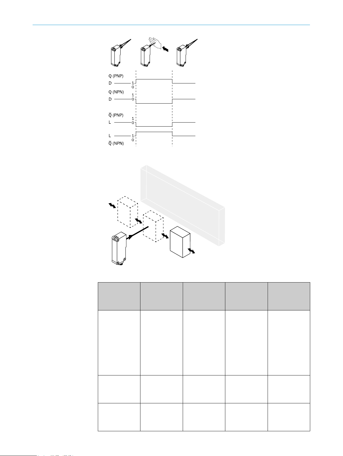
WT18-3A600S02: Sensing range 100 mm / 90%, switching frequency 1,000 Hz, swit‐
ching output: push/pull output Q: PNP: light switching; NPN: dark switching, pin 1: L+,
pin 2: M, pin 3: not connected, pin 4: not connected, pin 5: Q, pin 6: not connected
7 Fault diagnosis
Table Fault diagnosis indicates which measures are to be taken if the sensor stops
working.
8 Table Fault diagnosis
LED indicator/fault pattern /
LED indicator/fault pattern
Cause /
Cause
Measures /
Measures
Green LED does not light up /
Green LED does not light up
No voltage or voltage below
the limit values /
No voltage or voltage below
the limit values
Check the power supply,
check all electrical connecti‐
ons (cables and plug connecti‐
ons) /
Check the power supply,
check all electrical connecti‐
ons (cables and plug connecti‐
ons)
Green LED does not light up /
Green LED does not light up
Voltage interruptions /
Voltage interruptions
Ensure there is a stable power
supply without interruptions /
Ensure there is a stable power
supply without interruptions
Green LED does not light up /
Green LED does not light up
Sensor is faulty /
Sensor is faulty
If the power supply is OK, re‐
place the sensor /
If the power supply is OK, re‐
place the sensor
Yellow LED flashes; if Health is
present then take note of the
corresponding output signal; if
Alarm is present then take note
of the corresponding output
signal /
Yellow LED flashes; if Health is
present then take note of the
corresponding output signal; if
Alarm is present then take note
of the corresponding output
signal
Sensor is still ready for opera‐
tion, but the operating conditi‐
ons are not ideal/additionally
with health output: power sup‐
ply interrupted /
Sensor is still ready for opera‐
tion, but the operating conditi‐
ons are not ideal/additionally
with health output: power sup‐
ply interrupted
Check the operating conditi‐
ons: Fully align the beam of
light (light spot) with the ob‐
ject. / Clean the optical surfa‐
ces . / Readjust the sensitivity
(potentiometer) (teach-in) /
Check sensing range and ad‐
just if necessary; see graphic
F. / With health output: Check
the power supply, check all
electrical connections (cables
and plug connections). /
Check the operating conditi‐
ons: Fully align the beam of
light (light spot) with the ob‐
ject. / Clean the optical surfa‐
ces . / Readjust the sensitivity
(potentiometer) (teach-in) /
Check sensing range and ad‐
just if necessary; see graphic
F. / With health output: Check
the power supply, check all
electrical connections (cables
and plug connections).
7 FAULT DIAGNOSIS
68010586.YM42 | SICK
Subject to change without notice

LED indicator/fault pattern /
LED indicator/fault pattern
Cause /
Cause
Measures /
Measures
Yellow LED flashes (only brie‐
fly) /
Yellow LED flashes (only briefly)
Teach-in mode /
Teach-in mode
Check the teach-in mode /
Check the teach-in mode
Yellow LED lights up, no object
in the path of the beam /
Yellow LED lights up, no object
in the path of the beam
/ Distance between the sen‐
sor and the background is too
short /
/ Distance between the sen‐
sor and the background is too
short
Reduce the sensing range,
see graphic F /
Reduce the sensing range,
see graphic F
Object is in the path of the be‐
am, yellow LED does not light
up /
Object is in the path of the be‐
am, yellow LED does not light
up
Distance between the sensor
and the object is too long or
sensing range is set too
short /
Distance between the sensor
and the object is too long or
sensing range is set too short
Increase the sensing range,
see graphic F /
Increase the sensing range,
see graphic F
9 Disassembly and disposal
The sensor must be disposed of according to the applicable country-specific regulati‐
ons. Efforts should be made during the disposal process to recycle the constituent ma‐
terials (particularly precious metals).
10 Maintenance
SICK sensors are maintenance-free.
We recommend doing the following regularly:
•Clean the external lens surfaces
•Check the screw connections and plug-in connections
No modifications may be made to devices.
Subject to change without notice. Specified product properties and technical data are
not written guarantees.
DISASSEMBLY AND DISPOSAL 9
8010586.YM42 | SICK
Subject to change without notice 7

Reflexions-Lichttaster
Betriebsanleitung
11 Sicherheitshinweise
■Vor der Inbetriebnahme die Betriebsanleitung lesen.
■Anschluss, Montage und Einstellung nur durch Fachpersonal.
■Kein Sicherheitsbauteil gemäß EU-Maschinenrichtlinie.
■UL: Nur zur Verwendung in Anwendungen gemäß NFPA 79. Diese Geräte müssen
mit einer für 30V DC geeigneten 1A-Sicherung abgesichert werden. Von UL geliste‐
te Adapter mit Anschlusskabeln sind verfügbar. Enclosure type 1
■Gerät bei Inbetriebnahme vor Feuchte und Verunreinigung schützen.
■Diese Betriebsanleitung enthält Informationen, die während des Lebenszyklus des
Sensors notwendig sind.
12 Bestimmungsgemäße Verwendung
Die WT(F)18-3 ist ein optoelektronischer Reflexions-Lichttaster (im Folgenden Sensor
genannt) und wird zum optischen, berührungslosen Erfassen von Sachen, Tieren und
Personen eingesetzt. Bei jeder anderen Verwendung und bei Veränderungen am Pro‐
dukt verfällt jeglicher Gewährleistungsanspruch gegenüber der SICK AG.
WT18-3: Reflexionslichttaster mit Hintergrundausblendung /
Abb.: A
88010586.YM42 | SICK
Subject to change without notice

13 Inbetriebnahme
1 Einsatzbedingungen prüfen: Schaltabstand und Distanz zum Objekt bzw. Hinter‐
grund sowie Remissionsvermögen des Objektes mit dem zugehörigen Diagramm
[vgl. H] abgleichen (x = Schaltabstand, y = Übergangsbereich zwischen eingestell‐
tem Schaltabstand und Ausblendung des Hintergrundes in % des Schaltabstands
(Remission Objekt / Remission Hintergrund)). Remission: 6 % = schwarz , 18 % =
grau , 90 % = weiß (bezogen auf Standardweiß nach DIN 5033).
Die minimale Distanz (= y) für die Hintergrundausblendung kann aus dem Dia‐
gramm [vgl. H] wie folgt ermittelt werden:
Beispiel: x = 300 mm, y = 7 => 7 % von 300 mm = 21 mm. D. h. der Hintergrund
wird ab einer Distanz von > 321 mm vom Sensor ausgeblendet.
2 Den Sensor an einen geeigneten Befestigungswinkel montieren (siehe SICK-Zube‐
hör-Programm).
Maximal zulässiges Anzugsdrehmoment des Sensors von 1.3 Nm beachten.
Vorzugsrichtung des Objektes zum Sensor beachten [vgl. A].
3 Anschluss der Sensoren muss spannungsfrei (UV = 0 V) erfolgen. Je nach An‐
schlussart sind die Informationen in den Grafiken [vgl. B] zu beachten:
– Steckeranschluss: Pinbelegung
– Leitung: Adernfarbe
Erst nach Anschluss aller elektrischen Verbindungen die Spannungsversorgung (UV
> 0 V) anlegen bzw. einschalten. Am Sensor leuchtet die grüne Anzeige-LED.
Erläuterungen zum Anschlussschema (Grafik B):
Schaltausgänge Q bzw. /Q (gemäß Grafik B):
WT(F)18-3P / K / V (PNP: Last -> M)
WT(F)18-3N (NPN: Last -> L+)
Alarm / Health = Diagnoseausgang (siehe Zusatzfunktionen)
INBETRIEBNAHME 13
8010586.YM42 | SICK
Subject to change without notice 9
0
5
10
15
6%/90%
18%/90%
90%/90%
Distance in mm (inch)
mm
(inch)
100
(3.94)
200
(7.87)
300
(11.81)
400
(15.75)
500
(19.69)
600
(23.62)
700
(27.56)
1
2
3
Image H: WT18-3Xx3x /
-3Xx8x
6%/90%
90%/90%
18%/90%
0
5
10
15
Distance in mm (inch)
mm
(inch)
100
(3.94)
200
(7.87)
300
(11.81)
400
(15.75)
500
(19.69)
600
(23.62)
700
(27.56)
1
2
3
Image:H-2: WT18-3Xx1x / -3Xx7x
0
5
10
15
18%/90%
90%/90%
6%/90%
Distance in mm (inch)
mm
(inch)
200
(7.87)
400
(15.75)
600
(23.62)
800
(31.50)
1000
(39.37)
1
2
3
Image H-3: -WT18-3Xx2x Image H-4: WTF18-3Vx1x
Technische Daten und Anschlussschemata (Grafik B) ab Seite 69.

4 WT18-3Xx3x / -3Xx8x: Sensor auf Objekt ausrichten. Positionierung so wählen,
dass der rote Sendelichtstrahl in der Mitte des Objekts auftrifft. Es ist darauf zu
achten, dass die optische Öffnung (Frontscheibe) des Sensors vollständig frei ist
[vgl. E]. Wir empfehlen, die Einstellung mit einem Objekt von niedriger Remission
vorzunehmen.
WT18-3Xx1x / -3Xx7x: Sensor auf Objekt ausrichten. Positionierung so wählen,
dass das Infrarotlicht (nicht sichtbar) in der Mitte des Objekts auftrifft. Die korrekte
Ausrichtung kann nur über die Anzeige-LEDs erkannt werden. Siehe dazu Grafiken
C und E. Es ist darauf zu achten, dass die optische Öffnung (Frontscheibe) des
Sensors vollständig frei ist. Wir empfehlen, die Einstellung mit einem Objekt von
niedriger Remission vorzunehmen.
Abb.: E
5
Sensor mit Potentiometer:
WT18-3Xxx0: Mit dem Potentiometer (Art: 4 Umdrehungen) wird der Schaltabstand
eingestellt. Drehung nach rechts: Erhöhung des Schaltabstandes, Drehung nach
links: Verringerung des Schaltabstandes. Wir empfehlen, den Schaltabstand in das
Objekt zu legen, z. B. siehe Grafik F. Nachdem der Schaltabstand eingestellt wor‐
den ist, das Objekt aus dem Strahlengang entfernen, der Hintergrund wird dabei
ausgeblendet und der Schaltausgang ändert sich (siehe Grafik C).
WT18-3Xxx1: Sensor mit Teach-in-Taste:
Durch Drücken der Teach-in-Taste wird der Schaltabstand eingestellt. Teach-in-Tas‐
te nicht mit spitzen Gegenständen betätigen. Wir empfehlen, den Schaltabstand in
das Objekt zu legen, z. B. siehe Grafik F. Nach dem der Schaltabstand eingestellt
worden ist, das Objekt aus dem Strahlengang entfernen, der Hintergrund wird da‐
bei ausgeblendet und der Schaltausgang ändert sich (siehe Grafik C).
Sensor ist eingestellt und betriebsbereit. Zur Überprüfung der Funktion Grafik C
und G heranziehen. Verhält sich der Schaltausgang nicht gemäß Grafik C, Einsatz‐
bedingungen prüfen. Siehe Abschnitt Fehlerdiagnose.
13 INBETRIEBNAHME
10 8010586.YM42 | SICK
Subject to change without notice

Abb.: C
Abb.: G
Teach-in-Modus
für Objekte /
Teach-in mode
for objects
Teach-in-Zeit /
Teach-in time
Ausrichtung /
Alignment
Anzeige-LED /
LED indicator
Ergebnis /
Results
Doppel-Teach-in-
Taste: beide Tas‐
ten gleichzeitig
drücken /
Double teach-in
pushbutton:
Press both push‐
buttons simultan‐
eously
> 2 s Sensor auf Ob‐
jekt /
Sensor to object
Schaltabstand
wird auf Objekt
eingestellt /
Sensing range is
adjusted accor‐
ding to object
Doppel-Teach-in-
Taste: „+“ /
Double teach-in
pushbutton: "+"
ca. 0,5 s /
Approx. 0.5 s
Sensor auf Ob‐
jekt /
Sensor to object
Schaltabstand
wird erhöht /
Sensing range is
increased
Doppel-Teach-in-
Taste: „-“ /
Double teach-in
pushbutton: "-“"
ca. 0,5 s /
Approx. 0.5 s
Sensor auf Ob‐
jekt /
Sensor to object
Schaltabstand
wird verringert /
Sensing range is
reduced
14
8010586.YM42 | SICK
Subject to change without notice 11

15 Zusatzfunktionen
Alarmausgang: Die Sensoren WTF18-3Vxxx verfügen über einen Vorausfallmeldeaus‐
gang ("Alarm" im Anschlussschema [B]) der meldet, wenn der Sensor nur noch einge‐
schränkt betriebsbereit ist. Mögliche Ursachen: Verschmutzung des Sensors, Sensor ist
dejustiert. Im Gutzustand: LOW (UV < V), bei zu starker Verschmutzung HIGH (>+UV- V).
Dabei blinkt die Anzeige-LED.
Health-Ausgang: Die Sensoren WT18-3P420S22, WT18-3P420S32 verfügen über ei‐
nen Vorausfallmeldeausgang ("Health" im Anschlussschema [B]), der meldet, wenn der
Sensor nur noch eingeschränkt betriebsbereit ist oder die Leitung unterbrochen ist.
Mögliche Ursachen: Verschmutzung der Sensoren, Sensoren sind dejustiert, Leitung ist
beschädigt. Im Gutzustand: HIGH (>+UV- V), bei zu starker Verschmutzung oder Lei‐
tungsunterbrechung LOW (UV < V). Dabei blinkt die Anzeige-LED.
16 Geräte mit besonderen Merkmalen
WT18-3A600S02: Schaltabstand ist voreingestellt: siehe Datenblatt, Schaltfrequenz
1000Hz , Pinbelegung Pin 1 = L+, Pin 2 = M, Pin 3 = not connected, Pin 4 = not con‐
nected, Pin 5 = push-pull-output (PNP: Q, NPN: Q/), Pin 6 = not connected
WT18-3N110S03: Anschluss 1200 mm Leitung mit AMP-Stecker (braun: L+, blau: M,
schwarz: Q, weiß: Q/), Potentiometer zur Einstellung ist versiegelt, Schaltabstand ist
voreingestellt: siehe Datenblatt
WT18-3P120S06: Schaltabstand: 850 mm / 90 %, Schaltfrequenz 400Hz
WT18-3P411S07, WT18-3P430S40: Schaltabstand ist voreingestellt, siehe Datenblatt
WT18-3P420S09 / WT18-3P420S12: Schaltabstand 50 … 700 mm / 90 %
WT18-3P420S10: Schaltfrequenz 1500 Hz
WT18-3P420S05 / WT18-3P421S36: Schaltabstand 50 … 850 mm / 6 %, Schaltfre‐
quenz 400 Hz
WT18-3P430S19: Schaltabstand 50 … 500 mm / 6 %, Schaltfrequenz 350 Hz
WT18-3P120S20, WT18-3P420S25: Schaltabstand 50 … 850 mm / 6 %, Schaltfre‐
quenz 200 Hz
WT18-3P420S21: Schaltabstand 50 … 400 mm / 90 %, Schaltfrequenz 1500 Hz
WT18-3P420S22: Pinbelegung Pin 1 = L+, Pin 2 = Health, Pin 3 = M, Pin 4 = Q (hell‐
schaltend)
WT18-3P430S29, WT18-3P610S30: für Extremschockbelastungen
WT18-3P420S31: Schaltabstand ist voreingestellt, siehe Datenblatt. Die Detektion von
Objekten ist im Bereich 0 ... 20 mm stark eingeschränkt worden
WT18-3P420S32: Schaltabstand ist voreingestellt: 1000 mm / 90 %, ohne Potentio‐
meter, Pinbelegung Pin 1 = L+, Pin 2 = Health, Pin 3 = M, Pin 4 = Q (hellschaltend)
WT18-3P930S34: Schaltabstand 50 … 60 mm / 90 %, Schaltfrequenz 300 Hz
WT18-3P020S35: 2000 mm Leitung mit M8-Stecker, 4-polig, Pin 1: L+, Pin 2: Q/, Pin
3: M, Pin 4: Q
WT18-3P421S36: Schaltabstand 50 … 850 mm / 6 %, Schaltfrequenz 400 Hz
WT18-3P010S37: 100 mm Leitung mit M12-Stecker, 4-polig, Pin 1: L+, Pin 2: Q/, Pin
3: M, Pin 4: Q
15 ZUSATZFUNKTIONEN
12 8010586.YM42 | SICK
Subject to change without notice

WT18-3P931S38: Schaltabstand 800 mm / 6 %, Schaltfrequenz 200 Hz, Ansprechzeit
≥ 2,5 ms, 100 mm Leitung mit M12-Stecker, 4-polig
WT18-3P430S40: Schaltabstand ist voreingestellt: siehe Datenblatt
WT18-3A600S02: Schaltabstand 100 mm / 90%, Schaltfrequenz 1000 Hz, Schaltaus‐
gang: Push-Pull-Ausgang Q: PNP: hellschaltend; NPN: dunkelschaltend, Pin 1: L+, Pin 2:
M, Pin 3: not connected, Pin 4: not connected, Pin 5: Q, Pin 6: not connected
17 Fehlerdiagnose
Tabelle Fehlerdiagnose zeigt, welche Maßnahmen durchzuführen sind, wenn die
Funktion des Sensors nicht mehr gegeben ist.
18 Tabelle Fehlerdiagnose
Anzeige-LED / Fehlerbild /
LED indicator/fault pattern
Ursache /
Cause
Maßnahme /
Measures
grüne LED leuchtet nicht /
Green LED does not light up
keine Spannung oder Span‐
nung unterhalb der Grenzwer‐
te /
No voltage or voltage below
the limit values
Spannungsversorgung prüfen,
den gesamten elektrischen
Anschluss prüfen (Leitungen
und Steckerverbindungen) /
Check the power supply,
check all electrical connecti‐
ons (cables and plug connecti‐
ons)
grüne LED leuchtet nicht /
Green LED does not light up
Spannungsunterbrechungen /
Voltage interruptions
Sicherstellen einer stabilen
Spannungsversorgung ohne
Unterbrechungen /
Ensure there is a stable power
supply without interruptions
grüne LED leuchtet nicht /
Green LED does not light up
Sensor ist defekt /
Sensor is faulty
Wenn Spannungsversorgung
in Ordnung ist, dann Sensor
austauschen /
If the power supply is OK, re‐
place the sensor
gelbe LED blinkt, wenn Health
vorhanden dann entsprechen‐
des Ausgangssignal beachten,
wenn Alarm vorhanden dann
entsprechendes Ausgangssig‐
nal beachten /
Yellow LED flashes; if Health is
present then take note of the
corresponding output signal; if
Alarm is present then take note
of the corresponding output
signal
Sensor ist noch betriebsbe‐
reit, aber die Betriebsbedin‐
gungen sind nicht optimal /
zusätzlich bei Health-Ausgang:
Spannungsversorgung ist un‐
terbrochen /
Sensor is still ready for opera‐
tion, but the operating conditi‐
ons are not ideal/additionally
with health output: power sup‐
ply interrupted
Betriebsbedingungen prüfen:
Lichtstrahl (Lichtfleck) voll‐
ständig auf das Objekt aus‐
richten / Reinigung der opti‐
schen Flächen / Empfindlich‐
keit (Potentiometer) (Teach)
neu einstellen / Schaltab‐
stand überprüfen und ggf. an‐
passen, siehe Grafik F. / bei
Health-Ausgang: Spannungs‐
versorgung prüfen, den ge‐
samten elektrischen An‐
schluss prüfen (Leitungen und
Steckverbindungen) /
Check the operating conditi‐
ons: Fully align the beam of
light (light spot) with the ob‐
ject. / Clean the optical surfa‐
ces . / Readjust the sensitivity
(potentiometer) (teach-in) /
Check sensing range and ad‐
just if necessary; see graphic
F. / With health output: Check
FEHLERDIAGNOSE 17
8010586.YM42 | SICK
Subject to change without notice 13

Anzeige-LED / Fehlerbild /
LED indicator/fault pattern
Ursache /
Cause
Maßnahme /
Measures
the power supply, check all
electrical connections (cables
and plug connections).
gelbe LED blinkt (nur kurz) /
Yellow LED flashes (only briefly)
Teach-Modus /
Teach-in mode
Teach-Modus überprüfen /
Check the teach-in mode
gelbe LED leuchtet, kein Objekt
im Strahlengang /
Yellow LED lights up, no object
in the path of the beam
Abstand zwischen Sensor und
Hintergrund ist zu gering /
/ Distance between the sen‐
sor and the background is too
short
Schaltabstand verringern, sie‐
he Grafik F /
Reduce the sensing range,
see graphic F
Objekt ist im Strahlengang, gel‐
be LED leuchtet nicht /
Object is in the path of the be‐
am, yellow LED does not light
up
Abstand zwischen Sensor und
Objekt ist zu groß oder Schalt‐
abstand ist zu gering einge‐
stellt /
Distance between the sensor
and the object is too long or
sensing range is set too short
Schaltabstand vergrößern,
siehe Grafik F /
Increase the sensing range,
see graphic F
19 Demontage und Entsorgung
Die Entsorgung des Sensors hat gemäß den länderspezifisch anwendbaren Vorschrif‐
ten zu erfolgen. Für die enthaltenen Wertstoffe (insbesondere Edelmetalle) ist im Rah‐
men der Entsorgung eine Verwertung anzustreben.
20 Wartung
SICK-Sensoren sind wartungsfrei.
Wir empfehlen, in regelmäßigen Abständen
•die optischen Grenzflächen zu reinigen
•Verschraubungen und Steckverbindungen zu überprüfen
Veränderungen an Geräten dürfen nicht vorgenommen werden.
Irrtümer und Änderungen vorbehalten. Angegebene Produkteigenschaften und techni‐
sche Daten stellen keine Garantieerklärung dar.
19 DEMONTAGE UND ENTSORGUNG
14 8010586.YM42 | SICK
Subject to change without notice

Détecteur à réflexion directe
Notice d'instruction
21 Consignes de sécurité
■Lire la notice d'instruction avant la mise en service.
■Confier le raccordement, le montage et le réglage uniquement à un personnel spé‐
cialisé.
■Il ne s'agit pas d'un composant de sécurité au sens de la directive machines CE.
■UL : utilisation uniquement dans des applications selon la NFPA 79. Ces appareils
doivent être protégés par un fusible de 1 A adapté à du 30 V C.C. Des adaptateurs
listés UL avec câbles de connexion sont disponibles. Enclosure type 1
■Protéger l'appareil contre l'humidité et les impuretés lors de la mise en service.
■Cette notice d'instruction contient des informations nécessaires pendant toute la
durée de vie du capteur.
22 Utilisation conforme
WT(F)18-3 est un détecteur à réflexion directe optoélectronique (appelé capteur dans
ce document) qui permet la détection optique sans contact d'objets, d'animaux et de
personnes. Toute autre utilisation ou modification du produit annule la garantie de
SICK AG.
WT18-3: Détecteur à réflexion directe avec élimination d'arrière-plan /
Image: A
8010586.YM42 | SICK
Subject to change without notice 15

23 Mise en service
1 Vérifier les conditions d'utilisation : comparer la portée et la distance à l'objet ou à
l'arrière-plan et les caractéristiques de réflectivité avec le diagramme correspon‐
dant [cf. H] (x = portée, y = zone de transition entre la portée réglée et le masqua‐
ge de l'arrière-plan en % de la portée (réflectivité de l'objet / réflectivité de l'arrière-
plan)). Réflectivité : 6 % = noir , 18 % = gris , 90 % = blanc (par rapport au
blanc standard selon DIN 5033).
La distance minimale (=y) pour l'élimination d'arrière-plan peut être calculée à par‐
tir du diagramme [E] comme suit :
Exemple : x = 300 mm, y = 7 => 7 % de 300 mm = 21 mm. C'est à dire que l'arriè‐
re-plan est masqué à partir d'une distance du capteur > 321 .
2 Monter le capteur sur une équerre de fixation adaptée (voir la gamme d'accessoi‐
res SICK).
Respecter le couple de serrage maximum autorisé du capteur de 1.3 Nm
Tenir compte de la direction préférentielle de l'objet par rapport au capteur [voir A].
3 Le raccordement des capteurs doit s'effectuer hors tension (Uv = 0 V). Selon le mo‐
de de raccordement, respecter les informations contenues dans les schémas [B] :
–Raccordement du connecteur : affectation des broches
– Câble : couleur des fils
22 UTILISATION CONFORME
16 8010586.YM42 | SICK
Subject to change without notice
0
5
10
15
6%/90%
18%/90%
90%/90%
Distance in mm (inch)
mm
(inch)
100
(3.94)
200
(7.87)
300
(11.81)
400
(15.75)
500
(19.69)
600
(23.62)
700
(27.56)
1
2
3
Image H: WT18-3Xx3x /
-3Xx8x
6%/90%
90%/90%
18%/90%
0
5
10
15
Distance in mm (inch)
mm
(inch)
100
(3.94)
200
(7.87)
300
(11.81)
400
(15.75)
500
(19.69)
600
(23.62)
700
(27.56)
1
2
3
Image:H-2: WT18-3Xx1x / -3Xx7x
0
5
10
15
18%/90%
90%/90%
6%/90%
Distance in mm (inch)
mm
(inch)
200
(7.87)
400
(15.75)
600
(23.62)
800
(31.50)
1000
(39.37)
1
2
3
Image H-3: -WT18-3Xx2x Image H-4: WTF18-3Vx1x

Après avoir terminé tous les raccordements électriques, enclencher l'alimentation
électrique (Uv > 0 V). La DEL verte s'allume sur le capteur.
Explications relatives au schéma de raccordement (schéma B) :
Sorties de commutation Q ou /Q (selon le schéma B) :
WT(F)18-3P / K / V (PNP : charge -> M)
WT(F)18-3N (NPN : charge -> L+)
Alarme / Health = sortie diagnostic (voir fonctions supplémentaires)
4 WT18-3Xx3x / -3Xx8x: Aligner le capteur sur l'objet. Sélectionner la position de sor‐
te que le faisceau lumineux émis rouge touche l'objet en plein milieu. S'assurer
que l'ouverture optique (vitre frontale) du capteur est parfaitement dégagée [voir
E]. Nous recommandons de procéder au réglage avec un objet peu réfléchissant.
WT18-3Xx1x / -3Xx7x: Aligner le capteur sur l'objet. Sélectionner la position de sor‐
te que le faisceau infrarouge (invisible) touche l'objet en plein milieu. Seules les
LED permettent de savoir si l'alignement est correct. Pour cela voir les schémas C
et E. S'assurer que l'ouverture optique (vitre frontale) du capteur est parfaitement
dégagée. Nous recommandons de procéder au réglage avec un objet peu réfléchis‐
sant.
Image: E
5
MISE EN SERVICE 23
8010586.YM42 | SICK
Subject to change without notice 17
Les données techniques et les schémas de raccordement (figure B) débutant à
la page 69.

Capteur avec potentiomètre :
WT18-3Xxx0: La portée se règle avec le potentiomètre (réf. : 4 tours). Rotation vers
la droite : augmentation de la portée, rotation vers la gauche : réduction de la por‐
tée. Nous recommandons de régler la portée sur l'objet, par ex. voir schéma F. Ap‐
rès le réglage de la portée, retirer l'objet de la trajectoire du faisceau, ce qui élimi‐
ne l'arrière-plan et fait basculer la sortie de commutation (voir le schéma C).
WT18-3Xxx1: Capteur avec touche apprentissage :
Appuyer sur la touche apprentissage pour régler la portée. Ne pas appuyer sur la
touche apprentissage avec des objets pointus. Nous recommandons de régler la
portée sur l'objet, par ex. voir schéma F. Après le réglage de la portée, retirer l'objet
de la trajectoire du faisceau, ce qui élimine l'arrière-plan et fait basculer la sortie
de commutation (voir le schéma C).
Le capteur est réglé et prêt à être utilisé. Pour contrôler le fonctionnement, utiliser
les schémas C et G. Si la sortie de commutation ne se comporte pas comme indi‐
qué sur le schéma C, vérifier les conditions d'utilisation. Voir la section consacrée
au diagnostic.
Image: C
Image: G
23 MISE EN SERVICE
18 8010586.YM42 | SICK
Subject to change without notice

Mode d'appren‐
tissage pour les
objets /
Teach-in mode
for objects
Durée d'appren‐
tissage /
Teach-in time
Alignement /
Alignment
LED d'état /
LED indicator
Résultat /
Results
Touche de double
apprentissage :
appuyer simul‐
tanément sur les
deux touches /
Double teach-in
pushbutton:
Press both push‐
buttons simultan‐
eously
> 2 s Capteur sur l'ob‐
jet /
Sensor to object
La portée est rég‐
lée sur l'objet /
Sensing range is
adjusted accor‐
ding to object
Touche de double
apprentissage :
"+" /
Double teach-in
pushbutton: "+"
env. 0,5 s /
Approx. 0.5 s
Capteur sur l'ob‐
jet /
Sensor to object
La portée est
augmentée /
Sensing range is
increased
Touche de double
apprentissage :
"-" /
Double teach-in
pushbutton: "-“"
env. 0,5 s /
Approx. 0.5 s
Capteur sur l'ob‐
jet /
Sensor to object
La portée est ré‐
duite /
Sensing range is
reduced
25 Fonctions supplémentaires
Sortie alarme : les capteurs WTF18-3Vxxx sont équipés d’une sortie de signalisation
avant panne (« Alarme » sur le schéma de raccordement [B]), qui indique si le fonction‐
nement du capteur est limité. Causes possibles : encrassement du capteur, capteur
déréglé. État du capteur correct : LOW (UV < V), en cas d'encrassement trop important
HIGH (>+UV- V). Dans ce cas, la LED d'état clignote.
Sortie Health : les capteurs WT18-3P420S22, WT18-3P420S32 sont équipés d'une
sortie de signalisation avant panne (« Health » dans le schéma de raccordement [B])
qui indique que le fonctionnement du capteur est limité ou le câble coupé. Causes pos‐
sibles : encrassement des capteurs, les capteurs sont déréglés, le câble est endomma‐
gé. État du capteur correct : HIGH (>+UV- V), en cas d'encrassement trop important ou
de coupure de câble LOW (UV < V). Dans ce cas, la LED d'état clignote.
26 Appareils avec caractéristiques spécifiques
WT18-3A600S02: la distance de commutation est préréglée : voir fiche technique, fré‐
quence de commutation 1000Hz , affectation des broches, broche 1= L+, broche 2 =
M, broche 3 = not connected, broche 4 = not connected, broche 5 = push-pull-output
(PNP: Q, NPN: Q/), broche 6 = not connected
WT18-3N110S03 : raccordement câble 1 200 mm avec connecteur mâle AMP (mar‐
ron : L+, bleu : M, noir : Q, blanc : Q/), le potentiomètre pour le réglage est scellé, la
distance de commutation est préréglée : voir fiche technique
WT18-3P120S06 : portée : 850 mm / 90 %, fréquence de commutation 400 Hz
WT18-3P411S07, WT18-3P430S40 : la distance de commutation est préréglée, voir
fiche technique
WT18-3P420S09 / WT18-3P420S12 : portée 50 … 700 mm / 90 %
24
8010586.YM42 | SICK
Subject to change without notice 19
This manual suits for next models
24
Table of contents
Languages:
Other SICK Accessories manuals