SICK DT50-2 Pro User manual

OPERATING INSTRUCTIONS
DT50-2 Pro
Distance sensor

Described product
DT50-2 Pro
Manufacturer
SICK AG
Erwin-Sick-Str. 1
79183 Waldkirch
Germany
Legal information
This work is protected by copyright. Any rights derived from the copyright shall be
reserved for SICK AG. Reproduction of this document or parts of this document is
only permissible within the limits of the legal determination of Copyright Law. Any modi‐
fication, abridgment or translation of this document is prohibited without the express
written permission of SICK AG.
The trademarks stated in this document are the property of their respective owner.
© SICK AG. All rights reserved.
Original document
This document is an original document of SICK AG.
2O P E R A T I N G I N S T R U C T I O N S | DT50-2 Pro 8017154/1AVV/2021-03-24 | SICK
Subject to change without notice

Contents
1 About this document........................................................................ 5
1.1 Information on the operating instructions.............................................. 5
1.2 Explanation of symbols............................................................................ 5
1.3 Scope of delivery....................................................................................... 6
1.4 SICK service.............................................................................................. 6
1.5 Type label.................................................................................................. 6
2 Safety information............................................................................ 7
2.1 Intended use............................................................................................. 7
2.2 Improper use............................................................................................. 7
2.3 Limitation of liability................................................................................. 7
2.4 Modifications and conversions................................................................ 7
2.5 Requirements for skilled persons and operating personnel.................. 8
2.6 Operational safety and particular hazards.............................................. 8
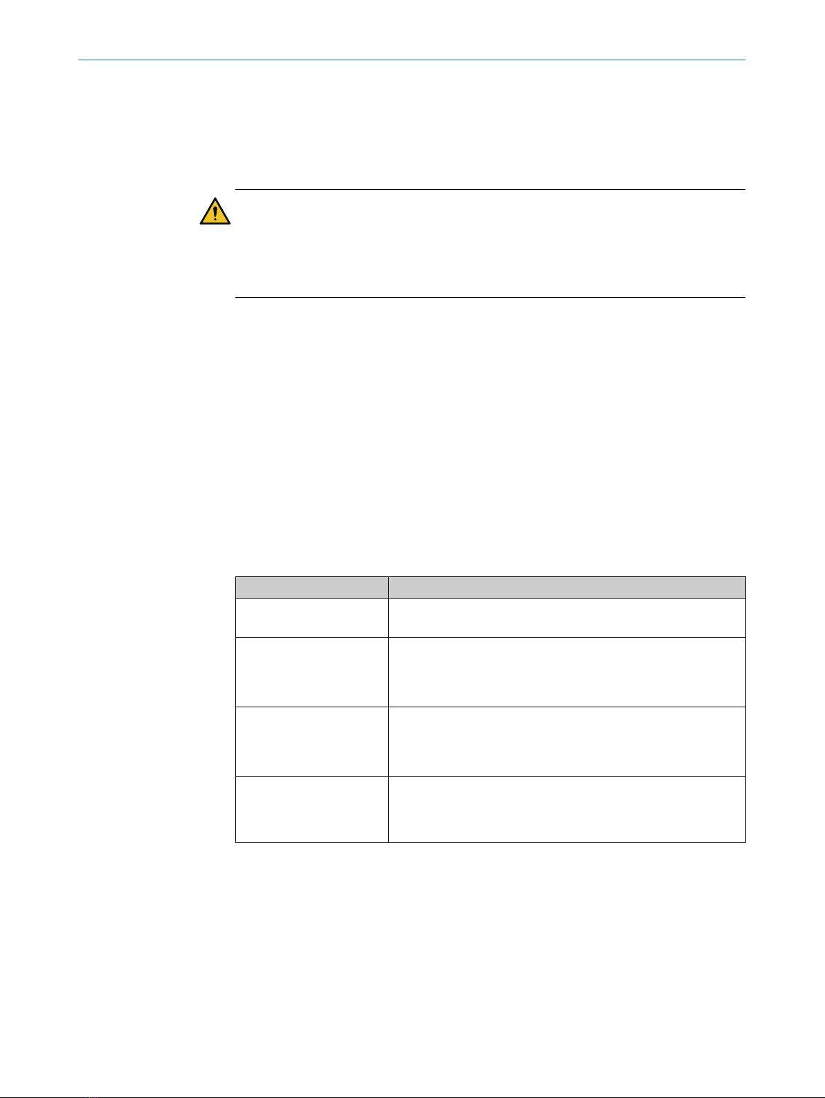
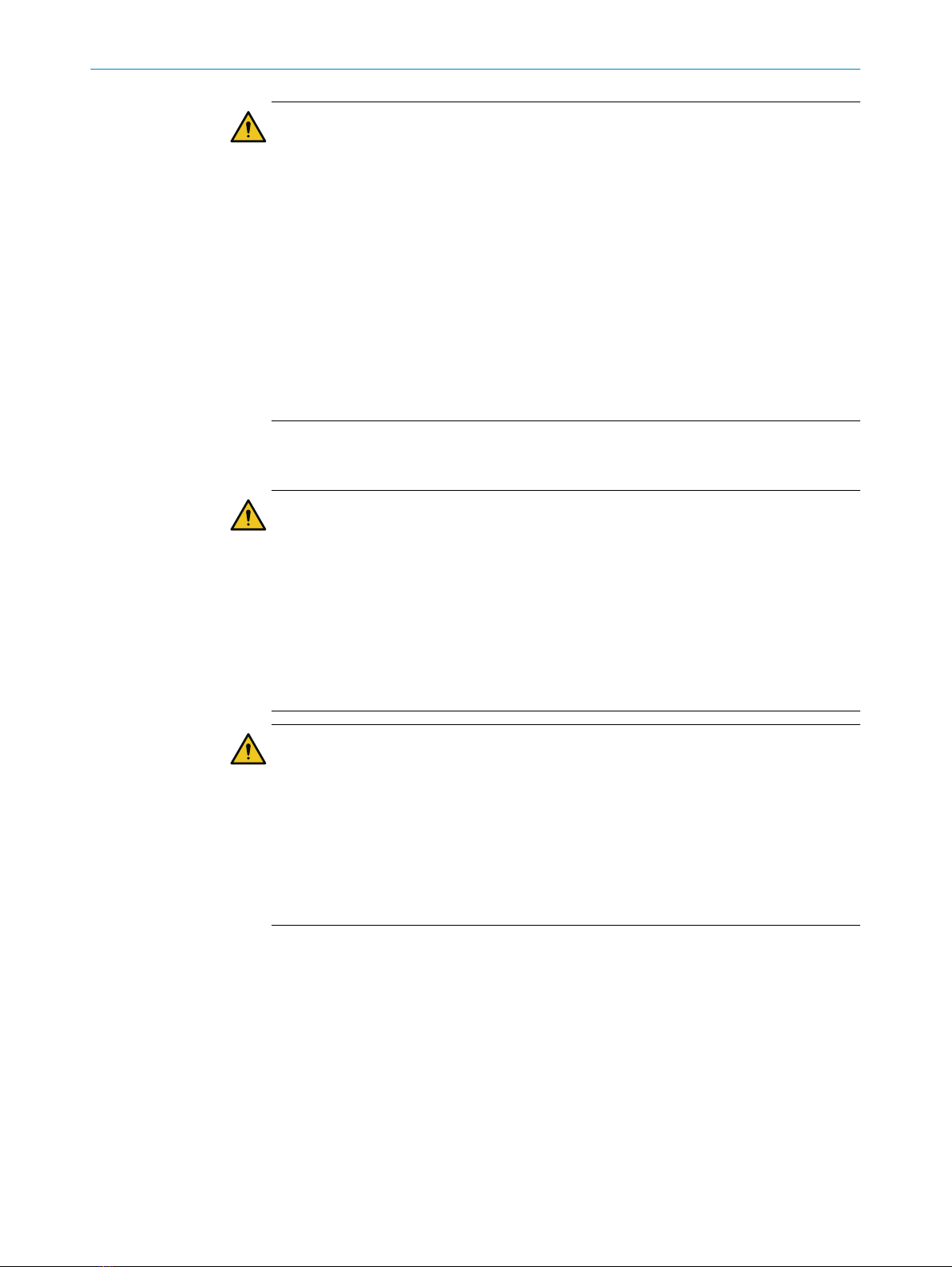
2.7 Warning signs on the device.................................................................... 9
2.8 UL conformity............................................................................................ 10
3 Transport and storage....................................................................... 11
3.1 Transport................................................................................................... 11
3.2 Transport inspection................................................................................. 11
3.3 Storage...................................................................................................... 11
4 Mounting............................................................................................. 12
4.1 Mounting instructions............................................................................... 12
4.2 Mounting the device................................................................................. 12
5 Electrical installation........................................................................ 13
5.1 Safety......................................................................................................... 13
5.2 Wiring instructions.................................................................................... 13
5.3 Connecting the sensor electrically........................................................... 15
6 Operation............................................................................................ 17
6.1 General notes............................................................................................ 17
6.2 Control elements and status indicators.................................................. 17
6.2.1 Indicator lights......................................................................... 17
6.2.2 Display...................................................................................... 18
6.3 Operating options..................................................................................... 19
6.3.1 Operation via pushbuttons and display.................................. 19
6.3.2 Operation via SOPAS ET.......................................................... 20
6.3.3 Operation via SOPASair (Wi-Fi)................................................ 21
6.3.4 Operation via IO-Link............................................................... 21
6.3.5 Operation via multifunctional input (MF)............................... 22
6.4 Description of operation........................................................................... 22
6.4.1 Switching mode for Q1 (“ModeQ1”)......................................... 22
CONTENTS
8017154/1AVV/2021-03-24 | SICK O P E R A T I N G I N S T R U C T I O N S | DT50-2 Pro 3
Subject to change without notice

6.4.2 “Function Q2/Qa” output function........................................... 48
6.4.3 Switching mode for Q2 (“ModeQ2”)......................................... 49
6.4.4 Analog mode for Qa („ModeQa“)............................................. 49
6.4.5 Multifunctional input (“MF Input”).......................................... 57
6.4.6 Speed setting (“Speed”).......................................................... 62
6.4.7 Device settings......................................................................... 63
6.4.8 Read out sensor information.................................................. 67
6.4.9 Other functions........................................................................ 67
7 Maintenance...................................................................................... 73
7.1 Cleaning..................................................................................................... 73
7.2 Maintenance plan..................................................................................... 73
8 Troubleshooting................................................................................. 74
8.1 Detecting and displaying errors............................................................... 74
8.1.1 Operating example via display: Display device status (“Sta‐
tus”).......................................................................................... 74
8.2 Returns...................................................................................................... 75
8.3 Repairs...................................................................................................... 75
8.4 Disposal..................................................................................................... 75
9 Technical data.................................................................................... 76
9.1 Performance............................................................................................. 76
9.2 Interfaces.................................................................................................. 77
9.3 Mechanics/electronics............................................................................. 77
9.4 Ambient data............................................................................................. 77
9.5 Dimensional drawing................................................................................ 78
10 Accessories........................................................................................ 80
11 Appendix............................................................................................. 81
11.1 EU declaration of conformity/Certificates............................................... 81
11.2 Diagram repeatability............................................................................... 81
11.3 Menu structure......................................................................................... 84
11.4 Reference tables....................................................................................... 90
11.4.1 RUN mode................................................................................ 90
11.4.2 Q1 Output.................................................................................. 90
11.4.3 Q2 Output.................................................................................. 92
11.4.4 MF Input................................................................................... 96
11.4.5 Speed....................................................................................... 96
11.4.6 Device....................................................................................... 97
11.4.7 Info............................................................................................ 98
CONTENTS
4O P E R A T I N G I N S T R U C T I O N S | DT50-2 Pro 8017154/1AVV/2021-03-24 | SICK
Subject to change without notice

1 About this document
1.1 Information on the operating instructions
These operating instructions provide important information on how to use devices from
SICK AG.
Prerequisites for safe work are:
•Compliance with all safety notes and handling instructions supplied.
•Compliance with local work safety regulations and general safety regulations for
device applications
The operating instructions are intended to be used by qualified personnel and electrical
specialists.
NOTE
Read these operating instructions carefully to familiarize yourself with the device and its
functions before commencing any work.
The operating instructions are an integral part of the product. Store the instructions
in the immediate vicinity of the device so they remain accessible to staff at all times.
Should the device be passed on to a third party, these operating instructions should be
handed over with it.
These operating instructions do not provide information on operating the machine or
system in which the device is integrated. For more information, refer to the operating
instructions of the specific machine or system.
1.2 Explanation of symbols
Warnings and important information in this document are labeled with symbols. Sig‐
nal words introduce the instructions and indicate the extent of the hazard. To avoid
accidents, damage, and personal injury, always comply with the instructions and act
carefully.
DANGER
… indicates a situation of imminent danger, which will lead to a fatality or serious
injuries if not prevented.
WARNING
… indicates a potentially dangerous situation, which may lead to a fatality or serious
injuries if not prevented.
CAUTION
… indicates a potentially dangerous situation, which may lead to minor/slight injuries if
not prevented.
NOTICE
… indicates a potentially harmful situation, which may lead to material damage if not
prevented.
NOTE
… highlights useful tips and recommendations as well as information for efficient and
trouble-free operation.
ABOUT THIS DOCUMENT 1
8017154/1AVV/2021-03-24 | SICK O P E R A T I N G I N S T R U C T I O N S | DT50-2 Pro 5
Subject to change without notice

1.3 Scope of delivery
Included in scope of delivery:
■Distance sensor
■Protective caps for connections (on the device)
■Printed Safety Notes, multilingual (brief information and general safety notes)
1.4 SICK service
If you require any technical information, our SICK Service will be happy to help. To find
your agency, see the final page of this document.
NOTE
Before calling, make a note of all type label data such as type code, serial number, etc.,
to ensure faster processing.
1.5 Type label
There is a type label on the sensor that provides all relevant information.
1
235
4
SICK AG Waldkirch
Figure 1: Type label
12D code (contents: part number and type designation)
2Type designation
3Article number (order number)
4Year and month of manufacture
5Serial number
1 ABOUT THIS DOCUMENT
6O P E R A T I N G I N S T R U C T I O N S | DT50-2 Pro 8017154/1AVV/2021-03-24 | SICK
Subject to change without notice

2 Safety information
2.1 Intended use
The Dx50-2 distance sensor is a opto-electronic sensor and is used for optical, non-con‐
tact distance measurement of objects.
SICK AG assumes no liability for losses or damage arising from the use of the product,
either directly or indirectly. This applies in particular to use of the product that does not
conform to its intended purpose and is not described in this documentation.
2.2 Improper use
Any use outside of the stated areas, in particular use outside of the technical specifica‐
tions and the requirements for intended use, will be deemed to be incorrect use.
•The device does not constitute a safety component in accordance with the respec‐
tive applicable safety standards for machines.
•The device must not be used in explosion-hazardous areas, in corrosive environ‐
ments or under extreme environmental conditions.
•Any use of accessories not specifically approved by SICK AG is at your own risk.
WARNING
Danger due to improper use!
Any improper use can result in dangerous situations.
Therefore, observe the following information:
■Product should be used only in accordance with its intended use.
■All information in these operating instructions must be strictly observed.
■Shut down the product immediately in case of damage.
2.3 Limitation of liability
Relevant standards and regulations, the latest technological developments, and our
many years of knowledge and experience have all been taken into account when
compiling the data and information contained in these operating instructions. The
manufacturer accepts no liability for damage caused by:
■Non-adherence to the product documentation (e.g., operating instructions)
■Incorrect use
■Use of untrained staff
■Unauthorized conversions or repair
■Technical modifications
■Use of unauthorized spare parts, consumables, and accessories
With special variants, where optional extras have been ordered, or owing to the latest
technical changes, the actual scope of delivery may vary from the features and illustra‐
tions shown here.
2.4 Modifications and conversions
NOTICE
Modifications and conversions to the device may result in unforeseeable dangers.
SAFETY INFORMATION 2
8017154/1AVV/2021-03-24 | SICK O P E R A T I N G I N S T R U C T I O N S | DT50-2 Pro 7
Subject to change without notice

Interrupting or modifying the device or SICK software will invalidate any warranty claims
against SICK AG. This applies in particular to opening the housing, even as part of
mounting and electrical installation.
2.5 Requirements for skilled persons and operating personnel
WARNING
Risk of injury due to insufficient training.
Improper handling of the device may result in considerable personal injury and material
damage.
■All work must only ever be carried out by the stipulated persons.
This product documentation refers to the following qualification requirements for the
various activities associated with the device:
■Instructed personnel have been briefed by the operator about the tasks assigned
to them and about potential dangers arising from improper action.
■Skilled personnel have the specialist training, skills, and experience, as well as
knowledge of the relevant regulations, to be able to perform tasks delegated to
them and to detect and avoid any potential dangers independently.
■Electricians have the specialist training, skills, and experience, as well as knowl‐
edge of the relevant standards and provisions, to be able to carry out work on
electrical systems and to detect and avoid any potential dangers independently.
The electrician must comply with the provisions of the locally applicable work
safety regulation.
The following qualifications are required for various activities:
Table 1: Activities and technical requirements
Activities Qualification
Mounting, maintenance ■Basic practical technical training
■Knowledge of the current safety regulations in the workplace
Electrical installation,
device replacement
■Practical electrical training
■Knowledge of current electrical safety regulations
■Knowledge of the operation and control of the devices in their
particular application
Commissioning, configura‐
tion
■Basic knowledge of the computer operating system used
■Basic knowledge of the design and setup of the described
connections and interfaces
■Basic knowledge of data transmission
Operation of the device for
the particular application
■Knowledge of the operation and control of the devices in their
particular application
■Knowledge of the software and hardware environment for the
particular application
2.6 Operational safety and particular hazards
Please observe the safety notes and the warnings listed here and in other chapters
of this product documentation to reduce the possibility of risks to health and avoid
dangerous situations.
Device types with laser class 1:
Device types with laser class 2:
2 SAFETY INFORMATION
8O P E R A T I N G I N S T R U C T I O N S | DT50-2 Pro 8017154/1AVV/2021-03-24 | SICK
Subject to change without notice

CAUTION
Optical radiation: Laser class 2
The human eye is not at risk when briefly exposed to the radiation for up to 0.25
seconds. Exposure to the laser beam for longer periods of time may cause damage to
the retina. The laser radiation is harmless to human skin.
■Do not look into the laser beam intentionally.
■Never point the laser beam at people's eyes.
■If it is not possible to avoid looking directly into the laser beam, e.g., during
commissioning and maintenance work, suitable eye protection must be worn.
■Avoid laser beam reflections caused by reflective surfaces. Be particularly careful
during mounting and alignment work.
■Do not open the housing. Opening the housing may increase the level of risk.
■Current national regulations regarding laser protection must be observed.
Caution – Use of controls or adjustments or performance of procedures other than
those specified herein may result in hazardous radiation exposure.
WARNING
Electrical voltage!
Electrical voltage can cause severe injury or death.
■Work on electrical systems must only be performed by qualified electricians.
■The power supply must be disconnected when attaching and detaching electrical
connections.
■The product must only be connected to a voltage supply as set out in the require‐
ments in the operating instructions.
■National and regional regulations must be complied with.
■Safety requirements relating to work on electrical systems must be complied with.
WARNING
Risk of injury and damage caused by potential equalization currents!
Improper grounding can lead to dangerous equipotential bonding currents, which may
in turn lead to dangerous voltages on metallic surfaces, such as the housing. Electrical
voltage can cause severe injury or death.
■Work on electrical systems must only be performed by qualified electricians.
■Follow the notes in the operating instructions.
■Install the grounding for the product and the system in accordance with national
and regional regulations.
2.7 Warning signs on the device
Depending on the version of the device, it has a laser of Class 2 or Class 1 installed.
The housing is labeled with a corresponding warning sign.
SAFETY INFORMATION 2
8017154/1AVV/2021-03-24 | SICK O P E R A T I N G I N S T R U C T I O N S | DT50-2 Pro 9
Subject to change without notice

LASER APERTURE
MAX. OUTPUT ≤ 250mW
PULSE LENGHT = 3ns
WAVELENGHT = 658nm
EN/IEC 60825-1:2014
Complies with 21 CFR
1040.10 and 1040.11
except for deviations
pursuant to laser notice
No. 50, dated June 24, 2007
LASER
2
Figure 2: Warning sign on the device: LASER RADIATION: Do not look into the beam. Laser class
2
LASER APERTURE
EN/IEC 60825-1:2014
Complies with 21 CFR
1040.10 and 1040.11
except for deviations
pursuant to laser notice
No. 50, dated June 24, 2007
LASER
1
Figure 3: Warning sign on the device: LASER RADIATION: Do not look into the beam. Laser class
1
2.8 UL conformity
NFPA79 applications only. Adapters including field wiring cables are available.
For more information visit:
bwww.sick.com/Dx50-2
CAUTION
Hazardous radiation!
Using control elements or settings or executing procedures other than those specified
in this document may result in dangerous exposure to radiation.
2 SAFETY INFORMATION
10 O P E R A T I N G I N S T R U C T I O N S | DT50-2 Pro 8017154/1AVV/2021-03-24 | SICK
Subject to change without notice

3 Transport and storage
3.1 Transport
For your own safety, please read and observe the following notes:
NOTICE
Damage to the product due to improper transport.
■The device must be packaged for transport with protection against shock and
damp.
■Recommendation: Use the original packaging as it provides the best protection.
■Transport should be performed by trained specialist staff only.
■The utmost care and attention is required at all times during unloading and
transportation on company premises.
■Note the symbols on the packaging.
■Do not remove packaging until immediately before you start mounting.
3.2 Transport inspection
Immediately upon receipt in Goods-in, check the delivery for completeness and for any
damage that may have occurred in transit. In the case of transit damage that is visible
externally, proceed as follows:
•Do not accept the delivery or only do so conditionally.
•Note the scope of damage on the transport documents or on the transport compa‐
ny's delivery note.
•File a complaint.
NOTE
Complaints regarding defects should be filed as soon as these are detected. Damage
claims are only valid before the applicable complaint deadlines.
3.3 Storage
Store the device under the following conditions:
•Do not store outdoors.
•Store in a dry area that is protected from dust.
•Do not expose to any aggressive substances.
•Protect from sunlight.
•Avoid mechanical shocks.
•Storage temperature: see "Technical data", page 76.
•Relative humidity: see "Technical data", page 76.
•For storage periods of longer than 3 months, check the general condition of all
components and packaging on a regular basis.
TRANSPORT AND STORAGE 3
8017154/1AVV/2021-03-24 | SICK O P E R A T I N G I N S T R U C T I O N S | DT50-2 Pro 11
Subject to change without notice

4 Mounting
4.1 Mounting instructions
•Observe the technical data.
•Protect the sensor from direct sunlight.
•To prevent condensation, avoid exposing the device to rapid changes in tempera‐
ture.
•The mounting site has to be designed for the weight of the device.
4.2 Mounting the device
1. Mount the distance sensor using the provided fixing holes, see "Dimensional
drawing", page 78.
2. Make the electrical connection. Attach and tighten a voltage-free cable, see "Con‐
necting the sensor electrically", page 15.
3. Switch on the supply voltage.
✓The green operating LED lights up.
4. Align the light spot so that the desired object is measured.
4 MOUNTING
12 O P E R A T I N G I N S T R U C T I O N S | DT50-2 Pro 8017154/1AVV/2021-03-24 | SICK
Subject to change without notice

5 Electrical installation
5.1 Safety
WARNING
Personal injury due to improper supply voltage!
■Only operate the device using safety extra-low voltage and safe electrical insula‐
tion as per protection class III.
NOTICE
Equipment damage or unpredictable operation due to working with live parts.
Working with live parts may result in unpredictable operation.
■Only carry out wiring work when the power is off.
■Only connect and disconnect electrical connections when the power is off.
5.2 Wiring instructions
NOTE
Pre-assembled cables can be found online at:
•www.sick.com/Dx50-2
NOTICE
Faults during operation and device or system defects!
Incorrect wiring may result in operational faults and defects.
■Follow the wiring notes precisely.
Recommendation: use shielded cables.
The electrical connection of the device is configured as an M12 round connector.
The enclosure rating stated in the technical data is achieved only with a screwed plug
connector or cover cap.
Shielding requirements
■To ensure a fault-free data transmission, an effective and comprehensive shielding
solution must be implemented.
■Apply a cable shield at each end, i.e. in the control cabinet and at the device. The
cable shield of the pre-assembled cables is connected to the knurled nut and thus
also to a large area of the device housing.
■The cable shield in the control cabinet must be connected to a large area of the
signal ground.
■Take appropriate measures to prevent equipotential bonding currents flowing
through the cable shield.
■During installation, pay attention to the different cable groups. The cables are
grouped into the following four groups according to their sensitivity to interference
or radiated emissions:
°Group 1: cables very sensitive to interference, such as analog measuring
cables
°Group 2: cables sensitive to interference, such as device cables, communica‐
tion signals, bus signals
ELECTRICAL INSTALLATION 5
8017154/1AVV/2021-03-24 | SICK O P E R A T I N G I N S T R U C T I O N S | DT50-2 Pro 13
Subject to change without notice

°Group 3: cables that are a source of interference, such as control cables for
inductive loads and motor brakes
°Group 4: cables that are a powerful source of interference, such as out‐
put cables from frequency inverters, welding system power supplies, power
cables
bCables in groups 1, 2 and 3, 4 must be crossed at right angles (see figure 4).
bRoute the cables in groups 1, 2 and 3, 4 in different cable channels or use
metallic separators (see figure 5 and see figure 6). This applies particularly
if cables of devices with a high level of radiated emission, such as frequency
converters, are laid parallel to device cables.
1
2
4
3
1
2
4
3
90
90
Figure 4: Cross cables at right angles
1
2
3
4
Figure 5: Ideal laying – Place cables in different cable channels
1
23
4
Figure 6: Alternative laying – Separate cables with metallic separators
5 ELECTRICAL INSTALLATION
14 O P E R A T I N G I N S T R U C T I O N S | DT50-2 Pro 8017154/1AVV/2021-03-24 | SICK
Subject to change without notice

Figure 7: Shield connection in plastic housings
NOTE
Use an appropriate earthing method to prevent equipotential bonding currents flowing
through the cable shield.
5.3 Connecting the sensor electrically
NOTE
The connection diagram and information on inputs and outputs can be found on the
side plate of the sensor.
NOTICE
All electrical circuits must be connected to the device with safety or protective extra-low
voltage (SELV or PELV).
1. Ensure that the power supply is not connected.
2. Connect the sensor according to the connection diagram.
3. Observe the wiring instructions, see "Wiring instructions", page 13.
1
2
4
3
5
L+
1
brn
M
3
blu
Q1/C
4
blk
QA/Q2/
¯
Q1/–
2
wht
MF
5
gra 1
Figure 8: Connection diagram, 5-pin plug
1Multifunctional input
Table 2: Legend for connection diagram
Contact Marking Wire color Description
1 L+ Brown Supply voltage: +10 to 30 V DC
2 QA/Q2/Q1/- White Output 2: analog output / output signal
switching device 2 / Q1 not / inactive
3 M Blue Supply voltage: 0 V
ELECTRICAL INSTALLATION 5
8017154/1AVV/2021-03-24 | SICK O P E R A T I N G I N S T R U C T I O N S | DT50-2 Pro 15
Subject to change without notice

Contact Marking Wire color Description
4 Q1/C Black Output 1: output signal switching device
1 / IO-Link
5 MF Gray Multifunctional input (MF)
5 ELECTRICAL INSTALLATION
16 O P E R A T I N G I N S T R U C T I O N S | DT50-2 Pro 8017154/1AVV/2021-03-24 | SICK
Subject to change without notice

6 Operation
NOTICE
Pushbutton damage due to improper handling.
Improper handling of the pushbuttons can damage them. This will make operation
difficult or impossible.
■Only operate the pushbuttons with your fingers or a suitable pointing device.
■Do not operate the pushbuttons using sharp or hard objects.
NOTE
For basic instructions for the display and control elements see "Control elements and
status indicators", page 17. Briefly pressing the pushbutton changes from the
measured value display to the menu level.
For the overall menu structure see "Menu structure", page 84.
6.1 General notes
If the sensor is unable to measure, adjust the measuring speed or optimize the align‐
ment.
For a successful teach operation, the sensor must be able to measure. The distance
to the teach object must not change during the teach operation. The object must be
in the measuring range, and the distance values taught in for the near-sensor distance
and far-sensor distance must not be exactly the same during a switching window or the
analog scaling.
To prevent EMC interference, observe the wiring instructions. If an environment is
disrupted by EMC interference, data output via IO-Link is the preferred solution. If the
application requires an output of the measured values in such an environment via the
analog output, an analog current output should also be preferred to using the voltage
output, because this is significantly less susceptible to EMC interference.
NOTE
The switching mode and the settings can be changed by executing a teach function by
means of a multifunctional input (see "Multifunctional input (“MF Input”)", page 57) or
IO-Link (see "Operation via IO-Link", page 21).
NOTE
The LEDs, the process data bits of the outputs in IO-Link and the output visualization
in SOPAS display the logical status of the outputs. This does not necessarily correspond
to the electrical level of the switching outputs. The electrical level of an output depends
on the setting of the corresponding logic, the output circuit (NPN or PNP) and the logical
status of the output. The examples in this document refer to a PNP circuit.
6.2 Control elements and status indicators
6.2.1 Indicator lights
1
2
3
1Operating LED (green)
OPERATION 6
8017154/1AVV/2021-03-24 | SICK O P E R A T I N G I N S T R U C T I O N S | DT50-2 Pro 17
Subject to change without notice

2Status LED Q1 (orange)
3Status LED Q2 / QA (orange)
Table 3: Meaning of the indicator lights
Display Condition Meaning
Status indicator (1) Power supply available, sensor ready
for use
Power supply not available
Power supply available, sensor ready
for use, connection to an IO-Link
master available
Output display Q1 (2) Switching output active
Switching output not active
Output display Q2/QA (3) Switching output active or measured
value within the scaling range for the
analog output
Switching output not active or meas‐
ured value outside the scaling range
for the analog output
Output displays Q1 (2) and
Q2/QA (3) simultaneously Teach-in operation is carried out
5 seconds in alter‐
nation
Teach-in operation has failed
Permanently in
alternation
There is a fault
Does not light up
Flashing
Permanently on
6.2.2 Display
The display with keyboard can be used to call up measurement data and diagnostic
data as well as to modify device parameters. The display is on the top side of the
sensor. After the sensor is switched on it is in RUN mode. Pressing the pushbutton
switches between the following display values:
Table 4: Displays in RUN mode
Display Symbol in front
of the display
value
Meaning
Distance Measured distance in millimeters or “NoDist”/“Max”/“Min”,
if a valid measurement is not possible
Signal level SL Absolute value (level) of the received measurement signal,
see "Signal level (“SL”)"
Signal quality SQ Signal quality in the form of a percentage (stability of the
measurement, see "Signal quality (“SQ”)")
Temperature +/- Temperature within the sensor in °C.
6 OPERATION
18 O P E R A T I N G I N S T R U C T I O N S | DT50-2 Pro 8017154/1AVV/2021-03-24 | SICK
Subject to change without notice

Display Symbol in front
of the display
value
Meaning
Shape match SH Shape comparison: Degree to which the last viewed object
matches the taught-in reference object in % (only availa‐
ble in the “Shape match” mode, see "“Shape comparison”
(“Shape”) switching mode", page 36
Briefly pressing the pushbutton in Run mode opens the menu.
Briefly pressing the and pushbuttons switches between the various menu
levels. Briefly pressing the pushbutton repeatedly always takes you back to RUN
mode.
If no pushbutton has been pressed over a period of 5 minutes, the sensor automatically
returns to RUN mode and displays the measured distance.
6.3 Operating options
The DT50-2 Pro distance sensor provides various operating options. These are descri‐
bed in the following chapters For more details about the various operating options, refer
to the reference table, see "Reference tables", page 90.
6.3.1 Operation via pushbuttons and display
6.3.1.1 Measured value display
As soon as the measuring device is supplied with voltage, the display shows the current
measured value.
6.3.1.2 Opening the menu
Briefly pressing the pushbutton in RUN mode opens the menu.
6.3.1.3 Selecting parameters
You can select a menu item, parameter, or option using the or pushbuttons and
confirm these with . The menu path is specified in the respective chapters. For the
overall menu structure see "Menu structure", page 84.
6.3.1.4 Selecting an option
1. Use the or pushbutton to select the desired parameter and confirm this
with .
2. Select the desired option using the or pushbutton.
3. Perform one of the following steps:
■Press the pushbutton to save the change.
■Press the pushbutton to cancel the process. The previously selected
parameter name is displayed again.
4. Perform one of the following steps to return to the measured value display:
■Press the pushbutton repeatedly until the measured value is displayed
again.
■Wait for approx. 5 minutes. The display will automatically switch back to the
measured value display if no pushbuttons are pressed. Any settings you have
made will also be saved.
OPERATION 6
8017154/1AVV/2021-03-24 | SICK O P E R A T I N G I N S T R U C T I O N S | DT50-2 Pro 19
Subject to change without notice

6.3.1.5 Changing the value
1. Select the desired parameter using the and pushbuttons.
2. Press the pushbutton.
✓The current value of the parameter is displayed. The first digit on the left flashes.
3. Press the pushbutton to increase the digit. Press the pushbutton to
decrease the digit.
4. Press the pushbutton to confirm the digit entered.
The next digit flashes. Press the pushbutton to cancel the process.
5. Repeat steps 3 and 4 until the last digit has been confirmed and the setting has
been saved.
✓The parameter name is displayed.
6. Press the pushbutton repeatedly until the measured value is displayed again.
Alternatively, you can wait 5 minutes.
✓The display will switch back to the measured value display.
6.3.1.6 Display of the menu level
The current menu level is shown at the left edge of the display, see "Menu structure",
page 84:
Table 5: Display of the menu level
Display Menu level
RUN Measured value display
RUN / SET Menu level 1
SET Menu level 2
SET / MEN Menu level 3
MEN Menu level 4
6.3.1.7 User level
The two user levels “Easy” and “Advanced” are available for operating the display. They
differ in the scope of available parameters. In the “Easy” user level, you can view the
parameters that are frequently needed. In the “Advanced” user level, you can view all
parameters.
The “Easy” user level is set by default. You can change the user level in the menu under
Device > User, see "Operating example via display: Change user level to Advanced",
page 64.
6.3.2 Operation via SOPAS ET
The SOPAS Engineering Tool (SOPAS ET) software can be used for configuring parame‐
ters and for service and diagnostic purposes.
The following is required for configuring the sensor's parameters using a computer:
– A computer with SOPAS ET installed and a free USB2.0-compatible port
– SICK SiLink2 Master (Order No. 1061790)
– Connection cable with M12 male and female connectors, 5-pin (e.g. Order No.
6025930)
Connect the sensor to the SiLink2 Master via the connection cable. Connect the
SiLink2 Master to the computer via the accompanying USB cable. If the computer's
USB port cannot provide the required power for operating SiLink2 Master and sensor,
also connect SiLink2 Master to the accompanying AC adapter.
6 OPERATION
20 O P E R A T I N G I N S T R U C T I O N S | DT50-2 Pro 8017154/1AVV/2021-03-24 | SICK
Subject to change without notice
Table of contents
Other SICK Accessories manuals

SICK
SICK RMS1000 User manual

SICK
SICK WTB4F User manual

SICK
SICK GRL18V User manual

SICK
SICK WTF26 User manual

SICK
SICK C30-21 163 Series User manual

SICK
SICK LMS1104C-111031S01 User manual

SICK
SICK WSE26 User manual

SICK
SICK EDS35-2 Series User manual

SICK
SICK PBS Hygienic Series User manual

SICK
SICK PowerProx Micro WTT2SL Series User manual

SICK
SICK GTE6 Series User manual

SICK
SICK WLD26 User manual

SICK
SICK WTL16 User manual

SICK
SICK PSS Prime User manual

SICK
SICK KTML Series User manual

SICK
SICK MLS User manual

SICK
SICK WSE16 Series User manual

SICK
SICK GRL18 Series User manual

SICK
SICK WSO26 A0 Series User manual

SICK
SICK GRTE18V User manual