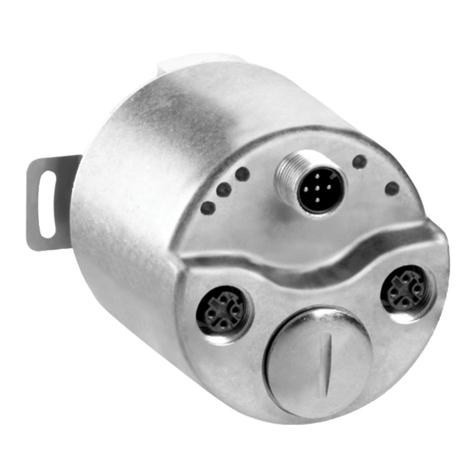
SICK EtherNet/IP AFS60 User manual

OPERATING INSTRUCTIONS
AFS/AFM60 EtherNet/IP
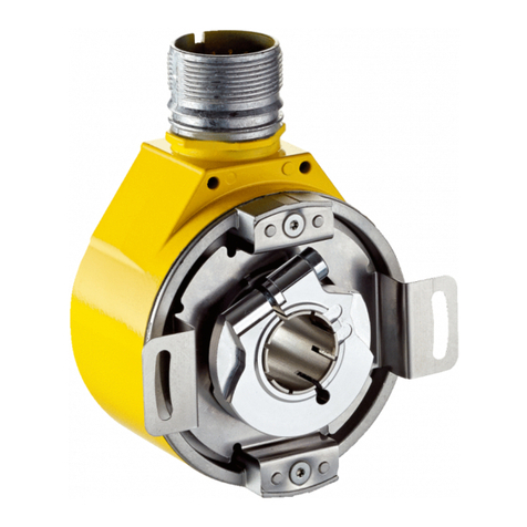
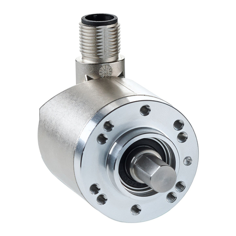
Absolute encoder

Described product
AFS/AFM60 EtherNet/IP
Manufacturer
SICK AG
Erwin-Sick-Str. 1
79183 Waldkirch
Germany
Legal information
This work is protected by copyright. Any rights derived from the copyright shall be
reserved for SICK AG. Reproduction of this document or parts of this document is
only permissible within the limits of the legal determination of Copyright Law. Any modi‐
fication, abridgment or translation of this document is prohibited without the express
written permission of SICK AG.
The trademarks stated in this document are the property of their respective owner.
© SICK AG. All rights reserved.
Original document
This document is an original document of SICK AG.
2O P E R A T I N G I N S T R U C T I O N S | AFS/AFM60 EtherNet/IP 8014213/1EF3/2021-12-08 | SICK
Subject to change without notice
Contents
1 About this document........................................................................ 6
1.1 Scope......................................................................................................... 6
1.2 Purpose of this document........................................................................ 6
1.3 Target group.............................................................................................. 6
1.4 Further information................................................................................... 6
1.5 Symbols and document conventions...................................................... 7
1.6 Abbreviations used................................................................................... 7
2 Safety information............................................................................ 9
2.1 General notes............................................................................................ 9
2.2 Intended use............................................................................................. 9
2.3 Requirements for the qualification of personnel.................................... 9
3 Product description........................................................................... 11
3.1 Product identification............................................................................... 11
3.2 Specific features....................................................................................... 12
3.3 Operating principle of the encoder.......................................................... 13
3.3.1 Scalable resolution.................................................................. 13
3.3.2 Preset function......................................................................... 13
3.3.3 Round axis functionality.......................................................... 14
3.4 Integration in EtherNet/IP........................................................................ 15
3.4.1 EtherNet/IP architecture......................................................... 15
3.4.2 Communication in EtherNet/IP............................................... 16
3.5 CIP object model....................................................................................... 18
3.5.1 Supported classes................................................................... 18
3.5.2 Identity object.......................................................................... 20
3.5.3 Assembly object....................................................................... 22
3.5.4 Position sensor object............................................................. 27
3.6 Integration and configuration options..................................................... 34
3.6.1 Integration in EtherNet/IP....................................................... 34
3.6.2 Configuration............................................................................ 34
3.7 Parameterizable functions....................................................................... 36
3.7.1 Saving and resetting configuration......................................... 36
3.7.2 IP address................................................................................ 38
3.7.3 Slave sign of life....................................................................... 38
3.7.4 Code sequence........................................................................ 38
3.7.5 Scaling...................................................................................... 39
3.7.6 Increments per revolution....................................................... 39
3.7.7 Total resolution/measuring range.......................................... 39
3.7.8 Preset function......................................................................... 40
3.7.9 Speed measurement unit....................................................... 40
3.7.10 Round axis functionality.......................................................... 40
3.8 Operating elements and status indicators.............................................. 41
CONTENTS
8014213/1EF3/2021-12-08 | SICK O P E R A T I N G I N S T R U C T I O N S | AFS/AFM60 EtherNet/IP 3
Subject to change without notice

4 Commissioning.................................................................................. 43
4.1 Electrical installation................................................................................ 43
4.1.1 Encoder connections............................................................... 43
4.2 Settings on the hardware......................................................................... 44
4.2.1 IP address setting.................................................................... 44
4.2.2 Triggering a preset value with the preset pushbutton........... 45
5 Configuration using a PLC................................................................ 46
5.1 Delivery state............................................................................................ 46
5.2 IP address of the encoder........................................................................ 46
5.2.1 Without DHCP server............................................................... 46
5.2.2 Assigning the IP address via DHCP........................................ 46
5.2.3 Freezing the assigned IP address........................................... 49
5.2.4 Checking integration into EtherNet/IP via RSLinx Classic.... 50
5.3 Creating a project in the control software............................................... 51
5.4 Integration and configuration using an EDS file..................................... 52
5.4.1 Requirements........................................................................... 52
5.4.2 Setting up communication...................................................... 53
5.4.3 Configuration............................................................................ 55
5.5 Installing the ladder routine..................................................................... 56
5.5.1 Import of the ladder routine.................................................... 56
5.5.2 Integration as SubRoutine in MainRoutine............................ 61
5.5.3 Using the SubRoutine.............................................................. 62
5.5.4 Reading out and changing parameters of the encoder........ 63
5.6 Function block........................................................................................... 66
5.6.1 Requirements........................................................................... 66
5.6.2 Import and wiring..................................................................... 66
5.7 Integration of the encoder as generic module........................................ 67
5.7.1 Module settings....................................................................... 68
5.7.2 Downloading the configuration to the control........................ 70
5.7.3 Checking communication........................................................ 71
5.8 Programming examples............................................................................ 71
5.8.1 Reading out temperature........................................................ 72
5.8.2 Setting preset value................................................................. 82
6 Configuration using the integrated web server............................. 94
6.1 Home......................................................................................................... 95
6.1.1 Device....................................................................................... 95
6.1.2 Position..................................................................................... 95
6.1.3 Speed....................................................................................... 95
6.1.4 Temperature............................................................................. 95
6.1.5 Timer......................................................................................... 95
6.2 Parameterization....................................................................................... 96
6.2.1 Overview................................................................................... 97
6.2.2 Units.......................................................................................... 97
6.2.3 Changing preset value............................................................. 98
CONTENTS
4O P E R A T I N G I N S T R U C T I O N S | AFS/AFM60 EtherNet/IP 8014213/1EF3/2021-12-08 | SICK
Subject to change without notice
6.2.4 Triggering preset...................................................................... 98
6.2.5 Scaling...................................................................................... 99
6.2.6 Round axis functionality.......................................................... 99
6.2.7 Limits........................................................................................ 100
6.2.8 Reset........................................................................................ 101
6.3 Diagnostics................................................................................................ 101
6.3.1 Status....................................................................................... 101
6.3.2 Speed....................................................................................... 102
6.3.3 Temperature............................................................................. 102
6.3.4 Time.......................................................................................... 102
6.3.5 Cycles....................................................................................... 103
6.3.6 Heartbeat................................................................................. 103
6.4 Tools........................................................................................................... 103
6.4.1 EDS........................................................................................... 103
6.4.2 Ladder routine......................................................................... 103
6.4.3 Update...................................................................................... 104
6.4.4 Address switch......................................................................... 105
6.4.5 Fault header information......................................................... 105
6.5 Test notes.................................................................................................. 105
7 Troubleshooting................................................................................. 106
7.1 Response to errors................................................................................... 106
7.2 Support...................................................................................................... 106
7.3 Diagnostics................................................................................................ 106
7.3.1 Error and status indications of the LEDs............................... 106
7.3.2 Self test via EtherNet/IP.......................................................... 107
7.3.3 Warnings, alarms and errors via EtherNet/IP........................ 107
7.3.4 Error messages of the Allen Bradley control system............. 110
8 Annex.................................................................................................. 112
8.1 Conformities and certificates................................................................... 112
8.1.1 Compliance with EU directives................................................ 112
8.1.2 Compliance with UK statutory instruments........................... 112
CONTENTS
8014213/1EF3/2021-12-08 | SICK O P E R A T I N G I N S T R U C T I O N S | AFS/AFM60 EtherNet/IP 5
Subject to change without notice

1 About this document
1.1 Scope
NOTE
These operating instructions apply to the AFS60/AFM60 EtherNet/IP absolute encoder
with the following type designations:
•Singleturn encoder = AFS60A-xxIx262144
•Multiturn encoder = AFM60A-xxIx018x12
1.2 Purpose of this document
These operating instructions instruct the technical personnel of the machine manufac‐
turer or machine operator in:
•Electrical installation
•Commissioning
•Parameterization
•Operation
•Maintenance
These operating instructions must be made available to all persons who work with the
encoder.
The official and legal regulations for operating the encoder must always be complied
with.
1.3 Target group
These operating instructions are intended for planning engineers, developers, and oper‐
ators of plants and systems into which one or more AFS/AFM60 EtherNet/IP Absolute
encoder are to be integrated. They are also intended for people who put the encoder
into operation for the first time or who are in charge of maintenance.
These instructions are written for trained persons who are responsible for the installa‐
tion, mounting and operation of the encoder in an industrial environment.
Only trained electricians are permitted to carry out work on the electrical system or
electrical assemblies.
NOTICE
bRead the operating instructions carefully and ensure that you have understood the
contents completely before you work with the encoder.
1.4 Further information
These operating instructions do not contain any information on mounting, technical
data and dimensional drawings. These are enclosed separately with the device or
available via the Internet: www.sick.com
The following information is available via the Internet:
•Mounting instructions
•Data sheets
•CAD data for drawings and dimensional drawings
•Certificates (such as the EU declaration of conformity)
1 ABOUT THIS DOCUMENT
6O P E R A T I N G I N S T R U C T I O N S | AFS/AFM60 EtherNet/IP 8014213/1EF3/2021-12-08 | SICK
Subject to change without notice

1.5 Symbols and document conventions
Safety notes
DANGER
A safety note informs you of real-world specifications for safely mounting and installing
the absolute encoder.
This is intended to protect you against accidents.
bRead the safety notes carefully and follow them.
Information on property damage/general advice
NOTICE
Indicates important information and possible property damage.
NOTE
Indicates useful tips and recommendations.
Instructions
bInstructions requiring specific action are indicated by an arrow. Carefully read and
follow the instructions for action.
1. The sequence of instructions for action is numbered.
2. Numbered instructions for action are to be followed in the given order.
Status indicators
LED symbols describe the status of a diagnostics LED. Examples:
The LED is illuminated continuously.
The LED is flashing.
The LED is off.
1.6 Abbreviations used
CIP Common Industrial Protocol
CMR Counts per Measuring Range
CNR_D Customized Number of Revolutions, Divisor = denominator of the customized number of
revolutions
CNR_N Customized Number of Revolutions, Nominator = nominator of the customized number
of revolutions
CPR Counts Per Revolution
DHCP Dynamic Host Control Protocol
DLR Device Level Ring
EADK EtherNet/IP Adapter Developers Kit = development environment for EtherNet/IP devi‐
ces
EDS Electronic Data Sheet
EEPROM Electrically Erasable Programmable Read-only Memory
FPGA Field Programmable Gate Array = electronic component that can be programmed to
form an application-specific circuit
ABOUT THIS DOCUMENT 1
8014213/1EF3/2021-12-08 | SICK O P E R A T I N G I N S T R U C T I O N S | AFS/AFM60 EtherNet/IP 7
Subject to change without notice

I/O Input and Output Data (from the point of view of the master)
IP in TCP/IP Internet Protocol
IP in EtherNet/IP Industrial Protocol
MAC Media Access Control
ODVA Open DeviceNet Vendor Association
PLC Programmable Logic Controller
TCP Transmission Control Protocol
UDP User Datagram Protocol = connectionless network protocol
1 ABOUT THIS DOCUMENT
8O P E R A T I N G I N S T R U C T I O N S | AFS/AFM60 EtherNet/IP 8014213/1EF3/2021-12-08 | SICK
Subject to change without notice
2 Safety information
2.1 General notes
DANGER
Observe the following to ensure the safe use of the AFS/AFM60 EtherNet/IP as
intended.
The encoder must be installed and maintained by trained, qualified personnel with
knowledge of electronics, precision engineering, and controller programming. The rele‐
vant technical safety standards must be observed.
All persons entrusted with the installation, operation, or maintenance of the devices
must follow the safety guidelines:
•The operating instructions must always be available and must be followed.
•Unqualified personnel must stay away from the system during installation and
maintenance.
•The system must be installed in accordance with the applicable safety regulations
and mounting instructions.
•The work safety regulations of the employers’ liability insurance associations and
trade associations in the respective country must be observed during installation.
•Failure to observe the relevant work safety regulations may lead to physical injury
or cause damage to the system.
•The current and voltage sources in the encoder are designed in accordance with
the applicable technical guidelines.
2.2 Intended use
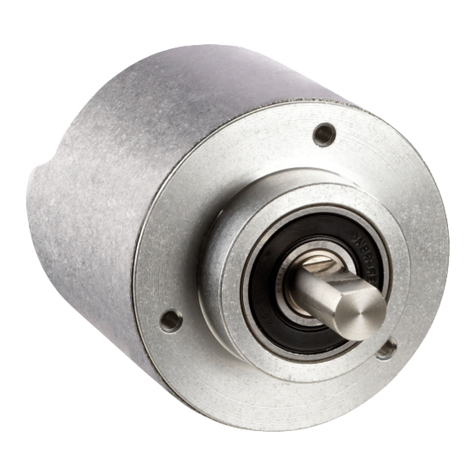
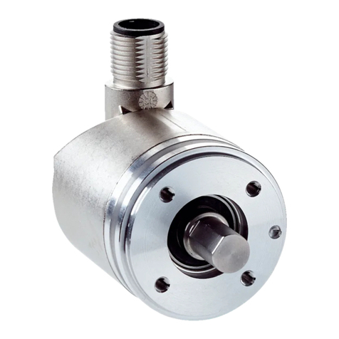
The Absolute encoder AFS/AFM60 EtherNet/IP is a measuring device which is manu‐
factured according to the recognized industrial regulations and which meets the quality
requirements stipulated in ISO 9001:2008 as well as those relating to environmental
management systems as defined in ISO 14001:2009.
An encoder is designed for mounting and can only be operated according to its
intended function. For this reason, the encoder is not equipped with direct safety
devices.
The system designer must provide measures to ensure the safety of persons and
systems in accordance with the legal guidelines.
Due to its design, the AFS/AFM60 EtherNet/IP may only be operated within an Ether‐
Net/IP network. The EtherNet/IP specifications and the guidelines for setting up an
EtherNet/IP network must be observed.
In the event of any other usage or modification to the AFS/AFM60 EtherNet/IP (e.g.,
due to opening the housing during mounting and electrical installation) or in the event
of changes made to the SICK software, any claims against SICK AG under the warranty
will be rendered void.
2.3 Requirements for the qualification of personnel
The encoder must only be mounted, commissioned, and maintained by authorized
personnel.
NOTE
Repair work on the encoder may only be performed by qualified and authorized service
personnel from SICK AG.
The following qualifications are necessary for the various tasks:
SAFETY INFORMATION 2
8014213/1EF3/2021-12-08 | SICK O P E R A T I N G I N S T R U C T I O N S | AFS/AFM60 EtherNet/IP 9
Subject to change without notice

Table 1: Authorized personnel
Task Qualification
Mounting (see mount‐
ing instructions)
•Basic practical technical training
•Knowledge of the current safety regulations in the workplace
Electrical installation
and device replace‐
ment
•Practical electrical training
•Knowledge of current electrical safety regulations
•Knowledge of the operation and control of the devices in their
particular application (e.g., industrial robots, storage and conveyor
systems)
Commissioning, oper‐
ation, and configura‐
tion
•Knowledge of the current safety regulations and of the operation
and control of the devices in their particular application
•Knowledge of automation systems (e.g. Rockwell ControlLogix con‐
troller)
•Knowledge of EtherNet/IP
•Knowledge of the use of automation software (e.g. with Rockwell
RSLogix)
2 SAFETY INFORMATION
10 O P E R A T I N G I N S T R U C T I O N S | AFS/AFM60 EtherNet/IP 8014213/1EF3/2021-12-08 | SICK
Subject to change without notice
3 Product description
3.1 Product identification
NOTICE
The year of construction of the absolute encoder can be found on the device label or on
the packaging label. Keep the packaging for this reason.
Solid shaft type code
Table 2: Solid shaft type code
1 2 3 4 5 6 7 8 9 10 11 12 13 14 15 16
A F S 6 0 A - S
Table 3: Solid shaft type code - explanation
Position Meaning Description
1 Product family A = Absolute
2 Technology F = Optical scanning with high resolution and accuracy
3 Type S = Singleturn
M = Multiturn
4 Size 60 = Outer diameter approx. 60 mm
5
6 Step count 1) A = Number of steps per revolution max. = 262,144
(18 bit)
7 - -
8 Type S = Solid shaft
9 Mechanical design 1 = Servo flange, 6 x 10 mm
4 = Face mount flange, 10 x 19 mm
5 = Face mount flange, 10 x 19 mm round
6 = Face mount flange, 3/8" round
7 = Face mount flange, 3/8"
10 Electrical interface I = EtherNet/IP
11 Connection type B = 3 x M12, 4-pin, axial
12 Resolution Singleturn: Number of steps per revolution, can be freely
programed by customer: Type A = 2 ... 262144 (factory
setting)
Multiturn: 018x12, type A: 18 bit (singleturn) x 12 bit
multiturn (factory setting)
13
14
15
16
1) Number of steps per revolution of programmable devices: Singleturn: Between 4 ... 262144. Programma‐
ble via programming tool and Safety Designer configuration software (www.sick.com).
Blind hollow shaft type code
Table 4: Blind hollow shaft type code
1 2 3 4 5 6 7 8 9 10 11 12 13 14 15 16
A F S 6 0 A - B
Table 5: Blind hollow shaft type code – explanation
Position Meaning Description
1 Product family A = Absolute
2 Technology F =
PRODUCT DESCRIPTION 3
8014213/1EF3/2021-12-08 | SICK O P E R A T I N G I N S T R U C T I O N S | AFS/AFM60 EtherNet/IP 11
Subject to change without notice

Position Meaning Description
3 Type S = Singleturn
M = Multiturn
4 Size 60 = Outer diameter approx. 60 mm
5
6 Step count 1) A = Number of steps per revolution max. = 262,144
(18 bit)
7 - -
8 Type B = Blind hollow shaft
9 Mechanical design B = Blind hollow shaft 8 mm
C = Blind hollow shaft 3/8"
D = Blind hollow shaft 10 mm
E = Blind hollow shaft 12 mm
F = Blind hollow shaft 1/2"
G = Blind hollow shaft 14 mm
H = Blind hollow shaft 15 mm
J = Blind hollow shaft 5/8"
K = Blind hollow shaft 1/4"
10 Electrical interface I = EtherNet/IP
11 Connection type B = 3 x M12, 4-pin, axial
12 Resolution Singleturn: Number of steps per revolution, can be freely
programed by customer: Type A = 2 ... 262144 (factory
setting)
Multiturn: 018x12, type A: 18 bit (singleturn) x 12 bit
multiturn (factory setting)
13
14
15
16
1) Number of steps per revolution of programmable devices: Singleturn: Between 4 ... 262144. Programma‐
ble via programming tool and Safety Designer configuration software (www.sick.com).
3.2 Specific features
Table 6: Special features of the encoder variants
Features Singleturn encoder Multiturn encoder
Absolute encoder in 60 mm design X X
Rugged nickel code disk for harsh ambient
conditions
X X
High accuracy and availability X X
Large ball bearing distance of 30 mm X X
High vibration resistance X X
Optimum concentricity X X
Compact design X X
Face mount flange, servo flange and blind hol‐
low shaft
X X
18 bit singleturn resolution (1 to
262,144 steps)
X X
30 bit total resolution X
12-bit multiturn resolution (1 to 4,096 revolu‐
tions)
X
Round axis functionality X
Interface (according to IEC 61784-1) X X
3 PRODUCT DESCRIPTION
12 O P E R A T I N G I N S T R U C T I O N S | AFS/AFM60 EtherNet/IP 8014213/1EF3/2021-12-08 | SICK
Subject to change without notice
Features Singleturn encoder Multiturn encoder
Supports encoder profile 22h defined in the
CIP (Common Industrial Protocol)
X X
Device level ring (DLR) X X
3.3 Operating principle of the encoder
The Absolute encoder detects the position and speed of rotary axes and outputs the
position in the form of a unique digital numerical value. Optical detection takes place
via an internal code disk.
The AFS60 is a singleturn encoder
Singleturn encoders are used when one shaft revolution must be detected absolutely.
The AFM60 is a multiturn encoder
Multiturn encoders are used when more than one shaft revolution must be detected
absolutely.
3.3.1 Scalable resolution
The steps per revolution or the total resolution can be scaled and adapted to the
respective application.
The steps per revolution are scalable from 1 ... 262,144 in whole numbers. The total
resolution of the AFM60 must be 2ⁿ-fold the steps per revolution. This restriction is not
relevant if the round axis functionality is activated.
3.3.2 Preset function
A preset value can be used to set the position value of the encoder. I. e. the encoder
can be set to any position within the measuring range. This allows, for example, the zero
position of the encoder to be aligned with the machine zero point.
2
3
5
44
6
1
Figure 1: Setting a preset value
1Setting a preset value
2When switching on again
3Actual position value
4Offset
5Position value after preset
6Position value after switching on again
PRODUCT DESCRIPTION 3
8014213/1EF3/2021-12-08 | SICK O P E R A T I N G I N S T R U C T I O N S | AFS/AFM60 EtherNet/IP 13
Subject to change without notice

When the encoder is switched off, the offset – the delta between the real position
value and the value specified by preset – is saved. When switching on again, the
new calculated position value is formed from the new real position value and the
offset. Even if the encoder was turned further during the switched-off state, the correct
position value is output as a result.
3.3.3 Round axis functionality
The encoder supports the gear function for round axes. Here, the steps per revolution
are set as a fraction (see "Preset function", page 13). This allows a number that is not
2ⁿ-fold the steps per revolution or/and a decimal number (e.g. 12.5) to be configured
as the total resolution.
NOTE
The output position value is calculated with a zero point correction, the set code
sequence and the entered gear parameters.
Example with transmission ratio
A rotating table for filling bottles is to be controlled. The steps per revolution are
specified by the number of fillers. There are nine fillers available. 1000 steps are
required for precise measurement of the distance between two fillers.
1
2
3
4
Figure 2: Example of position measurement on a rotating table with transmission ratio
1Rotating table with nine fillers
2Diameter of round table: 125 cm
3Encoder mounted on an axis together with the drive wheel.
4Diameter of drive wheel: 10 cm
The number of revolutions is given by the transmission ratio of the rotating table drive
(125/10 = 12.5).
The total resolution is thus 9 × 1000 = 9000 steps, to be realized in 12.5 revolutions
of the encoder. This ratio cannot be realized via the steps per revolution and the total
resolution, since the total resolution is not 2ⁿ-fold the steps per revolution.
The problem of the application can be solved with the round axis functionality. Here, the
steps per revolution are disregarded. The total resolution and numerator and denomi‐
nator of the number of revolutions are configured.
9000 steps are configured as the total resolution. The numerator of the number of
revolutions is configured as 125, the denominator as 10 (125/10 = 12.5).
3 PRODUCT DESCRIPTION
14 O P E R A T I N G I N S T R U C T I O N S | AFS/AFM60 EtherNet/IP 8014213/1EF3/2021-12-08 | SICK
Subject to change without notice

After 12.5 revolutions (i.e. after one complete revolution of the rotating table), the
encoder reaches the total resolution of 9000.
Example without transmission ratio
1
2
3
Figure 3: Example of position measurement on a rotating table without transmission ratio
1Rotating table with nine fillers
21000 steps
3Encoder
The encoder is mounted directly on the shaft of the rotating table. The transmission
ratio is 1:1.
The rotating table has 9 fillers. The encoder is to be configured so that it starts counting
with 0 at a filler position and counts up to 999 until the next filler position.
1000 steps are configured as the total resolution.
1 is configured as the numerator of the number of revolutions, 9 as the denominator
(1/9 revolutions = 1000).
After 1/9 revolutions of the encoder shaft there are 1000 steps, then the encoder
starts counting again at 0.
3.4 Integration in EtherNet/IP
3.4.1 EtherNet/IP architecture
EtherNet/IP and thus also the AFS60/AFM60 EtherNet/IP uses Ethernet as transmis‐
sion technology.
The network components are usually integrated in a star or line structure.
PRODUCT DESCRIPTION 3
8014213/1EF3/2021-12-08 | SICK O P E R A T I N G I N S T R U C T I O N S | AFS/AFM60 EtherNet/IP 15
Subject to change without notice

Encoder
Encoder
Switch
SPS
HMI
Figure 4: Example of an EtherNet/IP network in a star structure
However, to achieve greater availability and reduce the wiring work required, the system
can also be integrated in a device level ring (DLR).
Encoder
Encoder
SPS
HMI
Figure 5: Example of an EtherNet/IP network in a device level ring
3.4.2 Communication in EtherNet/IP
MAC address
Each encoder is assigned a globally unique MAC address as device identification at
the factory. This serves for the identification of the Ethernet node. This 6-byte device
identification cannot be changed and consists of the following components:
•3 byte ident number
•3 byte device identifier
TCP/IP and UDP/IP
EtherNet/IP uses TCP/IP or UDP/IP for communication.
The IP address is necessary for identification. This is permanently entered for the
encoder via address switches or obtained via DHCP server.
If the IP address is fixed, only the least significant byte can be set. 192.168.1.xxx is
fixed.
In addition, the subnet mask (default = 255.255.255.0) and, if necessary, a gateway
must be configured in the network.
3 PRODUCT DESCRIPTION
16 O P E R A T I N G I N S T R U C T I O N S | AFS/AFM60 EtherNet/IP 8014213/1EF3/2021-12-08 | SICK
Subject to change without notice
Implicit messaging is used in EtherNet/IP for real-time communication between the
controller and the encoder. Implicit messaging establishes a connection between
exactly two devices within the CIP, e.g. to transmit I/O data such as position, speed,
etc. from the encoder to the controller (see "Position sensor object", page 27). Implicit
messaging uses UDP/IP over port 2222. It thus uses fast data throughput.
Explicit messaging is used in EtherNet/IP for communication that does not need to
take place in real time. Explicit messaging uses TCP/IP, it is used, e.g., to transmit
parameters from the controller to the encoder (see "Assembly object", page 22).
Common industrial protocol (CIP)
EtherNet/IP uses the CIP at the process level. This protocol is used to control processes
in a similar way to how FTP is used to send files, for example.
1
2
3
Explicit Messaging
Implicit Messaging
FTP HTTPCIP
TCP UDP
IP
Ethernet
Figure 6: CIP and other services
1Process level
2Communication levels
3Physical level
The absolute encoder complies with the guidelines of the EtherNet/IP protocol accord‐
ing to IEC 61784-1 and those of encoder profile 22h.
The encoder is an I/O adapter within the EtherNet/IP. It receives and sends explicit
messages and implicit messages cyclically or on request.
EtherNet/IP communication
EtherNet/IP is based on the standard Ethernet frame. This contains the Ethernet
header, the Ethernet data and the Ethernet trailer. The MAC addresses of the receiver
(destination address) and the source (source address) are contained in the Ethernet
header.
1
2 3 4
46 ... 1500 Byte
Figure 7: Ethernet frame
1Transmission order
2Header
PRODUCT DESCRIPTION 3
8014213/1EF3/2021-12-08 | SICK O P E R A T I N G I N S T R U C T I O N S | AFS/AFM60 EtherNet/IP 17
Subject to change without notice

3Data field
4Trailer
The Ethernet data field consists of different protocols that are nested within each other:
•The IP datagram is transported in the user data of the Ethernet data field.
•TCP segment or UDP datagram are transported in the user data of the IP data‐
gram.
•The CIP protocol is transported in the user data of the TCP segment or UDP
datagram.
1
2
3
IP-Header TCP/UDP-Header CIP-Header CIP-Daten
Figure 8: Ethernet data field
1CIP protocol
2TCP segment or UDP datagram
3IP datagram
3.5 CIP object model
For network communication, EtherNet/IP uses an “object model”, in which all the
functions and data of a device are defined.
The most important terms are explained below:
Class A class contains related objects of a device, organized into instances.
Instance An instance consists of various attributes, which describe the properties of this
instance. Different instances in a class have the same services and the same attrib‐
utes. They can, however, have different attribute values.
Attribute Attributes represent the data which a device makes available via EtherNet/IP. This
data contains the current values of a configuration or an input, for example. Typical
attributes are, e.g., configuration or status information.
Service Services are used to access classes or attributes of a class and to generate certain
events. These services perform specified actions, e.g., reading attributes.
Table 7: Example CIP object model
Class Instance Attribute Value
Code 23h 1h 0Ah 3FFFFFFFh
Designation Position sensor
object
Class has one
instance
Current position
value Example
3.5.1 Supported classes
The encoder supports the following classes of encoder profile 22h:
3 PRODUCT DESCRIPTION
18 O P E R A T I N G I N S T R U C T I O N S | AFS/AFM60 EtherNet/IP 8014213/1EF3/2021-12-08 | SICK
Subject to change without notice
23h Position Sensor 1h Identity
04h Assembly
06h Connection Manager
F4h
F5h
Network
F6h
02h
Massage
Router
48h QoS 47h DLR
Figure 9: Supported classes
Table 8: Supported classes
Class code Class Description Access Instances
01h Identity object Contains all device-specific data
(e.g., ID, device type, device status,
etc.).
Get 1
02h Message router
object
Contains all supported class codes
of the encoder and the max. number
of connections.
Get 1
04h Assembly object Combines the data of multiple
objects into a single object. Sup‐
plies e.g. the position value of the
encoder.
Get 7
06h Connection man‐
ager object
Contains connection-specific attrib‐
utes for triggering, transport, connec‐
tion type, etc.
Get 1
23h Position sensor
object
Contains all attributes for program‐
ming the encoder parameters such
as scaling.
Set/Get 1
F4h Port object Contains the available ports, port
name and node address.
Get 1
F5h TCP/IP interface
object
Contains the attributes for TCP/IP,
such as IP address, subnet mask,
and gateway or reference for the
IP address via DHCP or hardware
switch.
Set/Get 1
F6h Ethernet link
object
Contains connection-specific attrib‐
utes, such as transmission speed,
interface status, and MAC address.
Get 3
47h Device level ring
(DLR) object
Contains status and configuration
attributes of the DLR protocol.
Get 1
PRODUCT DESCRIPTION 3
8014213/1EF3/2021-12-08 | SICK O P E R A T I N G I N S T R U C T I O N S | AFS/AFM60 EtherNet/IP 19
Subject to change without notice

Class code Class Description Access Instances
48h Quality of service
(QoS) object
Contains mechanisms for processing
data flows with different priorities.
Get 1
3.5.2 Identity object
The device information or parameters are retrieved via the instances.
23h Position Sensor 1h Identity
04h Assembly
06h Connection Manager
F4h
F5h
Network
F6h
02h
Massage
Router
48h QoS 47h DLR
Figure 10: Connections for the identity object
Table 9: Class services of the identity object
Service code Service Description
01h Get_Attribute_All Returns the values of all attributes.
0Eh Get_Attribute_Single Returns the values of an attribute.
Table 10: Class attributes of the identity object
Attribute ID Access Description Data type Default
value
1Get Object revision index Uint 0001h
2Get Highest instance number in this class Uint 0001h
3Get Number of object instances in this class Uint 0001h
4Get Optional attributes list STRUCT -
6Get Highest class attribute ID that appears Uint 0007h
7Get Highest instance attribute implemented Uint 0075h
NOTE
The class attribute 5 has not been implemented.
3 PRODUCT DESCRIPTION
20 O P E R A T I N G I N S T R U C T I O N S | AFS/AFM60 EtherNet/IP 8014213/1EF3/2021-12-08 | SICK
Subject to change without notice
This manual suits for next models
1
Table of contents
Other SICK Media Converter manuals

SICK
SICK SK 20.2 User manual

SICK
SICK PGT-12-Pro User manual

SICK
SICK AFS60 PROFINET User manual

SICK
SICK EtherCAT AFS60 User manual

SICK
SICK AFS/AFM60 PROFINET User manual

SICK
SICK DLS40 User manual

SICK
SICK AHS36 IO-Link User manual

SICK
SICK RFH630 Manual

SICK
SICK AFS60 PROFINET User manual

SICK
SICK DGS66 User manual

SICK
SICK EtherCAT AFS60 User manual

SICK
SICK AFS60 PROFINET User manual

SICK
SICK MAS User manual

SICK
SICK AFS60S Pro User manual

SICK
SICK DLS40 User manual

SICK
SICK A3M60 Advanced User manual

SICK
SICK KH53 Operating instructions

SICK
SICK ATM 60-C Series Training manual

SICK
SICK MAX30N User manual

SICK
SICK DFS60S Pro User manual