manuals.online logo
Brands
  1. Home
  2. •
  3. Brands
  4. •
  5. Siemens
  6. •
  7. Circuit Breaker
  8. •
  9. Siemens GMI Series Owner's manual

Siemens GMI Series Owner's manual

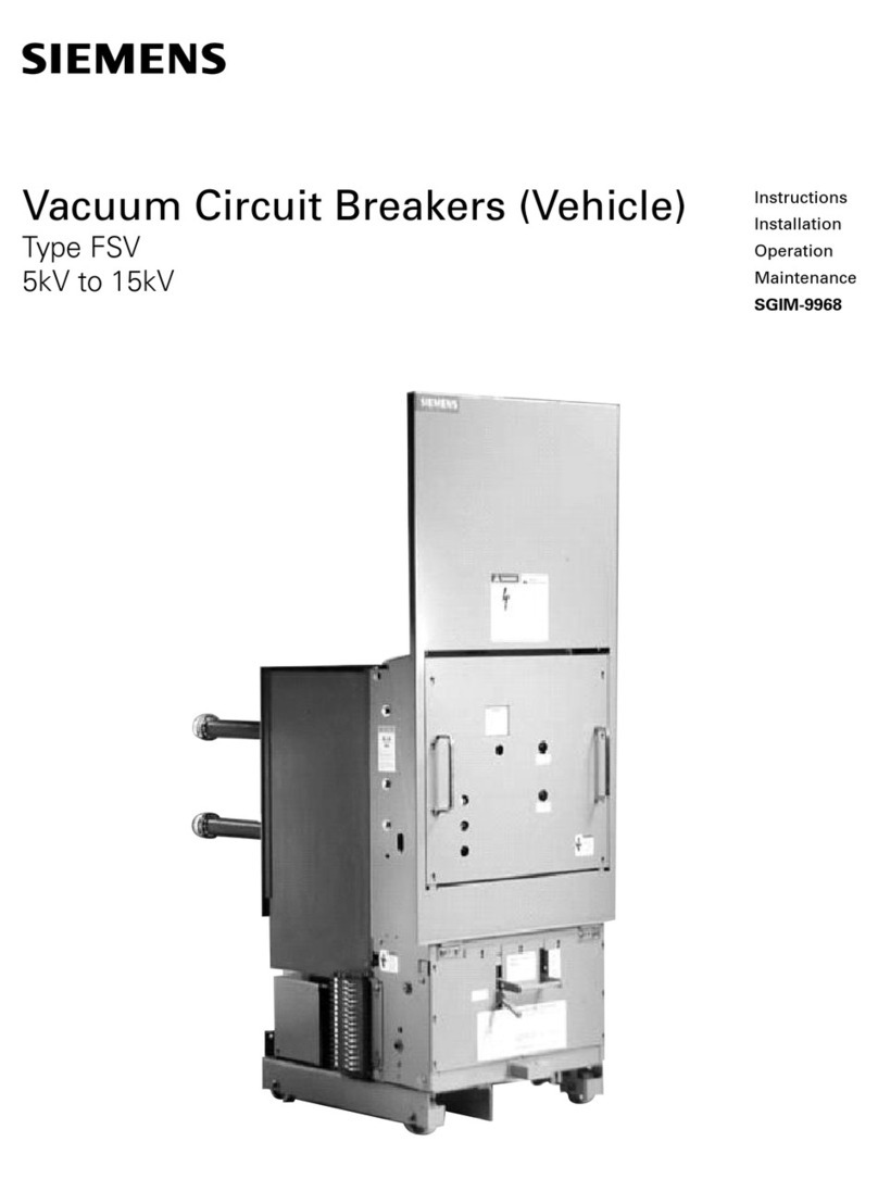
SIEMENS
Instruction
Installation
Operation
Maintenance
5
kV
and
15
kV
Vacuum
Circuit
Breakers
Type
GMI
SG
-
3268
-
02
-
o
3
/
o
-
/
Z
Courtesy of NationalSwitchgear.com
A
DANGER
h
Hazardous
voltages
.
Will
cause
death
,
serious
personal
injury
or
equipment
damage
.
Always
de
-
energize
and
ground
the
equipment
before
maintenance
.
Maintenance
should
be
performed
only
by
qualified
personnel
.
The
use
of
unauthorized
parts
in
the
repair
of
the
equipment
or
tampering
by
unqualified
personnel
will
result
in
dangerous
conditions
which
will
cause
severe
personal
injury
or
equipment
damage
.
Follow
all
safety
instructions
contained
herein
.
IMPORTANT
The
information
contained
herein
is
general
in
nature
and
not
intended
for
specific
application
purposes
.
It
does
not
relieve
the
user
of
responsibility
to
use
sound
practices
in
application
,
installation
,
operation
,
and
maintenance
of
the
equipment
purchased
.
Siemens
reserves
the
right
to
make
changes
in
the
specifications
shown
herein
or
to
make
improvements
at
any
time
without
notice
or
obligations
.
Should
a
conflict
arise
between
the
general
information
contained
in
this
publication
and
the
contents
of
drawings
or
supplementary
material
or
both
,
the
latter
shall
take
precedence
.
QUALIFIED
PERSON
For
the
purpose
of
this
manual
a
qualified
person
is
one
who
is
familiar
with
the
installation
,
construction
or
operation
of
the
equipment
and
the
hazards
involved
.
In
addition
,
this
person
has
the
following
qualifications
:
(
a
)
is
trained
and
authorized
to
de
-
energize
,
clear
,
ground
,
and
tag
circuits
and
equipment
in
accordance
with
established
safety
practices
.
(
b
)
is
trained
in
the
proper
care
and
use
of
protective
equipment
such
as
rubber
gloves
,
hard
hat
,
safety
glasses
or
face
shields
,
flash
clothing
,
etc
.
,
in
accordance
with
established
safety
practices
.
(
c
)
is
trained
in
rendering
first
aid
.
SUMMARY
These
instructions
do
not
purport
to
cover
all
details
or
variations
in
equipment
,
nor
to
provide
for
every
possible
contingency
to
be
met
in
connection
with
installation
,
operation
,
or
maintenance
.
Should
further
information
be
desired
or
should
particular
problems
arise
which
are
not
covered
sufficiently
for
the
purchaser
'
s
purposes
,
the
matter
should
be
referred
to
the
local
sales
office
,
listed
on
back
of
this
instruction
guide
.
The
contents
of
this
instruction
manual
shall
not
become
part
of
or
modify
any
prior
or
existing
agreement
commitment
or
relationship
.
The
sales
contract
contains
the
entire
obligation
of
Siemens
Energy
&
Automation
,
Inc
.
The
warranty
contained
in
the
contract
between
the
parties
is
the
sole
warranty
of
Siemens
Energy
&
Automation
,
Inc
.
Any
statements
contained
herein
do
not
create
new
warranties
or
modify
the
existing
warranty
.
i
Courtesy of NationalSwitchgear.com
Table
of
Contents
Introduction
and
Safety
Introduction
Qualified
Person
Signal
Words
Dangerous
Procedures
Field
Service
Operation
Receiving
,
Handling
and
Storage
Introduction
Receiving
Procedure
Shipping
Damage
Claims
Handling
Procedure
Storage
Procedure
Indoor
Storage
Outdoor
Storage
Space
Heating
Installation
Checks
and
Initial
Functional
Tests
Introduction
Inspections
,
Checks
and
Tests
without
Control
Power
De
-
Energizing
Control
Power
Spring
Discharge
Check
Removal
from
Lower
Cell
Removal
from
Upper
Cell
Removal
in
Outdoor
Non
-
Walk
in
Enclosures
Physical
Inspections
Manual
Spring
Charging
Check
As
-
Found
and
Vacuum
Check
Tests
Automatic
Spring
Charging
Check
Final
Mechanical
Inspect
'
ons
without
Control
Power
Interrupter
/
Operator
Description
Introduction
Vacuum
Interrupters
and
Primary
Disconnects
Primary
Disconnects
Phase
Barriers
Stored
Energy
Operating
Mechanism
Modes
of
Operation
-
Mid
-
1991
and
After
Modes
of
Operation
-
Discussion
Spring
Charging
Mode
Closing
Mode
Trip
Free
Mode
Opening
Mode
Rapid
Auto
-
Reclosing
Mode
Modes
of
Operation
-
Up
to
Mid
-
1991
Modes
of
Operation
-
Discussion
Spring
Charging
Mode
Closing
Mode
Trip
Free
Mode
Opening
Mode
Rapid
Auto
-
Reclosing
Mode
Closing
and
Opening
Springs
Trip
Free
Operation
Damper
Manual
Spring
Charging
Spring
Charging
Motor
Close
Solenoid
,
Trip
Solenoid
and
Anti
-
Pump
Relay
Secondary
Disconnect
Auxiliary
Switch
MOC
(
Mechanism
Operated
Cell
}
Switch
TOC
(
Truck
Operated
Cell
)
Switch
Limit
Switches
Standard
Schematic
Diagrams
Capacitor
Trip
Device
2
Undervoltage
Release
Interlocks
Trip
Free
Interlock
Rating
Interlock
Circuit
Breaker
Frame
Ground
Disconnect
Circuit
Breaker
Handling
Wheels
Racking
Mechanism
Maintenance
Introduction
and
Maintenance
Intervals
Recommended
Hand
Tools
Recommended
Maintenance
and
Lubrication
Removal
from
Switchgear
Checks
of
the
Primary
Power
Path
Cleanliness
Check
Inspection
of
Primary
Disconnects
Checks
of
the
Stored
Energy
Operator
Mechanism
Maintenance
and
Lubrication
Fastener
Check
Manual
Spring
Charging
and
Contact
Erosion
Checks
Damper
Assembly
Check
Electrical
Control
Checks
Check
of
the
Wiring
and
Terminals
Check
of
the
Secondary
Disconnect
Automatic
Spring
Charging
Check
Electrical
Close
and
Trip
Check
Checks
of
the
Spring
Charging
Motor
High
-
Potential
Tests
Vacuum
Integrity
Check
High
Potential
Test
Voltages
Vacuum
Integrity
Test
Procedure
As
-
Found
Insulation
and
Contact
Resistance
Tests
Insulation
and
Contact
Resistance
Test
Equipment
Insulation
and
Contact
Resistance
Test
Procedure
Inspection
and
Cleaning
of
Breaker
Insulation
Functional
Tests
Overhaul
Introduction
Circuit
Breaker
Overhaul
Replacement
at
Overhaul
Replacement
of
Closing
Springs
Replacement
of
Opening
Spring
Replacement
of
Closing
and
Tripping
Solenoids
Replacement
of
Anti
-
Pump
Relay
Replacement
of
the
Auxiliary
Switch
Replacement
of
Motor
Cut
-
Off
Switch
Replacement
of
Trip
Latch
Reset
Check
Switch
Replacement
of
LS
3
-
Mid
-
1991
and
After
Replacement
of
LS
3
-
Up
to
Mid
-
1991
Replacement
of
Spring
Dump
Switch
Replacement
of
Damper
Assembly
Replacement
of
Spring
Charging
Motor
Replacement
of
Primary
Disconnect
Fingers
Replacement
of
Vacuum
Interrupters
Preparation
Vacuum
Tube
Removal
Vacuum
Tube
Replacement
Periodic
Maintenance
and
Lubrication
Tasks
Troubleshooting
Appendix
19
2
19
2
20
2
20
2
20
2
20
20
3
3
20
21
-
26
3
3
21
3
21
3
21
3
21
22
3
3
22
4
-
7
22
4
23
4
23
23
4
4
23
4
24
5
24
6
24
6
24
6
24
6
25
6
25
7
25
8
-
20
25
25
8
8
25
9
25
9
25
25
9
10
26
10
26
27
-
35
10
27
11
27
11
27
11
11
27
27
12
28
12
12
28
12
28
13
28
28
13
28
13
29
14
14
30
30
14
30
14
15
30
15
31
31
15
31
16
32
16
36
16
37
17
39
17
17
1
Courtesy of NationalSwitchgear.com
1
Introduction
and
Safety
Signal
Words
The
signal
words
"
Danger
"
,
"
Warning
"
and
"
Caution
"
used
in
this
manual
indicate
the
degree
of
hazard
that
may
be
encoun
-
tered
by
the
user
,
These
words
are
defined
as
:
Danger
-
Indicates
an
imminently
hazardous
situation
which
,
if
not
avoided
,
will
result
in
death
or
serious
injury
.
Warning
-
Indicates
a
potentially
hazardous
situation
which
,
if
not
avoided
,
could
result
in
death
or
serious
injury
.
Caution
-
Indicates
a
potentially
hazardous
situation
which
,
if
not
avoided
,
may
result
in
minor
or
moderate
injury
.
Introduction
The
GMI
family
of
vacuum
circuit
breakers
is
designed
to
meet
all
the
applicable
ANSI
,
NEMAand
IEEE
standards
.
Success
-
ful
application
and
operation
of
this
equipment
depends
as
much
upon
proper
installation
and
maintenance
by
the
user
as
it
does
upon
the
careful
design
and
fabrication
by
Siemens
.
The
purpose
of
this
Instruction
Manual
is
to
assist
the
user
in
developing
safe
and
efficient
procedures
for
the
installation
,
maintenance
and
use
of
the
equipment
.
Contact
the
nearest
Siemens
representative
if
any
additional
information
is
desired
.
Dangerous
Procedures
In
addition
to
other
procedures
described
in
this
manual
as
dangerous
,
user
personnel
must
adhere
to
the
following
.
1
.
Always
work
on
a
de
-
energized
breaker
.
Always
de
-
ener
-
gize
a
breaker
,
and
remove
it
from
the
metal
-
clad
switchgear
before
performing
any
tests
,
maintenance
or
repair
.
2
.
Always
perform
maintenance
on
the
breaker
after
the
spring
-
charged
mechanisms
are
discharged
(
except
for
test
of
the
charging
mechanisms
)
,
3
.
Always
let
an
interlock
device
or
safety
mechanism
perform
its
function
without
forcing
or
defeating
the
device
.
ADANGER
Power
circuit
breakers
operate
at
high
voltages
and
have
spring
-
loaded
mechanical
parts
which
operate
at
high
speed
.
When
operated
improperly
,
this
equipment
will
cause
death
,
personal
injury
and
property
damage
.
To
avoid
elecTical
shock
,
burns
and
entanglement
in
moving
pals
this
equipment
must
be
installed
,
operated
and
maintained
only
by
qualified
persons
thoroughly
familiar
with
the
equipment
,
instruction
manuals
and
drawings
h
Field
Service
Operation
Siemens
can
provide
competent
,
well
-
trained
Field
Service
Representatives
to
provide
technical
guidance
and
advisory
assistance
for
the
installation
,
overhaul
,
repair
and
mainte
-
nance
of
S
emens
equipment
,
processes
and
systems
.
Con
-
tact
regional
service
centers
,
sales
offices
or
the
factory
for
details
.
Qualified
Person
For
the
purpose
of
this
manua
and
product
labels
,
a
"
Qualified
Person
"
is
one
who
is
familiar
with
the
installation
,
construction
and
operation
of
this
equipment
,
and
the
hazards
involved
.
In
addition
,
this
person
has
the
following
qualifications
:
•
Training
and
authorization
to
energize
,
de
-
energize
,
clear
,
ground
and
tag
circuits
and
equipment
in
accordance
with
established
safety
practices
.
•
Training
in
the
proper
care
and
use
of
protective
equipment
such
as
rubber
gloves
,
hare
hat
,
safety
glasses
,
face
shields
,
flash
clothing
,
etc
.
,
in
accordance
with
established
safety
procedures
.
•
Training
in
rendering
first
aid
,
2
Courtesy of NationalSwitchgear.com
Receiving
,
Handling
and
Storage
Introduction
Type
GMI
Vacuum
Interrupter
Circuit
Breakers
are
normally
installed
in
assembled
metal
-
clad
switchgear
,
and
the
Switch
-
gear
Instruction
Manual
(
SG
-
3258
)
contains
the
Receiving
,
Handling
and
Storage
instructions
for
assembled
metal
-
clad
switchgear
This
manual
covers
the
Receiving
,
Handling
and
Storage
instructions
for
Type
GMI
circuit
breakers
shipped
separately
from
the
switchgear
.
This
section
of
the
manual
is
intended
to
help
the
user
identify
,
inspect
and
protect
the
circuit
breaker
prior
to
its
installation
.
A
WARNING
Heavy
Weight
Can
cause
death
,
serious
injury
,
or
property
damage
.
Obtain
the
services
of
a
qualified
rigger
prior
to
hoisting
the
circuit
breaker
to
assure
adequate
safety
margins
in
the
hoisting
equipment
and
procedures
to
avoid
damage
Type
GMI
circuit
breakers
weigh
between
385
to
575
pounds
(
175
to
261
kg
)
.
See
Table
A
-
4
,
Technical
Data
in
Appendix
.
4
The
palleted
circuit
breaker
can
also
be
moved
using
a
properly
rated
fork
-
lift
vehicle
.
The
pallets
are
designed
for
movement
by
a
standard
fork
-
lift
vehicle
.
Storage
Procedure
1
.
Whenever
possible
,
install
circuit
breakers
in
their
assigned
switchgear
enclosures
for
storage
.
Follow
instructions
con
-
tained
in
the
Switchgear
Instruction
Manual
,
2
.
When
the
breaker
will
be
placed
on
its
pallet
for
storage
,
be
sure
the
unit
is
securely
bolted
to
the
pallet
and
covered
with
polyethylene
film
at
least
10
mils
thick
.
Indoor
Storage
-
Whenever
possible
,
store
the
circuit
breaker
indoors
.
The
storage
environment
must
be
clean
,
dry
and
free
of
such
items
as
construction
dust
,
corrosive
atmosphere
,
mechanical
abuse
and
rapid
temperature
variations
.
Outdoor
Storage
-
Outdoor
storage
is
not
recommended
.
When
no
other
option
is
available
,
the
circuit
breaker
must
be
completely
covered
and
protected
from
rain
,
snow
,
dirt
and
all
other
contaminants
.
Space
Heating
-
Space
heating
must
be
used
for
both
indoor
and
outdoor
storage
to
prevent
condensation
and
corrosion
.
When
stored
outdoors
,
between
150
to
200
watts
per
breaker
of
space
heating
is
recommended
.
If
the
circuit
breakers
are
stored
inside
the
switchgear
enclosures
,
and
the
switchgear
is
equipped
with
space
heaters
,
energize
the
space
heaters
.
Receiving
Procedure
Make
a
physical
inspection
of
the
shipping
container
before
removing
or
unpacking
the
circuit
breaker
.
Check
for
shipment
damage
or
indications
of
rough
handling
by
the
carrier
.
Check
each
item
against
the
manifest
to
identify
any
shortages
.
Accessories
such
as
the
manual
charging
lever
,
the
racking
crank
and
the
plug
jumper
are
shipped
separately
.
Shipping
Damage
Claims
(
When
Applicable
)
-
Follow
nor
-
mal
shipment
damage
procedures
,
which
should
include
:
1
.
Check
for
visible
damage
upon
arrival
.
2
.
Visible
damage
must
be
noted
on
delivery
receipt
,
and
acknowledged
with
driver
'
s
signature
,
Notation
,
"
Possible
internal
damage
,
subject
to
inspection
"
must
be
on
delivery
receipt
.
3
.
Notify
Siemens
Sales
office
immediately
of
any
shipment
damage
.
4
.
Arrange
for
carrier
s
inspection
.
Do
not
move
the
unit
from
its
unloading
point
.
Handling
Procedure
1
.
Carefully
remove
the
shipping
carton
from
the
circuit
breaker
.
Keep
the
shipping
pallet
for
later
use
if
the
breaker
is
to
be
stored
prior
to
its
installation
.
2
.
Inspect
for
concealed
damage
.
Notification
to
carrier
must
take
place
within
15
days
to
assure
prompt
resolution
of
claims
,
3
.
Each
circuit
breaker
should
be
appropriately
lifted
to
avoid
crushing
the
side
panels
of
the
breaker
,
or
damaging
the
primary
disconnect
subassemblies
.
3
Courtesy of NationalSwitchgear.com
Installation
Checks
and
Initial
Functional
Tests
Introduction
This
section
provides
a
description
of
the
inspections
,
checks
and
tests
to
be
performed
on
the
circuit
breaker
prior
to
operation
in
the
metal
-
clad
switchgear
.
ADANGER
h
Hazardous
voltages
and
high
-
speed
mechanical
parts
.
Will
cause
death
,
severe
personal
injury
,
or
property
damage
.
Read
instruction
manuals
,
observe
safety
instructions
and
use
qualified
personnel
.
Inspections
,
Checks
and
Tests
without
Control
Power
Vacuum
circuit
breakers
are
normally
shipped
with
their
pri
-
mary
contacts
open
and
their
springs
discharged
.
However
,
it
is
critical
to
f
/
rsfverify
the
discharged
condition
of
the
spring
-
loaded
mechanisms
after
de
-
energizing
control
power
.
De
-
Energizing
Control
Power
in
Switchgear
-
When
the
circuit
breaker
is
mounted
in
switchgear
,
open
the
control
power
disconnect
device
in
the
metal
-
clad
switchgear
cubicle
.
Figure
1
shows
the
location
of
this
disconnect
in
a
standard
GM
switchgear
assembly
.
The
control
power
disconnect
device
is
located
on
the
device
panel
above
the
lower
circuit
breaker
and
below
the
upper
circuit
breaker
.
Figure
1
shows
a
pullout
type
fuse
holder
.
Removal
of
the
fuse
holder
de
-
energizes
control
power
to
the
circuit
breaker
in
the
respective
switchgear
cell
.
In
some
switchgear
assemblies
,
a
molded
case
circuit
breaker
is
used
in
lieu
of
the
pull
out
type
fuse
holder
.
Opening
this
circuit
breaker
accomplishes
the
same
result
:
control
power
is
dis
-
connected
.
Spring
Discharge
Check
(
Figure
2
)
-
Perform
the
Spring
Discharge
Check
before
removing
the
circuit
breaker
from
the
pallet
or
removing
it
from
the
switchgear
.
The
spring
discharge
check
consists
of
simply
performing
the
following
tasks
in
the
order
given
.
This
check
assures
that
both
the
tripping
and
closing
springs
are
fully
discharged
.
1
.
Press
red
Trip
pushbutton
.
2
.
Press
black
Close
pushbutton
.
3
.
Again
press
red
Trip
pushbutton
.
4
.
Verify
Spring
Condition
Indicator
shows
DISCHARGED
.
5
.
Verify
Main
Contact
Status
Indicator
shows
OPEN
.
Removal
from
Lower
Cell
in
Indoor
(
if
not
on
raised
pad
)
and
Shelter
-
Clad
Outdoor
Switchgear
-
After
performing
the
Spring
Discharge
Check
(
with
control
power
de
-
energized
)
,
remove
the
circuit
breaker
from
its
switchgear
cubicle
.
1
.
Insert
the
racking
crank
on
the
racking
screw
on
the
front
of
the
breaker
cell
,
and
push
in
.
This
action
operates
the
racking
interlock
latch
.
Figure
3
shows
racking
of
a
circuit
breaker
in
the
upper
cell
-
the
process
is
similar
for
a
breaker
in
the
lower
cell
.
2
.
Rotate
the
racking
crank
counterclockwise
until
the
breaker
is
in
the
Disconnect
position
.
If
the
racking
crank
is
not
of
the
"
Captive
"
type
,
constant
inward
pressure
is
required
during
racking
to
maintain
engagement
with
the
racking
mecha
-
nism
.
3
.
Move
the
breaker
release
latch
to
the
left
and
pull
the
circuit
breaker
out
from
the
Disconnect
position
.
The
breaker
can
now
be
removed
from
cubicle
.
Figure
1
:
Control
Power
Disconnects
in
Switchgear
.
Figure
2
:
Front
Panel
of
GMI
Circuit
Breaker
.
4
Courtesy of NationalSwitchgear.com
Installation
Checks
and
Initial
Functional
Tests
The
procedure
for
removal
of
an
upper
circuit
breaker
is
:
1
.
Insert
the
two
extension
rails
into
the
fixed
rails
.
Be
sure
the
extension
rails
are
properly
secured
in
place
.
(
This
can
be
done
at
Step
4
if
preferred
.
)
2
.
Insert
the
racking
crank
on
the
racking
screw
on
the
front
of
the
breaker
cell
,
and
push
in
.
This
action
operates
the
racking
interlock
latch
.
Figure
3
shows
racking
of
a
circuit
breaker
in
the
upper
cell
.
3
.
Rotate
the
racking
crank
counterclockwise
until
the
breaker
is
in
the
Disconnect
position
.
If
the
racking
crank
is
not
of
the
"
Captive
"
type
,
constant
pressure
is
required
during
racking
to
maintain
engagement
with
the
racking
mechanism
.
4
.
If
you
have
not
yet
installed
the
extension
rails
,
do
so
now
.
Note
that
some
difficulty
may
be
experienced
installing
the
extension
rails
if
the
circuit
breaker
is
in
the
Disconnect
position
.
If
difficulty
is
encountered
,
rack
the
circuit
breaker
to
the
Test
position
,
install
the
extension
rails
,
and
then
rack
the
circuit
breaker
to
the
Disconnect
position
.
4
.
The
circuit
breaker
is
now
free
to
be
rolled
out
on
the
floor
using
the
handles
as
shown
in
Figure
4
.
The
wheels
of
the
circuit
breaker
are
virtually
at
floor
level
(
unless
the
switch
-
gear
is
installed
on
a
raised
pad
)
,
and
one
person
can
easily
handle
the
unit
.
Removal
from
Upper
Cell
(
Indoor
and
Shelter
-
Clad
Out
-
door
Switchgear
)
-
Removal
of
the
upper
breaker
in
a
two
-
high
assembly
is
similar
to
removal
of
a
breaker
from
a
lower
cell
,
with
several
additional
steps
.
Figure
5
shows
one
of
the
two
breaker
extension
rails
being
inserted
into
the
fixed
rails
within
the
upper
cell
of
two
-
high
switchgear
equipment
.
The
rails
engage
locking
pins
in
the
fixed
rails
to
secure
them
in
position
.
AWARNING
Heavy
Weight
Can
cause
death
,
serious
injury
,
or
property
damage
.
Always
use
extension
rails
to
remove
or
install
circuit
breaker
in
the
upper
cell
or
in
cells
not
installed
at
floor
level
.
5
.
Move
the
breaker
release
latch
to
the
left
and
pull
the
circuit
breaker
out
from
the
Disconnect
position
.
The
breaker
is
now
free
to
be
rolled
out
on
the
two
extension
rails
using
the
handles
on
the
front
of
the
circuit
breaker
.
6
.
Remove
the
breaker
from
the
two
extension
rails
using
the
approved
Siemens
breaker
lifting
device
.
7
.
Lift
the
two
extension
rails
and
withdraw
them
from
the
switchgear
.
Figure
3
:
Racking
Circuit
Breaker
in
Switchgear
.
Figure
5
:
Use
of
Extension
Rails
for
Upper
Compartment
.
Figure
4
:
Removal
of
Circuit
Breaker
.
5
Courtesy of NationalSwitchgear.com
Installation
Checks
and
Initial
Functional
Tests
As
-
Found
and
Vacuum
Check
Tests
-
Perform
and
record
the
results
of
both
the
As
-
Found
insulation
test
and
the
vacuum
check
high
-
potential
test
.
Procedures
for
these
tests
are
described
in
the
Maintenance
Section
of
this
manual
.
Removal
from
Upper
and
Lower
Cell
in
Outdoor
Non
-
Walk
In
Enclosures
or
for
Indoor
Switchgear
Installed
on
a
Raised
Pad
-
Because
the
floor
level
in
non
-
walk
in
outdoor
enclosures
is
approximately
6
inches
above
grade
(
founda
-
tion
)
level
,
the
lower
breaker
in
either
a
one
-
high
or
two
-
high
section
of
switchgear
must
be
removed
using
the
preceding
procedure
for
upper
breaker
removal
.
The
approved
breaker
lifting
device
should
be
used
for
re
-
moval
of
both
lower
and
upper
breakers
from
the
extension
rails
of
outdoor
non
-
walk
in
enclosures
.
Physical
Inspections
1
.
Verify
that
rating
of
the
circuit
breaker
is
compatible
with
both
the
system
and
the
switchgear
.
2
.
Perform
a
visual
shipping
damage
check
.
Clean
the
breaker
of
all
shipping
dust
,
dirt
and
foreign
material
.
Manual
Spring
Charging
Check
1
.
Insert
the
manual
spring
charging
lever
into
the
manual
charge
handle
socket
as
shown
in
Figure
6
.
Operate
the
lever
up
and
down
until
the
spring
condition
indicator
shows
the
closing
spring
is
Charged
.
2
.
Repeat
the
Spring
Discharge
Check
.
3
.
Verify
that
the
springs
are
discharged
and
the
breaker
primary
contacts
are
open
by
indicator
positions
.
Automatic
Spring
Charging
Check
Note
:
A
temporary
source
of
control
power
and
test
leads
may
be
required
if
the
control
power
source
has
not
been
con
-
nected
to
the
switchgear
.
(
Refer
to
the
specific
wiring
informa
-
tion
and
rating
label
for
your
circuit
breaker
to
determine
the
voltage
required
and
where
the
control
voltage
signal
should
be
applied
.
Usually
,
spring
charging
power
is
connected
to
secondary
disconnect
fingers
SD
16
and
SD
15
,
closing
control
power
to
SD
13
and
SD
15
,
and
tripping
power
to
SD
1
and
SD
2
.
)
When
control
power
is
connected
to
the
GMI
circuit
breaker
,
the
closing
springs
should
automatically
charge
.
The
automatic
spring
charging
features
of
the
circuit
breaker
must
be
checked
.
Control
power
is
required
for
automatic
spring
charging
to
take
place
.
1
.
Open
control
power
circuit
by
removing
pullout
fuse
holder
shown
in
Figure
1
,
2
.
Install
breaker
end
of
split
plug
jumper
(
if
furnished
)
shown
in
Figure
7
to
the
circuit
breaker
.
The
plug
jumper
is
secured
by
means
of
screws
,
over
the
circuit
breaker
'
s
secondary
contacts
.
A
CAUTIO
4
5
=
=
asns
»
21659
-
93
Figure
7
:
Split
Plug
Jumper
Connected
to
Circuit
Breaker
.
Figure
6
:
Manual
Charging
of
Closing
Springs
.
6
Courtesy of NationalSwitchgear.com
Installation
Checks
and
Initial
Functional
Tests
3
.
Install
the
switchgear
end
of
the
plug
jumper
shown
in
Figure
8
to
the
secondary
disconnect
block
inside
the
switchgear
cubicle
.
The
jumper
slides
into
place
.
The
plug
jumper
interconnects
all
control
power
and
signal
leads
(
e
.
g
.
,
remote
trip
and
close
contacts
)
between
the
switch
-
gear
and
the
circuit
breaker
.
4
.
Energize
(
close
)
the
control
power
circuit
disconnect
(
Fig
-
ure
1
)
.
5
.
Use
the
Close
and
Trip
controls
(
Figure
2
)
to
first
Close
and
then
Open
the
circuit
breaker
contacts
.
Verify
contact
positions
visually
by
observing
the
Open
/
Closed
indicator
on
the
circuit
breaker
.
6
.
De
-
energize
control
power
by
repeating
Step
1
.
Disconnect
the
plug
jumper
from
the
switchgear
first
and
next
from
the
circuit
breaker
.
7
.
Perform
the
Spring
Discharge
Check
again
.
Verify
that
the
closing
springs
are
discharged
and
the
primary
contacts
of
the
GMI
circuit
breaker
are
open
.
Final
Mechanical
Inspections
without
Control
Power
1
.
Make
a
final
mechanical
inspection
of
the
circuit
breaker
.
Verify
that
the
contacts
are
in
the
Open
position
,
and
the
closing
springs
are
Discharged
.
2
.
Check
the
upper
and
lower
primary
studs
and
contact
fingers
shown
in
Figure
9
.
Verify
mechanical
condition
of
finger
springs
and
the
disconnect
studs
.
3
.
Coat
movable
primary
contact
fingers
(
Figure
9
)
and
the
secondary
disconnect
contacts
(
Figure
9
and
22
)
with
a
light
film
of
Siemens
Contact
Lubricant
No
.
15
-
171
-
370
-
002
.
4
.
The
GMI
vacuum
circuit
breaker
is
ready
for
installation
into
its
assigned
cubicle
of
the
metal
-
clad
switchgear
.
Refer
to
removal
procedures
and
re
-
install
the
circuit
breaker
into
the
switchgear
.
5
.
Refer
to
the
Switchgear
Instruction
Manual
for
functional
tests
of
an
installed
circuit
breaker
.
Figure
9
:
Rear
of
GMI
Breaker
with
Primary
Disconnects
.
Figure
8
:
Split
Plug
Jumper
Connected
to
Switchgear
.
7
Courtesy of NationalSwitchgear.com
Interrupter
/
Operator
Description
Vacuum
Interrupters
and
Primary
Disconnects
The
operating
principle
of
the
GMI
vacuum
interrupter
is
simple
.
Figure
11
is
a
cutaway
view
of
a
typical
vacuum
interrupter
.
The
entire
assembly
is
sealed
after
a
vacuum
is
established
.
The
interrupter
stationary
contact
is
connected
to
the
upper
disconnect
stud
of
the
circuit
breaker
.
The
inter
-
rupter
movable
contact
is
connected
to
the
lower
disconnect
stud
and
driving
mechanism
of
the
circuit
breaker
.
The
metal
bellows
assembly
provides
a
secure
seal
around
the
movable
contact
,
preventing
loss
of
vacuum
while
permitting
vertical
motion
of
the
movable
contact
.
Introduction
The
Type
GMI
vacuum
circuit
breaker
is
of
drawout
construc
-
tion
designed
for
use
in
medium
voltage
,
metal
-
clad
switch
-
gear
.
The
GMI
circuit
breaker
conforms
to
the
requirements
of
ANSI
standards
C
37.20
.
2
,
C
37.04
,
C
37.06
,
C
37.09
and
C
37.010
.
GMI
circuit
breakers
consist
of
three
vacuum
interrupters
,
a
stored
energy
operating
mechanism
,
necessary
electrical
controls
and
interlock
devices
,
disconnect
devices
to
connect
the
breaker
to
both
primary
and
control
power
and
an
operator
housing
.
On
some
circuit
breaker
ratings
insulating
barriers
are
located
between
the
vacuum
interrupters
or
along
the
sides
.
This
section
describes
the
operation
of
each
major
subassem
-
bly
as
an
aid
in
the
operation
,
installation
,
maintenance
and
repair
of
the
GMI
vacuum
circuit
breaker
.
FIXED
CONTACT
CURRENT
CONNECTION
7
7
g
'
A
7
g
CERAMIC
INSULATOR
g
'
4
7
/
7
g
A
7
%
'
A
A
g
A
l
A
A
7
ARC
CHAMBER
A
2
%
A
A
%
A
7
p
7
'
n
%
ARC
SHIELD
r
%
\
w
\\
rr
y
v
y
Vi
%
N
im
FIXED
CONTACT
m
%
MOVING
CONTACT
•
-
-
-
'
.
T
r
g
%
d
CERAMIC
INSULATOR
g
g
-
2
7
,
g
2
2
2
g
2
METAL
BELLOWS
g
i
_
r
7
,
g
g
a
?
GUIDE
—
MOVING
CONTACT
CURRENT
CONNECTION
mu
Figure
11
:
Cutaway
View
of
GMI
Vacuum
Interrupters
.
When
the
two
contacts
separate
an
arc
is
initiated
which
continues
conduction
up
to
the
following
current
zero
.
At
current
zero
,
the
arc
extinguishes
and
any
conductive
metal
vapor
which
has
been
created
by
and
supported
the
arc
condenses
on
the
contacts
and
on
the
surrounding
vapor
shield
.
Contact
materials
and
configuration
are
optimized
to
achieve
arc
motion
and
to
minimize
switching
disturbances
.
Figure
10
:
Front
View
of
GMI
Breaker
.
8
Courtesy of NationalSwitchgear.com
Interrupter
/
Operator
Description
Primary
Disconnects
-
Figure
12
is
a
side
view
of
the
circuit
breaker
with
a
side
phase
barrier
removed
to
show
details
of
the
primary
disconnects
.
Each
circuit
breaker
has
three
upper
and
three
lower
primary
disconnects
.
Upper
primary
discon
-
nects
are
connected
to
the
stationary
contacts
of
the
vacuum
interrupters
,
and
the
lower
primary
disconnects
to
the
movable
contacts
.
Each
disconnect
arm
has
a
set
of
multiple
spring
loaded
fingers
that
mate
with
bus
bars
in
the
metal
-
clad
switchgear
.
The
number
of
fingers
in
the
disconnect
assembly
varies
with
the
continuous
and
/
or
momentary
rating
of
the
circuit
breaker
.
There
are
three
insulating
push
rods
.
Each
push
rod
connects
the
movable
contact
of
one
of
the
vacuum
interrupters
to
the
jack
shaft
driven
by
the
closing
and
tripping
mechanism
.
Flexible
connectors
ensure
secure
electrical
connections
be
-
tween
the
movable
contacts
of
each
interrupter
and
its
bottom
primary
disconnect
.
Phase
Barriers
-
Phase
barrier
configurations
vary
among
GMI
breakers
depending
on
voltage
and
continuous
current
ratings
.
Figure
13
is
a
rear
view
of
a
circuit
breaker
that
shows
the
two
outer
(
phase
to
ground
)
insulating
barriers
and
two
interphase
barriers
.
The
interphase
barriers
are
not
provided
on
all
circuit
breaker
ratings
.
These
four
plates
of
glass
polyester
insulating
material
are
attached
to
the
circuit
breaker
and
provide
suit
-
able
electrical
insulation
between
the
vacuum
interrupter
pri
-
mary
circuits
and
the
housing
.
Stored
Energy
Operating
Mechanism
The
stored
energy
operating
mechanism
of
the
GMI
circuit
breaker
is
an
integrated
arrangement
of
springs
,
solenoids
and
mechanical
devices
designed
to
provide
a
number
of
critical
functions
.
The
energy
necessary
to
close
and
open
the
contacts
of
the
vacuum
interrupters
is
stored
in
powerful
tripping
and
closing
springs
.
These
springs
are
normally
charged
automatically
,
but
there
are
provisions
for
manual
charging
.
The
operating
mechanism
that
controls
charging
,
closing
and
tripping
functions
is
fully
trip
-
free
,
i
.
e
.
,
spring
charging
does
not
automatically
change
the
position
of
the
primary
contacts
,
and
the
closing
function
may
be
overridden
by
the
tripping
function
at
any
time
.
Note
:
Two
different
latch
systems
have
been
used
in
GMI
circuit
breakers
,
with
changeover
from
one
design
to
the
other
occurring
in
mid
-
1991
.
This
instruction
manual
describes
both
designs
.
Pages
10
-
11
describe
the
operation
of
the
mechanism
used
beginning
in
approximately
mid
-
1991
.
Pages
12
-
13
describe
the
operation
of
the
mechanism
used
from
1989
until
approximately
mid
-
1991
.
f
BJ
**
;
j
|
;
;
v
>
..
.
.
tfvirnnv
Figure
12
:
Upper
and
Lower
Primary
Disconnects
.
Figure
13
:
Breaker
with
Interphase
and
Outerphase
Barriers
.
9
Courtesy of NationalSwitchgear.com
Interrupter
/
Operator
Description
!
©
TRIP
—
-
SOLENOID
©
TRIP
—
.
SOLENOID
TRIP
SOLENOID
ARMATURE
CrP
266
TRIP
SOLENOID
ARMATURE
266
3
BANANA
BANANA
LINK
LINK
o
113
113
T
DRIVE
CAM
'
TRIP
ACTUATOR
TRIP
ACTUATOR
20
C
DRIVE
i
152
O
152
CAM
o
o
20
o
•
L
-
LATCH
FACE
CLOSE
-
HATCHET
-
f
?
i
'
(
r
TRIP
SHAFT
n
TRIP
SHAFT
CAM
—
FOLLOWER
79
/
CAM
79
©
v
;
FOLLOWER
ROLLER
/
115
115
-
TRIP
HATCHET
\
o
-
TRIP
HATCHET
99
A
O
©
99
JACK
SHAFT
MAIN
o
:
JACK
SHAFT
MAIN
LINK
LINK
217
120
120
217
POINT
"
A
"
POINT
"
A
"
o
©
JACK
SHAFT
PLATE
O
JACK
SHAFT
PLATE
nju
Figure
15
a
:
Breaker
Open
—
Closing
Springs
Charged
.
Figure
14
a
:
Breaker
Open
—
Closing
Springs
Discharged
.
Figure
16
a
shows
the
ratchet
wheel
(
15
)
which
is
free
to
rotate
about
the
main
cam
shaft
(
3
)
.
The
ratchet
wheel
is
driven
by
either
the
charging
motor
or
the
manual
charge
handle
socket
(
52
)
.
When
the
springs
are
charged
electrically
,
the
motor
eccentric
(
100
)
introduces
a
rocking
motion
into
the
drive
plate
(
13
)
.
As
this
piate
rocks
back
and
forth
,
the
lower
pawl
(
24
-
1
)
(
which
is
connected
to
the
drive
plate
)
imparts
counterclock
-
wise
rotation
of
the
ratchet
wheel
(
15
)
,
one
tooth
at
a
time
.
The
upper
pawl
(
24
-
2
)
acts
as
a
holding
pawl
during
electrical
charging
.
When
the
springs
are
charged
manually
,
up
and
down
pump
-
ing
action
of
the
spring
charging
handle
in
the
manual
charge
handle
socket
(
52
)
causes
the
pawl
plate
(
11
)
to
rock
back
and
forth
through
the
movement
of
the
manual
charging
link
(
48
)
.
The
upper
pawl
(
24
-
2
)
drives
the
ratchet
plate
counterclock
-
wise
during
manual
charging
,
and
the
lower
pawl
(
24
-
1
)
becomes
the
holding
device
.
At
the
beginning
of
thecharging
cycle
,
ratchet
pin
(
16
)
is
atthe
6
o
'
clock
position
.
The
ratchet
pin
is
connected
to
the
ratchet
wheel
.
Upon
being
advanced
by
ratchet
action
to
the
12
o
'
clock
position
,
this
pin
engages
the
drive
arms
(
8
)
which
are
keyed
to
the
main
cam
shaft
.
Consequently
,
counterclockwise
rotation
of
the
ratchet
wheel
causes
the
ratchet
pin
to
drive
the
main
cam
shaft
counterclockwise
,
When
the
ratchet
pin
reacnes
the
6
o
'
clock
position
,
the
closing
springs
are
fully
charged
.
Driving
pawl
(
24
-
1
)
is
disengaged
,
the
spring
condition
indicator
cam
(
18
)
has
rotated
allowing
the
spring
charged
flag
(
132
)
to
drop
into
the
lower
(
charged
)
position
,
which
also
operates
the
motor
cutoff
switch
(
LS
1
)
and
spring
charged
switch
(
LS
2
)
(
258
)
(
see
Figures
17
a
and
27
)
.
The
closing
springs
are
restrained
fully
charged
by
close
hatchet
(
22
)
against
close
shaft
(
72
)
.
Modes
of
Operation
-
Mid
-
1991
and
After
Pages
10
-
11
describe
the
operation
of
the
mechanism
used
beginning
in
approximately
mid
-
1991
.
This
mechanism
can
be
identified
by
observing
the
close
latch
above
the
spring
charging
motor
on
the
left
side
of
the
circuit
breaker
.
Refer
to
Figure
18
a
.
The
close
latch
is
installed
on
the
close
shaft
assembly
72
,
and
includes
a
hardened
latch
face
.
This
face
contacts
a
bearing
which
is
part
of
the
close
hatchet
assembly
105
.
If
the
mechanism
has
a
close
hatchet
which
bears
directly
on
the
close
shaft
,
referto
pages
12
-
13
for
the
description
of
your
mechanism
.
Modes
of
Operation
-
Discussion
Some
maintenance
procedures
are
more
easily
understood
when
the
operating
mechanism
modes
of
operation
are
de
-
scribed
in
detail
.
The
next
few
paragraphs
explain
the
five
modes
or
status
conditions
(
charging
,
closing
,
trip
-
free
,
open
-
ing
and
rapid
auto
-
reclosing
)
of
the
stored
energy
operating
mechanism
.
Note
:
All
discussion
of
modes
of
operation
assumes
that
the
reader
is
viewing
the
operator
from
the
front
,
or
from
the
right
hand
side
.
Spring
Charging
Mode
-
Figures
14
a
and
15
a
show
several
key
components
of
the
operator
mechanism
in
positions
cor
-
responding
to
the
breaker
open
,
with
the
closing
springs
discharged
(
Figure
14
a
)
and
charged
(
Figure
15
a
)
.
Figure
16
a
shows
portions
of
the
operator
mechanism
that
manually
or
electrically
charge
the
closing
springs
.
The
drive
cam
(
20
)
,
the
closing
spring
crank
arms
(
Figure
19
)
and
spring
condition
indicator
cam
(
18
)
are
directly
keyed
to
the
main
cam
shaft
(
3
)
.
The
main
cam
shaft
rotates
counterclockwise
.
The
closing
springs
are
attached
to
the
crank
arms
,
and
are
extended
during
the
charging
cycle
.
10
Courtesy of NationalSwitchgear.com
Interrupter
/
Operator
Description
PAWL
PLATE
MOTOR
CUTOFF
SPRING
CHARGED
SWITCHES
(
LS
1
/
LS
2
)
11
©
SOLENOID
\
©
S
V
365
-
MANUAL
CHARGING
LINK
MANUAL
-
CHARGE
HANDLE
SOCKET
j
258
48
CLOSE
SHAFT
ACTUATOR
O
CHARGED
SPRING
FLAG
52
75
132
UPPER
PAWL
CLOSE
C
CLOSE
SHAFT
SHAFT
©
24
-
2
72
72
DRIVE
\
cm
\
RATCHET
WHEEL
20
MAIN
CAMSHAFT
SPRING
-
CONDITION
INDICATOR
15
MAIN
CAM
SHAFT
DRIVE
3
CAM
ARM
\
18
8
\
RATCHET
JACK
SHAFT
PIN
LOWER
PAWL
16
217
MAIN
24
-
1
CAM
JACK
SHAFT
PLATE
217
-
3
i
CHARGING
MOTOR
ECCENTRIC
i
p
RXLOWER
115
O
i
n
-
i
POINT
"
A
"
DRIVE
PLATE
^
13
J
Figure
16
a
:
Pawl
and
Ratchet
Drive
.
Figure
17
a
:
Closing
Mode
Closing
Mode
(
Figure
17
a
)
-
Energizing
the
close
solenoid
(
265
)
pulls
the
solenoid
armature
against
the
closing
shaft
actuator
(
75
)
and
causes
the
close
shaft
(
72
)
to
rotate
approxi
-
mately
15
°
If
the
closing
springs
are
charged
,
the
close
hatchet
(
22
)
will
be
released
by
this
rotation
allowing
the
main
cam
shaft
(
3
)
to
be
driven
by
the
closing
springs
Depressing
the
manual
close
button
on
the
operator
panel
causes
the
rotation
of
the
close
shaft
(
72
)
by
the
lower
end
of
the
close
shaft
actuator
(
75
)
.
Rotation
of
the
main
cam
shaft
(
3
)
in
a
manual
closing
operation
is
identical
to
that
of
an
electrical
closing
operation
.
As
the
main
cam
shaft
(
3
)
rotates
,
the
cam
follower
(
115
)
is
driven
by
drive
cam
(
20
)
,
and
the
main
link
(
120
)
is
forced
outwards
,
and
rotation
of
the
jackshaft
assem
-
bly
(
217
)
occurs
.
There
are
three
drive
links
attached
to
Point
"
A
"
of
each
of
the
three
jack
shaft
drive
plates
.
Each
drive
link
is
connected
to
the
movable
contact
of
one
vacuum
inter
-
rupter
.
Closing
rotation
(
counterclockwise
)
of
the
jack
shaft
assembly
closes
the
contacts
of
the
three
vacuum
interrupters
.
During
closing
operation
,
rotation
of
jack
shaft
assembly
(
217
)
forces
the
opening
(
i
.
e
.
,
tripping
)
spring
into
its
charged
position
,
Trip
Free
Mode
-
If
at
any
time
during
breaker
closing
,
the
trip
shaft
(
79
)
(
Figure
14
a
)
operates
as
a
result
of
either
an
electrical
or
mechanical
trip
,
trip
hatchet
(
99
)
is
free
to
rotate
.
When
the
trip
hatchet
(
99
)
rotates
,
cam
follower
(
115
)
is
displaced
by
drive
cam
(
20
)
without
motion
of
the
jack
shaft
(
217
)
.
Mechanical
trip
free
operation
is
provided
by
manual
tripping
,
electrical
tripping
and
/
or
the
mechanical
interlocks
.
Opening
Mode
-
Opening
or
tripping
the
vacuum
interrupter
contacts
is
accomplished
by
rotation
of
the
trip
shaft
(
79
)
.
Rotation
may
be
produced
either
electrically
,
by
energizing
the
trip
solenoid
(
266
)
(
Figure
15
a
)
,
or
manually
by
pressing
the
trip
button
.
Energizing
the
trip
solenoid
causes
the
upper
arm
of
the
trip
actuator
(
152
)
to
rotate
counterclockwise
.
Pressing
the
trip
button
causes
the
trip
actuator
lower
arm
to
move
,
again
producing
rotation
of
the
trip
shaft
.
All
of
the
linkages
are
trip
free
,
and
tripping
or
opening
is
unaffected
by
charging
status
of
the
closing
springs
or
position
of
the
drive
cam
(
20
)
.
Rapid
Auto
-
Reclosing
Mode
(
Optional
)
-
The
closing
springs
are
automatically
recharged
by
the
motor
driven
operating
mechanism
when
the
breaker
has
closed
.
The
operating
mechanism
is
capable
of
the
open
-
close
-
open
duty
cycle
required
for
rapid
auto
-
reclosing
.
Atrip
latch
check
switch
and
a
relay
(
delay
on
dropout
)
prevent
release
of
the
closing
spring
energy
if
the
trip
hatchet
(
99
)
is
not
in
its
reset
position
.
This
ensures
the
mechanism
does
not
operate
trip
free
on
an
instantaneous
reclosure
.
CLOSE
SHAFT
ASSEMBLY
CLOSE
SHAFT
72
CLOSE
LATCH
CLOSE
HATCHET
CLOSE
HATCHE
ASSEMBLY
105
*
—
FRONT
MAIN
CAM
SHAFT
FRONT
—
3
7
T
<
d
I
\
\
'
,
<
Z
>
)
i
®
)
I
II
I
\
SPRING
CHARGING
/
MOTOR
/
SPRING
CHARGING
MOTOR
2
>
d
—
,
.
I
=
Ln
n
Mechanism
-
Mid
-
1991
and
After
(
Viewed
from
Left
Side
)
(
Refer
to
Pages
10
-
11
)
Mechanism
-
Up
to
Mid
-
1991
(
Viewed
form
Left
Side
)
(
Refer
to
Pages
12
-
13
)
Figure
18
a
:
Identification
of
Mechanism
Vintage
11
Courtesy of NationalSwitchgear.com
Interrupter
/
Operator
Description
Trip
Trip
O
o
Solenoid
Solenoid
0
°
©
266
266
Trip
Solenoid
Armature
Drive
Cam
o
o
Trip
Solenoid
Armature
o
o
20
O
O
Trip
o
o
Actuator
Trip
152
Actuator
Banana
152
Link
O
Trip
O
113
Hatchet
O
Drive
Cam
99
©
20
Trip
Banana
“
"
Link
Cam
Follower
Shaft
o
79
113
115
Close
Hatchet
Trip
Main
Main
Hatchet
22
Link
Link
99
120
120
Jack
Shaft
Jack
217
Jack
Shaft
Plate
©
Shaft
O
O
Point
"
A
'
f
[
217
n
Figure
15
b
:
Breaker
Open
—
Closing
Springs
Charged
.
Figure
14
b
:
Breaker
Open
—
Closing
Springs
Discharged
.
either
the
charging
motor
or
the
manual
charge
handle
socket
(
52
)
.
When
the
springs
are
charged
electrically
,
the
motor
eccentric
(
100
)
introduces
a
rocking
motion
into
the
drive
plate
(
13
)
.
As
this
plate
rocks
back
and
forth
,
the
lower
pawl
(
24
-
1
)
(
which
is
connected
to
the
drive
plate
)
imparts
counterclock
-
wise
rotation
of
the
ratchet
wheel
(
15
)
,
one
tooth
at
a
time
.
The
upper
pawl
(
24
-
2
)
acts
as
a
holding
pawl
during
electrical
charging
.
When
the
springs
are
charged
manually
,
up
and
down
pump
-
ing
action
of
the
spring
charging
handle
in
the
manual
charge
handle
socket
(
52
)
causes
the
pawl
plate
(
11
)
to
rock
back
and
forth
through
the
movement
of
the
manual
charging
link
(
48
)
.
The
upper
pawl
(
24
-
2
)
drives
the
ratchet
plate
counterclock
-
wise
during
manual
charging
,
and
the
lower
pawl
(
24
-
1
)
becomes
the
holding
device
.
At
the
beginning
of
the
charging
cycle
,
ratchet
pin
(
16
)
is
at
the
6
o
'
clock
position
.
The
ratchet
pin
is
connected
to
the
ratchet
wheel
.
Upon
being
advanced
by
ratchet
action
to
the
12
o
'
clock
position
,
this
pin
engages
the
drive
arms
(
8
)
which
are
keyed
to
the
main
cam
shaft
.
Consequently
,
counterclockwise
rotation
of
the
ratchet
wheel
causes
the
ratchet
pin
to
drive
the
main
cam
shaft
counterclockwise
.
When
the
ratchet
pin
reaches
the
6
o
'
clock
position
,
the
closing
springs
are
fully
charged
.
Driving
pawl
(
24
-
1
)
is
disengaged
,
the
spring
condition
indicator
cam
(
18
)
has
rotated
allowing
the
spring
charged
flag
(
132
)
to
drop
into
the
lower
(
charged
)
position
,
which
also
operates
the
motor
cutoff
switch
(
LS
1
)
and
spring
charged
switch
(
LS
2
)
(
258
)(
see
Figures
17
b
and
27
)
.
The
closing
springs
are
restrained
fully
charged
by
close
hatchet
(
22
)
against
close
shaft
(
72
)
.
Closing
Mode
(
Figure
17
b
)
-
Energizing
the
close
solenoid
(
265
)
pulls
the
solenoid
armature
against
the
closing
shaft
actuator
(
75
)
and
causes
the
close
shaft
(
72
)
to
rotate
approxi
-
mately
15
°
.
If
the
closing
springs
are
charged
,
the
close
Modes
of
Operation
-
Up
to
Mid
-
1991
Pages
12
-
13
describe
the
operation
of
the
mechanism
used
from
1989
until
approximately
mid
-
1991
.
This
mechanism
can
be
identified
by
observing
the
close
latch
above
the
spring
charging
motor
on
the
left
side
of
the
circuit
breaker
.
Refer
to
Figure
18
b
.
The
close
hatchet
22
has
a
latch
face
which
bears
directly
on
the
close
shaft
72
.
If
the
close
hatchet
includes
a
bearing
which
contacts
a
hardened
latch
installed
on
the
close
shaft
,
refer
to
pages
10
-
11
for
the
description
of
your
mechanism
.
Modes
of
Operation
-
Discussion
Some
maintenance
procedures
are
more
easily
understood
when
the
operating
mechanism
modes
of
operation
are
de
-
scribed
in
detail
.
The
next
few
paragraphs
explain
the
five
modes
or
status
conditions
(
charging
,
closing
,
trip
-
free
,
open
-
ing
and
rapid
auto
-
reclosing
)
of
the
stored
energy
operating
mechanism
.
Note
:
All
discussion
of
modes
of
operation
assumes
that
the
reader
is
viewing
the
operator
from
the
front
,
or
from
the
right
hand
side
.
Spring
Charging
Mode
-
Figures
14
b
and
15
b
show
several
key
components
of
the
operator
mechanism
in
positions
cor
-
responding
to
the
breaker
open
,
with
the
closing
springs
discharged
(
Figure
14
b
)
and
charged
(
Figure
15
b
)
.
Figure
16
b
shows
portions
of
the
operator
mechanism
that
manually
or
electrically
charge
the
closing
springs
.
The
drive
cam
(
20
)
,
the
closing
spring
crank
arms
(
Figure
19
)
and
spring
condition
indicator
cam
(
18
)
are
directly
keyed
to
the
main
cam
shaft
(
3
)
.
The
main
cam
shaft
rotates
counterclockwise
.
The
closing
springs
are
attached
to
the
crank
arms
,
and
are
extended
during
the
charging
cycle
.
Figure
16
b
shows
the
ratchet
wheel
(
15
)
which
is
free
to
rotate
about
the
main
cam
shaft
(
3
)
.
The
ratchet
wheel
is
driven
by
12
Courtesy of NationalSwitchgear.com
Interrupter
/
Operator
Description
Pawl
Close
Solenoid
n
Plate
Motor
Cutoff
Spring
Charged
Switches
(
LS
1
/
LS
2
)
11
265
O
.
Manual
Charge
Handle
Socket
258
Close
Shaft
Actuator
o
Manual
Charging
©
o
Charged
.
Spring
©
Link
75
48
52
Flag
Close
Shaft
132
Upper
—
Pawl
Close
Shaft
O
,
cl
®
72
O
24
-
2
72
\
<
i
\
Main
Cam
o
Spring
Condition
Indicator
Cam
1
K
Main
Cam
Shaft
1
Ratchet
-
Wheel
Drive
Arm
15
i
V
*
20
3
M
\
O
Manual
Close
Actuator
(
153
)
o
18
8
Lower
Pawl
24
-
1
o
Ratchet
Main
Cam
Shaft
Jack
Pin
Shaft
16
o
o
3
Jack
o
Charging
Motor
/
Eccentric
Drive
Plate
O
Shaft
Main
Cam
Follower
Plate
O
13
O
217
-
3
Lfl
n
115
Figure
16
b
:
Pawl
and
Ratchet
Drive
Figure
17
b
:
Closing
Mode
hatchet
(
22
)
will
be
released
by
this
rotation
allowing
the
main
cam
shaft
(
3
)
to
be
driven
by
the
closing
springs
.
Depressing
the
manual
close
button
on
the
operator
panel
causes
the
rotation
of
the
close
shaft
(
72
)
by
the
lower
end
of
the
close
shaft
actuator
(
75
)
.
Rotation
of
the
main
cam
shaft
(
3
)
in
a
manual
closing
operation
is
identical
to
that
of
an
electrical
closing
operation
.
As
the
main
cam
shaft
(
3
)
rotates
,
the
cam
follower
(
115
)
is
driven
by
drive
cam
(
20
)
,
and
the
main
link
(
120
)
is
forced
outwards
,
and
rotation
of
the
jack
shaft
assem
-
bly
(
217
)
occurs
.
There
are
three
drive
links
attached
to
Point
"
A
"
of
each
of
the
three
jack
shaft
drive
plates
.
Each
drive
link
is
connected
to
the
movable
contact
of
one
vacuum
inter
-
rupter
.
Closing
rotation
(
counterclockwise
)
of
the
jack
shaft
assembly
closes
the
contacts
of
the
three
vacuum
interrupters
.
During
closing
operation
,
rotation
of
jack
shaft
assembly
(
217
)
forces
the
opening
(
i
.
e
.
,
tripping
)
spring
into
its
charged
position
.
Trip
Free
Mode
-
If
at
any
time
during
breaker
closing
,
the
trip
shaft
(
79
)
(
Figure
14
b
)
operates
as
a
result
of
either
an
electrical
or
mechanical
trip
,
trip
hatchet
(
99
)
is
free
to
rotate
.
When
the
trip
hatchet
(
99
)
rotates
,
cam
follower
(
115
)
is
displaced
by
drive
cam
(
20
)
without
motion
of
the
jack
shaft
(
217
)
.
Mechanical
trip
free
operation
is
provided
by
manual
tripping
,
electrical
tripping
and
/
or
the
mechanical
interlocks
.
Opening
Mode
-
Opening
or
tripping
the
vacuum
interrupter
contacts
is
accomplished
by
rotation
of
the
trip
shaft
(
79
)
.
Rotation
may
be
produced
either
electrically
,
by
energizing
the
trip
solenoid
(
266
)
(
Figure
15
b
)
,
or
manually
by
pressing
the
trip
button
.
Energizing
the
trip
solenoid
causes
the
upper
arm
of
the
trip
actuator
(
152
)
to
rotate
counterclockwise
.
Pressing
the
trip
button
causes
the
trip
actuator
lower
arm
to
move
,
again
producing
rotation
of
the
trip
shaft
All
of
the
linkages
are
trip
free
,
and
tripping
or
opening
is
unaffected
by
charging
status
of
the
closing
springs
or
position
of
the
drive
cam
(
20
)
.
Rapid
Auto
-
Reclosing
Mode
(
Optional
)
-
The
closing
springs
are
automatically
recharged
by
the
motor
driven
operating
mechanism
when
the
breaker
has
closed
.
The
operating
mechanism
is
capable
of
the
open
-
close
-
open
duty
cycle
required
for
rapid
auto
-
reclosing
.
Atrip
latch
check
switch
and
a
relay
(
delay
on
dropout
)
prevent
release
of
the
closing
spring
energy
if
the
trip
hatchet
(
99
)
is
not
in
its
reset
position
.
This
ensures
the
mechanism
does
not
operate
trip
free
on
an
instantaneous
reclosure
.
CLOSE
SHAFT
ASSEMBLY
CLOSE
SHAFT
72
72
CLOSE
LATCH
CLOSE
HATCHET
22
oj
i
-
-
*
N
CLOSE
HATCHET
-
"
^
ASSEMBLY
/
h
\
O
E
105
\
/
t
r
j
o
o
*
—
FRONT
a
o
MAIN
CAM
SHAFT
FRONT
—
3
)
i
V
/
SPRING
k
CHARGING
MOTOR
SPRING
CHARGING
MOTOR
\
X
d
r
“
—
=
!
in
i
Mechanism
-
Up
to
Mid
-
1991
(
Viewed
form
Left
Side
)
(
Refer
to
Pages
12
-
13
)
Figure
18
b
:
Identification
of
Mechanism
Vintage
Mechanism
-
Mid
-
1991
and
After
(
Viewed
from
Left
Side
)
(
Refer
to
Pages
10
-
11
)
13
Courtesy of NationalSwitchgear.com
Interrupter
/
Operator
Description
The
cylindrical
body
of
the
damper
is
secured
to
the
breaker
frame
,
with
a
yoke
.
The
damper
'
s
piston
and
striker
tip
protrude
from
the
opposite
end
of
this
cylinder
(
the
lower
end
as
installed
on
the
breaker
)
.
A
striker
block
is
fixed
within
an
outer
tube
,
which
is
guided
by
the
cylindrical
body
of
the
damper
.
The
end
of
the
outer
tube
is
attached
to
the
breaker
jack
shaft
.
The
outer
tube
and
(
inner
)
damper
remain
uncoupled
until
the
end
of
the
opening
operation
is
reached
.
At
this
time
,
the
tube
'
s
striker
block
contacts
the
damper
piston
,
to
begin
control
of
movable
contact
dynamics
.
Manual
Spring
Charging
-
Manual
charging
of
the
closing
springs
is
accomplished
using
a
lever
in
lieu
of
the
spring
charging
motor
.
Figure
20
shows
the
principal
components
of
the
manual
spring
charging
mechanism
.
The
manual
spring
charging
lever
is
inserted
into
a
rectangular
socket
in
the
hand
operator
.
This
socket
is
accessible
through
the
front
panel
of
the
circuit
breaker
.
Moving
the
lever
up
and
down
in
a
cranking
or
pumping
motion
causes
rotation
of
the
internal
spring
charging
components
.
Closing
and
Opening
Springs
-
The
stored
energy
assembly
consists
of
two
dual
closing
springs
and
a
single
opening
spring
.
Figure
19
shows
the
three
springs
and
their
linkages
to
the
charging
devices
.
The
two
closing
springs
are
con
-
nected
to
crank
arms
mounted
on
the
rotating
main
cam
shaft
.
The
closing
springs
are
extended
,
and
charged
,
by
rotation
of
the
crank
arms
connected
to
the
movable
ends
of
the
springs
.
The
fixed
ends
of
these
springs
are
attached
to
a
support
arm
,
which
in
turn
is
bolted
to
the
structure
of
the
circuit
breaker
.
The
opening
spring
is
connected
to
the
jack
shaft
.
When
the
circuit
breaker
closes
,
rotation
of
the
jack
shaft
causes
the
opening
spring
push
rod
to
compress
and
charge
the
opening
spring
.
Consequently
,
the
opening
spring
is
automatically
charged
whenever
breaker
contacts
are
closed
.
Trip
Free
Operation
-
The
GMI
circuit
breaker
is
mechanically
and
electrically
trip
free
.
This
important
function
enables
the
breaker
to
be
tripped
before
,
after
or
during
a
closing
opera
-
tion
.
Whenever
the
circuit
breaker
trip
shaft
is
moved
as
the
result
of
manual
or
electrical
signals
or
mechanical
interlocks
,
a
)
a
closed
breaker
will
open
,
b
)
a
breaker
in
the
process
of
closing
will
not
complete
the
close
operation
and
will
remain
open
,
or
c
)
an
open
breaker
will
not
be
able
to
be
closed
.
Damper
-
GMI
circuit
breakers
are
equipped
with
a
sealed
,
oil
-
filled
,
viscous
damper
,
or
shock
absorber
(
Figure
19
)
.
The
purpose
of
this
damper
is
to
limit
overtravel
and
rebound
of
the
vacuum
interrupters
'
movable
contacts
during
the
conclusion
of
an
opening
operation
.
The
damper
action
affects
only
the
end
of
an
opening
operation
.
Note
:
Manual
spring
charging
components
will
be
damaged
by
overcharging
.
Manual
charging
action
must
be
suspended
when
the
operator
sees
the
’
Charged
"
status
indicator
appear
on
the
front
panel
of
the
circuit
breaker
and
hears
the
sound
of
impact
against
the
internal
closing
latch
.
Figure
20
:
Manual
Charging
of
the
Closing
Springs
.
Figure
19
:
Closing
and
Opening
Springs
,
Spring
Charging
Motor
and
Damper
.
14
Courtesy of NationalSwitchgear.com
Interrupter
/
Operator
Description
Spring
Charging
Motor
-
Figure
19
shows
the
spring
charg
-
ing
motor
mounted
at
the
bottom
of
the
left
side
of
the
circuit
breaker
housing
.
A
mounting
bracket
holds
the
motor
firmly
in
place
.
A
universal
motor
is
used
to
permit
operation
on
either
AC
or
DC
control
power
.
The
motor
control
circuits
call
for
automatic
charging
of
the
springs
by
the
motor
whenever
control
power
is
available
and
the
springs
are
discharged
.
The
springs
automatically
re
-
charge
following
a
closing
operation
.
Electrical
connections
to
the
motor
utilize
quick
disconnect
terminations
for
easy
inspections
or
removal
.
Close
Solenoid
,
Trip
Solenoid
and
Anti
-
Pump
Relay
-
Figure
21
shows
the
two
solenoids
controlling
operation
of
the
circuit
breaker
by
external
electrical
signals
.
When
the
close
solenoid
is
energized
it
causes
the
two
closing
springs
to
be
released
from
their
extended
or
charged
state
.
This
forces
the
three
insulating
push
rods
to
move
the
movable
vacuum
interrupter
contacts
vertically
upwards
,
and
close
the
circuit
breaker
.
The
anti
-
pump
relay
(
Figure
41
)
electrically
isolates
signals
to
the
close
solenoid
such
that
only
one
releasing
action
by
the
close
solenoid
can
occur
during
each
application
of
the
close
command
.
The
circuit
breaker
must
be
tripped
,
the
springs
recharged
and
the
closing
signal
removed
(
interrupted
)
before
the
close
solenoid
can
be
energized
the
second
time
.
When
the
trip
solenoid
is
energized
,
it
allows
rotation
of
the
jack
shaft
by
the
tripping
spring
.
This
rotation
pulls
the
insulating
push
rods
attached
to
the
movable
contacts
of
the
three
vacuum
interrupters
,
and
the
circuit
breaker
contacts
are
opened
.
Electrical
connections
to
the
close
solenoid
and
trip
solenoid
are
made
through
quick
disconnect
terminations
.
Secondary
Disconnect
-
Signal
and
control
power
is
deliv
-
ered
to
the
internal
circuits
of
the
breaker
by
an
arrangement
of
movable
contact
fingers
mounted
on
the
left
side
of
the
circuit
breaker
.
These
fingers
are
shown
in
Figure
22
.
When
the
circuit
breaker
is
racked
into
the
Test
or
Connected
positions
in
the
metal
-
clad
switchgear
,
these
disconnect
fin
-
gers
engage
a
mating
disconnect
block
on
the
inside
of
the
switchgear
shown
in
Figure
23
.
These
electrical
connections
automatically
disengage
when
the
circuit
breaker
is
racked
from
the
Test
to
the
Disconnect
position
.
All
of
the
control
power
necessary
to
operate
the
ci
rcuit
breaker
is
connected
to
this
disconnect
block
inside
the
switchgear
.
The
external
trip
and
close
circuits
and
status
indicators
are
also
connected
to
this
same
disconnect
block
.
0
§
A
CAUTION
M
A
M y
HianJou
»
"
•
raw
*
fi
^
"
»
9
«
THury
e
!
i
m
Figure
22
:
Secondary
Disconnects
on
Circuit
Breaker
.
W
m
m
-
:
Figure
21
:
Close
(
Right
)
and
Trip
(
Left
)
Solenoids
.
21688
A
-
93
Figure
23
:
Secondary
Disconnect
Inside
Switchgear
.
15
Courtesy of NationalSwitchgear.com
Interrupter
/
Operator
Description
shaft
assembly
,
and
directly
reflects
the
open
or
closed
position
of
the
breaker
primary
contacts
.
As
the
circuit
breaker
is
racked
into
the
appropriate
position
inside
the
switchgear
,
the
MOC
switch
operating
arm
passes
a
wiring
protective
cover
plate
,
and
engages
the
pantograph
linkage
shown
in
Figure
26
.
Operation
of
the
circuit
breaker
causes
the
pantograph
linkage
to
transfer
motion
to
the
MOC
switches
located
above
the
pantograph
.
The
'
a
'
and
'
b
'
contacts
can
be
used
in
relaying
and
control
logic
schemes
.
All
circuit
breakers
contain
the
MOC
switch
operating
arm
.
However
,
MOC
switches
are
provided
in
the
switchgear
only
when
specified
.
The
breaker
engages
the
MOC
auxiliary
switch
only
in
the
connected
(
operating
)
position
unless
an
optional
test
position
pickup
is
specified
in
the
contract
.
If
a
test
position
pickup
is
included
,
the
breaker
will
engage
the
auxiliary
switch
in
both
positions
(
Figure
26
)
.
Up
to
24
stages
may
be
provided
.
TOC
(
Truck
Operated
Cell
)
Switch
-
Figure
26
shows
the
optional
TOC
cell
switch
.
This
switch
is
operated
by
the
circuit
breaker
as
it
is
racked
into
the
Connect
position
.
Various
combinations
of
'
a
'
and
b
'
contacts
may
be
optionally
specified
.
These
switches
provide
control
and
logic
indication
that
a
breaker
in
the
cell
has
achieved
the
Connect
(
ready
to
operate
)
position
.
Auxiliary
Switch
-
Figure
24
shows
the
breaker
mounted
auxiliary
switch
.
This
switch
provides
auxiliary
contacts
for
control
of
circuit
breaker
closing
and
tripping
functions
.
Con
-
tacts
are
available
for
use
in
relaying
and
external
logic
circuits
.
This
switch
is
driven
by
linkages
connected
to
the
jack
shaft
.
The
auxiliary
switch
contains
both
'
b
'
(
Normally
Closed
)
and
'
a
'
(
Normally
Open
)
contacts
.
When
the
circuit
breaker
is
open
,
the
'
b
'
switches
are
closed
and
the
'
a
'
switches
are
open
.
MOC
(
Mechanism
Operated
Cell
)
Switch
-
Figures
25
and
26
show
the
principal
components
that
provide
optional
control
flexibility
when
operating
the
circuit
breaker
in
the
Test
and
Connected
positions
.
Figure
25
shows
the
MOC
switch
operating
arm
that
projects
from
the
right
side
of
the
circuit
breaker
,
just
above
the
bottom
rail
structure
.
The
MOC
switch
operating
arm
is
part
of
the
jack
Figure
24
:
Auxiliary
Switch
.
Figure
26
:
MOC
and
TOC
Switches
Inside
Switchgear
.
Figure
25
:
MOC
Switch
Operating
Arm
on
Circuit
Breaker
.
16
Courtesy of NationalSwitchgear.com
Interrupter
/
Operator
Description
Limit
Switches
(
Figure
27
)
-
The
motor
cutoff
switch
(
LS
1
)
is
used
to
sense
the
position
of
the
driven
mechanisms
.
This
switch
de
-
energizes
the
charging
motor
when
the
Charged
position
of
the
closing
springs
is
reached
.
When
the
closing
springs
are
discharged
,
this
switch
energizes
the
control
circuit
powering
the
spring
charging
motor
.
Spring
charged
switch
(
LS
2
)
operates
simultaneously
with
motor
switch
(
LS
1
)
.
The
spring
charged
switch
allows
the
close
solenoid
to
be
energized
only
when
the
springs
are
charged
,
and
also
is
part
of
the
anti
-
pump
circuitry
.
The
trip
latch
check
switch
(
LS
3
)
operates
when
the
trip
latch
linkage
is
in
the
reset
position
.
It
also
is
driven
by
operating
bars
that
sense
when
the
breaker
is
in
either
the
Test
or
Connected
position
inside
the
switchgear
.
Control
circuitry
prevents
an
electrical
release
of
the
closing
springs
unless
the
breaker
is
either
in
the
Test
or
Connected
position
,
or
is
out
of
the
compartment
.
The
spring
dump
switch
(
LS
4
)
operates
when
the
circuit
breaker
is
removed
from
,
or
is
being
inserted
into
,
the
cubicle
.
Automatic
spring
charging
by
charging
motor
occurs
when
secondary
control
power
is
available
,
and
motor
cutoff
switch
LS
1
has
not
operated
.
The
springs
are
automatically
re
-
charged
after
each
closing
operation
.
Electrical
closing
occurs
with
closing
control
power
applied
and
when
all
of
the
following
conditions
exist
:
1
)
External
control
switch
CS
/
C
is
closed
;
2
)
Anti
-
pump
relay
52
Y
is
not
energized
;
3
)
Auxiliary
switch
52
b
indicates
the
breaker
is
in
open
position
;
4
)
Limit
switch
LS
3
shows
that
the
trip
latch
has
been
reset
and
the
circuit
breaker
is
in
the
Test
or
Connected
position
,
or
is
out
of
the
compartment
;
and
5
)
Limit
switch
LS
2
indicates
that
the
closing
springs
are
charged
.
Electrical
tripping
occurs
with
tripping
control
power
applied
and
when
the
auxiliary
switch
52
a
shows
the
breaker
is
closed
,
and
a
trip
signal
is
provided
by
the
control
switch
CS
/
T
or
the
protective
relays
.
While
external
control
power
is
required
for
either
electrical
closing
or
tripping
,
the
circuit
breaker
can
be
manu
-
ally
charged
,
closed
and
tripped
without
external
control
power
.
Capacitor
Trip
Device
(
Optional
)
The
capacitor
trip
device
is
an
auxiliary
tripping
option
provid
-
ing
a
short
term
means
of
storing
adequate
electrical
energy
to
ensure
breaker
tripping
.
This
device
is
applied
in
breaker
installations
lacking
indepen
-
dent
auxiliary
control
power
or
station
battery
.
In
such
instal
-
lations
,
control
power
is
usually
derived
from
the
primary
source
.
In
the
event
of
a
primary
source
fault
,
or
disturbance
with
attendant
depression
of
the
primary
source
voltage
,
the
capacitor
trip
device
will
provide
short
term
tripping
energy
for
breaker
opening
due
to
relay
operation
.
Standard
Schematic
Diagrams
Note
:
Figure
28
a
shows
a
typical
schematic
for
a
circuit
breaker
which
is
not
specifically
intended
for
reclosing
appli
-
cation
,
while
Figure
28
b
shows
a
breaker
for
reclosing
service
.
Figure
28
c
shows
a
breaker
with
capacitor
tripping
.
These
are
typical
—
refer
to
the
specific
drawing
for
your
project
.
Inspection
of
the
schematic
diagrams
shown
in
Figures
28
a
-
28
c
provides
a
clear
picture
of
the
logic
states
of
the
various
devices
for
the
three
basic
control
functions
.
These
are
:
1
)
automatic
charging
of
the
closing
springs
;
2
)
electrical
closing
of
the
primary
contacts
and
3
)
electrical
tripping
of
the
primary
contacts
.
21697
-
93
21696
-
93
Figure
27
:
Circuit
Breaker
Limit
Switches
.
17
Courtesy of NationalSwitchgear.com
Interrupter
/
Operator
Description
—
“
•
<
!
jf
#
—
—
-
_
<
•
1
—
<
‘
6
XZD
»
^
r
r
-
t
i
FUSE
I
I
I
I
5
I
FUSE
,
—
(
TD
»
—
I
I
I
I
I
I
I
I
FUSE
I
k
0
I
*
1
1
L
i
T
-
FUSE
1
(
1
cs
VI
,
VJ
\
£
8
:
o
-
<
$
'
s
7
=
ct
G
R
s
R
W
f
2
'
2
2
?
2
21
2
I
_
l
f
-
1
f
"
I
_
J
“
,
^
1
I
7
"
,
h
“
SO
SD
SO
3
A
I
,
6
i
1
*
<
!
>
_
!
i
62
4
&
»
C
—
?
?
c
r
—
5
7
A
21
c
—
9
S
2
Y
22
I
7
B
DC
2
.
r
=
52
32
i
I
se
POVFR
SUPPLY
I
f
-
AC
DC
'
1
2
I
POWER
POWER
SUF
’
FLY
SUPPLY
SD
i
—
|
a
6
cr
—
13
52
A
1
if
fl
2
SD
|
—
|
40
c
F
—
13
94
4
"
52
T
52
Y
|
r
527
2
IdA
I
?
^
>
NC
?
$
13
A
6
^
T
^
56
*
LSIy
-
^
.
si
LS
3
tf
~
-
.
4
^
=
52
40
»
CO
t
c
—
ee
T
lo
"
*
?
*
—
1
1
*
A
14
cr
—
aA
.
4
—
ee
ONC
^
=
LS
2
-
y
-
^
L
$
2
/
'
?
T
“
NC
SB
/
/
c
-
—
10
/
;
1
—
10
/
jp
-
ac
r
\
/
V
"
C
<
yN
°
14
^
LS
4
LS
4
I
/
CF
6
£
52
Y
L
52
Y
6
FUSE
,
FUSE
t
'
"
St
i
1
-
COB
-
-
-
1
1
r
1
FUSf
i
V
*
-
*
(
-
)
FUSE
Figure
28
b
:
AC
and
DC
Control
Power
(
Reclosing
)
.
Figure
28
a
:
DC
Control
Power
(
Non
-
Reclosing
)
.
Symbols
52
/
a
*
Aux
.
Switch
,
Open
when
Brk
.
is
Open
52
/
b
•
Aux
.
Switch
,
Closed
when
Brk
,
is
Open
52
Y
•
Anti
-
Pump
Relay
52
T
•
Opening
Solenoid
(
Trip
)
52
SRC
*
Spring
Release
Solenoid
(
Close
)
52
X
•
Reclosing
Control
Relay
4
88
•
Spring
Charging
Motor
SD
•
Secondary
Disconnect
CS
/
C
•
Control
Switch
Close
T
CS
/
T
•
Control
Switch
Trip
R
•
Red
Indicating
Lamp
G
•
Green
Indicating
Lamp
W
‘
White
Indicating
Lamp
,
Notes
on
Schematic
Arrangement
Schematics
are
shown
with
:
1
.
Closing
Springs
Discharged
2
.
Breaker
Open
3
.
Breaker
Located
in
Test
,
Con
-
nect
or
Withdrawn
Position
Note
that
,
in
this
condition
,
the
trip
latch
is
free
to
reset
,
but
is
tempo
-
rarily
blocked
until
the
closing
springs
are
partially
recharged
.
Prior
to
full
spring
charge
,
LS
3
(
NO
)
closes
,
and
LS
3
(
NC
)
opens
.
LS
1
•
Motor
Cutoff
Switch
LS
2
•
Spring
Charged
Switch
LS
3
•
Checks
Trip
Latch
Reset
and
Blocks
Electric
Close
while
Racking
"
Test
"
to
“
Connect
"
LS
4
•
Spring
Dump
Switch
Typical
Remote
Devices
y
A
j
PJS
£
t
+
r
i
i
i
i
1
-
T
~
-
1
FUSE
A
i
=
=
cs
o
=
cs
a
k
-
/
>
£
£
cr
0
c
I
5
I
f
>
G
I
?
2
'
1
I
I
I
7
so
,
h
SO
*
!
2
-
*
—
|
SD
^
—
So
4
«
-
f
L
34
*
6
36
T
sc
r
S
2
*
B
2
I
_
_
1
0
<
c
—
S
7
A
cw
—
7
?
1
TB
3
r
~
9
52
V
n
16
78
24
WAC
POE
R
SJPPLY
“
Q
K
i
=
r
=
52
521
20
:
11
a
2
—
5
A
7
C
94
SC
SO
A
1
1
13
’
?
5
4
a
2
V
5
T
52
SRC
A
2
7
|
2
2
'
2
a
0
*
C
1
Y
3
6
ICO
d
S
'
LSI
:
7
-
DCL
51
:
7
—
<
?
:
c
*
*
!
*
)
Y
-
*
00
c r
—
88
W
«
'
—
88
/
0
*
0
NC
A
J
T
01
I
/
.
S
2
152
j
Mi
/
jr
\
'
6
NC
6
NC
4
(
Z
-
S
4
zizis
*
:
/
L
-
I
6
/
'
5
.
±
s
?
v
if
«
_
r
15
6
I
FUSE
Figure
28
c
:
AC
Control
Power
(
with
Capacitor
Trip
)
.
18
Courtesy of NationalSwitchgear.com

Other manuals for GMI Series

2

This manual suits for next models

7

Other Siemens Circuit Breaker manuals

Siemens QR2 User manual

Siemens

Siemens QR2 User manual

Siemens SION User manual

Siemens

Siemens SION User manual

Siemens NGB Series User manual

Siemens

Siemens NGB Series User manual

Siemens SIRIUS S2 User manual

Siemens

Siemens SIRIUS S2 User manual

Siemens 3VT9300-4WN00 User manual

Siemens

Siemens 3VT9300-4WN00 User manual

Siemens 3MV81 Series User manual

Siemens

Siemens 3MV81 Series User manual

Siemens 3VT9.00-3MN.2 Series User manual

Siemens

Siemens 3VT9.00-3MN.2 Series User manual

Siemens 3RV1 Series User manual

Siemens

Siemens 3RV1 Series User manual

Siemens 8BT2 User manual

Siemens

Siemens 8BT2 User manual

Siemens GMI Series User manual

Siemens

Siemens GMI Series User manual

Siemens UVR User manual

Siemens

Siemens UVR User manual

Siemens 3VA9988-0AB32 User manual

Siemens

Siemens 3VA9988-0AB32 User manual

Siemens 3WN6 User manual

Siemens

Siemens 3WN6 User manual

Siemens 3WN6 User manual

Siemens

Siemens 3WN6 User manual

Siemens 3VA20 H Series User manual

Siemens

Siemens 3VA20 H Series User manual
Siemens 814913A Guide

Siemens

Siemens 814913A Guide

Siemens 3MT8080 Series User manual

Siemens

Siemens 3MT8080 Series User manual

Siemens SIRIUS 3RV1.2 User manual

Siemens

Siemens SIRIUS 3RV1.2 User manual

Siemens SENTRON User manual

Siemens

Siemens SENTRON User manual

Siemens 3WL10 Series User manual

Siemens

Siemens 3WL10 Series User manual

Siemens SION 3AE-Z M30 Installation and user guide

Siemens

Siemens SION 3AE-Z M30 Installation and user guide

Siemens SIRIUS 3RV1742 User manual

Siemens

Siemens SIRIUS 3RV1742 User manual

Siemens AFCI Guide

Siemens

Siemens AFCI Guide

Siemens SDV-4A User manual

Siemens

Siemens SDV-4A User manual

Popular Circuit Breaker manuals by other brands

KEBCO COMBIVERT S6 Series installation manual

KEBCO

KEBCO COMBIVERT S6 Series installation manual

LEGRAND DMX-SP 4000 manual

LEGRAND

LEGRAND DMX-SP 4000 manual

Stanley MB556 user manual

Stanley

Stanley MB556 user manual

hager CE481J quick start guide

hager

hager CE481J quick start guide

Allis-Chalmers LA-600 Instruction book

Allis-Chalmers

Allis-Chalmers LA-600 Instruction book

Interlogix ATS1840 Installation sheet

Interlogix

Interlogix ATS1840 Installation sheet

OEZ MINIA MMR-X3-001-A230 Instructions for use

OEZ

OEZ MINIA MMR-X3-001-A230 Instructions for use

ABB Sace Emax UL Listed Installation, service and maintenance instructions

ABB

ABB Sace Emax UL Listed Installation, service and maintenance instructions

Eaton xComfort CSEZ-01/17 Assembly instructions

Eaton

Eaton xComfort CSEZ-01/17 Assembly instructions

GE Power Break II instructions

GE

GE Power Break II instructions

Eaton AMH-4.76-VR Instruction book

Eaton

Eaton AMH-4.76-VR Instruction book

ComAp InteliMains NT IM-NT-BB reference guide

ComAp

ComAp InteliMains NT IM-NT-BB reference guide

GODIAG GT103 manual

GODIAG

GODIAG GT103 manual

ABB Emax manual

ABB

ABB Emax manual

hager EP 071 User instructions

hager

hager EP 071 User instructions

ABB Tmax MIR-V manual

ABB

ABB Tmax MIR-V manual

WEG ACW400 manual

WEG

WEG ACW400 manual

Westinghouse DB-75 instructions

Westinghouse

Westinghouse DB-75 instructions

manuals.online logo
manuals.online logoBrands
  • About & Mission
  • Contact us
  • Privacy Policy
  • Terms and Conditions

Copyright 2025 Manuals.Online. All Rights Reserved.