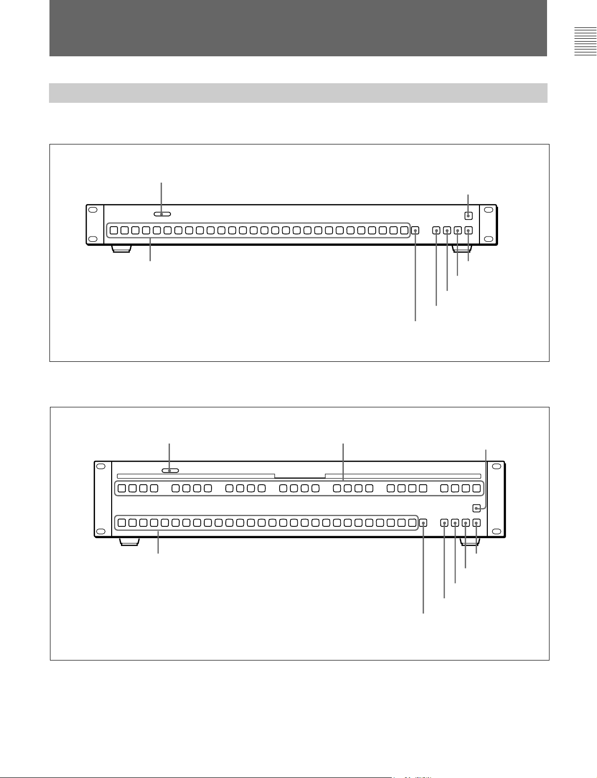
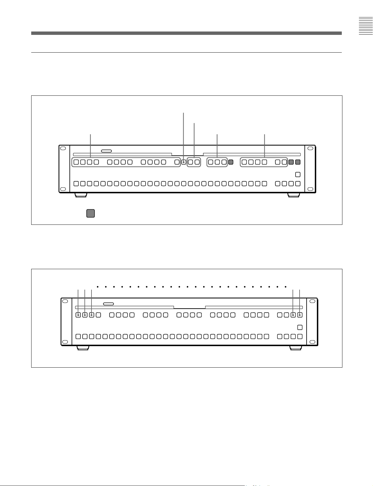
Sony BKDS-7080 User manual

AUX BUS REMOTE CONTROL PANEL
BKDS-7080/7081
OPERATION MANUAL [Japanese/English]
1st Edition
電気製品は、安全のための注意事項を守らないと、
火災や人身事故になることがあります。
•このオペレーションマニュアルには、事故を防ぐための重要な注意事項と
製品の取り扱いかたを示してあります。このオペレーションマニュアルを
よくお読みのうえ、 製品を安全にお使いください。お読みになったあと
は、いつでも見られるところに必ず保管してください。
•本機は電源スイッチを備えていません。
設置の際は、本機の近くの容易に接近できる屋内配線内に専用ブレーカー
またはスイッチを設けるか、または本機の使用中でも容易に抜き差しでき
るコンセントに電源コードを接続してください。
万一、異常が起きた場合は
専用ブレーカーまたはスイッチをOFFにするか、電源コードを抜いてく
ださい。

安全のために
電気製品は、安全のための注意事項を守らないと、火災や感電などにより死亡や
大けがなど人身事故につながることがあり、危険です。
事故を防ぐために次のことを必ずお守りください。
安全のための注意事項を守る
2(J)、3(J)ページの注意事項をよくお読みください。
定期点検を実施する
長期間安全に使用していただくために、定期点検を実施することをおすすめしま
す。点検の内容や費用については、ソニーのサービス担当者または営業担当者に
ご相談ください。
故障したら使用を中止する
ソニーのサービス担当者、または営業担当者にご連絡ください。
万一、異常が起きたら
警告表示の意味
オペレーションマニュアルおよ
び製品では、次のような表示を
しています。表示の内容をよく
理解してから本文をお読みくだ
さい。
この表示の注意事項を守らない
と、火災や感電などにより死亡
や大けがなど人身事故につなが
ることがあります。
この表示の注意事項を守らない
と、感電やその他の事故により
けがをしたり周辺の物品に損害
を与えたりすることがあります。
注意を促す記号
行為を禁止する記号
行為を指示する記号
1電源を切る。
2電源コードや接続コードを抜く。
3ソニーのサービス担当者、または営業担当者に修
理を依頼する。
すぐに電源を切り、消火する。
異常な音、に
おい、煙が出
たら
炎が出たら ,
,
安全のために
日本語

1(J)
警告 ............................................................................................................... 2(J)
注意 ............................................................................................................... 3(J)
概要 .................................................................................................................... 4(J)
対応機種............................................................................................................... 4(J)
特長....................................................................................................................... 4(J)
各部の名称と働き .............................................................................................. 5(J)
前面....................................................................................................................... 5(J)
後面(BKDS-7080とBKDS-7081で共通) .......................................................... 8(J)
接続例 ................................................................................................................ 9(J)
仕様 ..................................................................................................................10(J)
目次
日
本
語

2(J)
下記の注意を守らないと、
火災や感電により
死亡
や
大けが
につながることがあります。
感電火災
警告
外装を外さない、改造しない
外装を外したり、改造したりすると、感電の原因となります。
内部の調整や設定および点検を行う必要がある場合は、必ずサービストレーニン
グを受けた技術者にご依頼ください。
指定の電源コードを使用する
指定以外の電源コードを使用すると、火災や感電の原因となります。
オペレーションマニュアルの中で別売り品として指定されている電源コードをお使
いください。
電源コードを傷つけない
電源コードを傷つけると、火災や感電の原因となります。
•電源コードを加工したり、傷つけたりしない。
•重いものをのせたり、引っ張ったりしない。
•熱器具に近づけたり、加熱したりしない。
•電源コードを抜くときは、必ずプラグを持って抜く。
•ラックマウントするとき、レールにはさみ込まない。
万一、電源コードが傷んだら、ソニーのサービス担当者に交換をご依頼ください。
油煙、湯気、湿気、ほこりの多い場所では設置・使用しない
上記のような場所で設置・使用すると、火災や感電の原因となります。

3(J)
安定した場所に設置する
ぐらついた台の上や傾いたところなどに設置すると、機器が落下してけがの原因
となることがあります。
安全アースを接続する
安全アースを接続しないと、感 電 の 原 因となることがあります。次の方法でアースを
接続してください。
•電源コンセントが 3 極 の 場 合
別売りの電源コードを使用することで安全アースが接続されます。
•電源コンセントが 2 極 の 場 合
別売りの3極→2極の変換プラグを使用
し、変換プラグから出ている緑色のアース
線を建物に備えられているアース端子に
接続してください。
安全アースを取り付けることができない場合は、ソニーのサービス担当者にご相談
ください。
下記の注意を守らないと、
けがをしたり周辺の物品に損害を与えることがあります。
注意
変換プラグ
アース線

4(J)
概要
BKDS-7080/7081は、ソニーのデジタルビデオスイッチャーに接続し、リモートコントロール
によってAUXバスの信号選択を行うための機器です。
対応機種
BKDS-7080/7081は、ソニーの以下のデジタルビデオスイッチャーに対応しています。
接続可能な台数
BKDS-7080/7081は、スイッチャーの 1 つのポートに つ い て 4 台まで のカスケード接続が可
能です。
DVS-7000/7000A、DVS-7200/7200Aでは、7つのポートが使用できるため、BKDS-7080/
7081を合計28台まで接続できます。DVS-7150では、5つのポートで合計20台が接続可能
です。
特長
用途に合わせた2種類のパネル仕様
AUXバスリモートパネルBKDS-7080/7081は、接続されたスイッチャーのAUXバスやエ
ディットプレビューバスなどの信号を切り換えるためのリモートコントロールパネルです。
•BKDS-7080では、設置時に設定した制御対象バスをコントロールします。
•BKDS-7081では、前面のデリゲーションボタンによって制御対象バスを選択します。
最大28台まで接続可能
デジタルビデオスイッチャーのリモートパネル用ポート1つに対して最大4台のBKDS-7080/
7081をカスケード接続することができます。たとえばDVS-7000/7000A/7200/7200Aには7
つのポートがあり、すべてを使用すれば最大28台の接続が可能になります。
スイッチャーコントロールパネルのクロスポイントアサインを適用
操作性を考慮して、スイッチャーコントロールパネルBKDS-7011/7012/7021/7022/7023/
7025/7026のAUXバスブロックと同じ順番でボタンを配列しています。
各ボタンへの信号の割り付けは、スイッチャーコントロールパネルのクロスポイントアサインに
従います。また、スイッチャーのマルチクロスポイントアサイン機能を使用して、コントロール
パネルとは別の割り付けをすることも可能です。
入力拡張システムと標準システムの両方に対応
DVS-7000シリーズの全機種に接続可能です。標準システムだけでなく、ルーティングスイッ
チャーDVS-V6464Mなどを併用する入力拡張システムに組み込むことも可能です。
接続可能なデジタルビデオ
スイッチャー 接続ポート 制御できるバス
DVS-7000/7000A DME1〜DME4
REREMOTE1〜REMOTE3
AUX1〜AUX28、EDITPVW、
FM1、FM2、UTILITYBUS、
MEKEYBUS、DSKBUS(2.5M/
Eまたは1.5M/Eのみ)
DVS-7200/7200A
DVS-7150 DME1、DME4
REMOTE1〜REMOTE3

5(J)
前面
各部の名称と働き
BKDS-7080の前面パネル
1〜8はBKDS-7080とBKDS-7081で共通です。
BKDS-7081の前面パネル
1〜8はBKDS-7080とBKDS-7081で共通です。
2クロスポイント選択ボタン
3SHIFTボタンまたは
クロスポイント選択ボタン
4M/E1ボタン
5M/E2ボタン
6M/E3ボタン
7PGMボタン
8KEYボタン
AUX DELEGATION
2クロスポイント選択ボタン
3SHIFTボタンまたは
クロスポイント選択ボタン
4M/E1ボタン
5M/E2ボタン
6M/E3ボタン
7PGMボタン
8KEYボタン
1オンエアタリー表示用LED
1オンエアタリー表示用LED 9デリゲーションボタン
(BKDS-7081のみ)

6(J)
1オンエアタリー表示用LED
点灯と点滅の別、およびランプの色によって、以下のような状態を
表します。
赤で点灯:本機が制御しているバスの信号が、スイッチャーのプ
ログラム出力の一部を構成している。
本機をスイッチャーのREMOTE2に接続した場合のみ、赤点
灯の条件を変更することができる。
◆詳しくは、スイッチャーのユーザーガイドの「セットアップ 」をご覧
ください。
緑で点灯:プロセッサーとの接続が断線している。
緑で点滅:デリゲーションが未設定。
◆デリゲーションの設定については、インストレーションマニュアルを
参照してください。
2クロスポイント選択ボタン
押すとアンバーで点灯し、その番号に対応するスイッチャーのクロ
スポイントが 選 択されます 。ボタンの上の表示(0〜27)はボタン番号
です。
ボタン番号の割り付けについては、スイッチャーのユーザーガイドを
参照してください。
3シフトボタンまたはクロスポイント選択ボタン
このボタンをシフトボタンとするモードと、クロスポイントボタンとする
モードがあります。
◆モードの設定方法については、インストレーションマニュアルを参照して
ください。
シフトボタンとする場 合:このボタンを押して点灯させると、0〜27
のクロスポイント選択ボタンに30〜57のボタン番号が割り付
けれらます。
クロスポイントボタンとする場合:ボタン番号 28 のボタンになりま
す。
4M/E1ボタン
M/E1ブロックで作成した画像を選択するとき、このボタンを押しま
す。ボタン番号は61です。
5M/E2ボタン
M/E2ブロックで作成した画像を選択するとき、このボタンを押しま
す。ボタン番号は62です。
6M/E3ボタン
3M/Eまたは3.5M/Eシステムでは、M/E3ブロックで作成した画
像を選択するとき、このボタンを押します。
1.5M/Eまたは2.5M/Eシステムでは、PGM/PSTの画像を選択し
ます。
2M/Eシステムではダウンストリームキーヤー(DSK)の出力を選択
します。
ボタン番号は63です。
7PGMボタン
通常はクロスポイント選択ボタンと同じですが、入力拡張システム
では、最終出力を選択するときの専用ボタンになります。ボタン番
号は60です。
8KEYボタン
入力拡張システムでは、このボタンを押しながらクロスポイント選 択
ボタンを 押 すことにより、「KEYレベル」にアサインされた信号を選
択することができます。
標準システムでは、制御対象バスをキーバスにしたときのみ、以下
のように使用します。
•キーソースバスの信号を選択するには、このボタンを押したままク
ロスポイント選択ボタンを押します。
•キーフィルバスの信号を選択するには、このボタンを押さずに、ク
ロスポイント選択ボタンを押します。
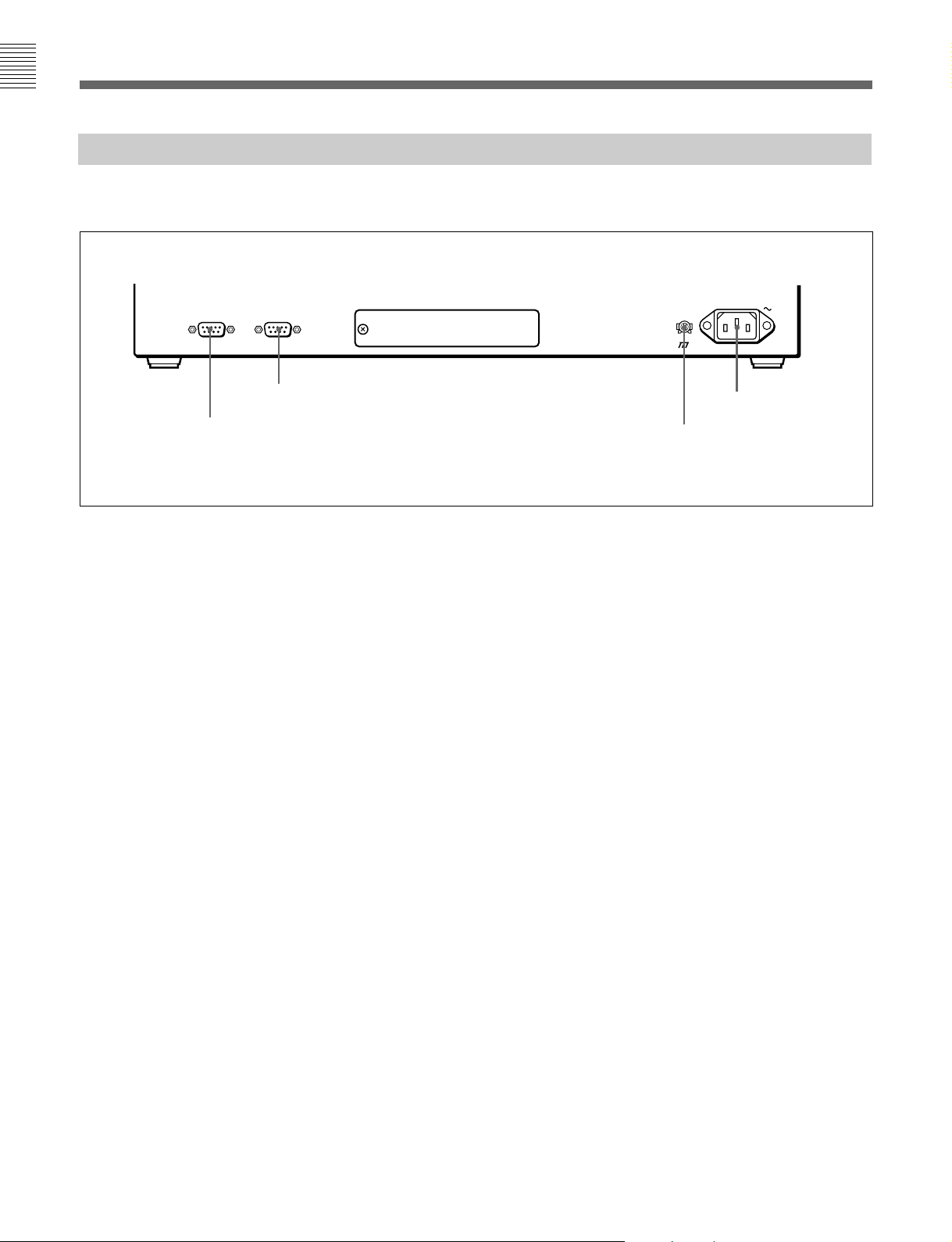
9デリゲーションボタン(BKDS-7081のみ)
制御対象とするバスのボタンを押して点灯させます。
入力拡張システムでは、28個のボタンがどのバスに対応するかに
ついて、2通りの設定ができます。
ボタンとバスの対応については、次ページの図をご覧ください。
各部の名称と働き

7(J)
デリゲーションボタンとバスの対応
標準装備での対応および入力拡張システムでの対応(その1)
(入力拡張システムの場合、M/E2UTILITYとM/E3UTILITYに
該当するボタンは無効になります。)
AUX 1〜13
入力拡張システムでの対応(その2)
入力拡張システムでは、上記のほかに、以下のような設定も可能
です。
◆ 設定方法については、インストレーションマニュアルを参照してください。
AUX DELEGATION
EDIT PVW
FM1、2
M/E1〜3 UTILITY
M/E-1 KEY1、KEY2
M/E-2 KEY1、KEY2
M/E-3 KEY1、KEY2
:未使用
AUX DELEGATION
AUX 1 2 3 27 28

8(J)
後面 (BKDS-7080とBKDS-7081で共通)
1REMOTE2端子
本機をスイッチャーのポートに対して1台目のパネルとして使用す
る場合には、以下の端子のいずれかに接続します。
DVS-7000/7000A/7200/7200Aの端子:DME1〜 DME4、
REMOTE1〜REMOTE3
DVS-7150の端子:DME1、DME2、REMOTE1〜REMOTE3
2台目以降のパネルとして使用する場合には、スイッチャーに近い
方のREMOTE1端子に接続します。
2REMOTE1端子
本機から別のBKDS-7080/7081をカスケード接続する場合、次の
(スイッチャーから遠いほうの)パネルのREMOTE2端子に接続しま
す。
スイッチャーのポートに対して4台までのカスケード接続が可能で
す。
3U(信号用アース)端子
信号用のアース端子です。必要に応じて接地線に接続します。
4-AC IN端子
別売りの電源コードでAC電源に接続します。
AC IN
REMOTE1REMOTE2
2REMOTE1端子
1REMOTE2端子
4-AC IN端子
各部の名称と働き
BKDS-7080とBKDS-7081の後面パネルは、全体の大きさは異な
りますが、端子の名称と働きは同じです。
3U端子

9(J)
接続例
DVS-7000シリーズのデジタルビデオスイッチャーに接続する場合、スイッチャーのポート1つ
について以下のようなカスケード接続が可能です。
デジタルビデオスイッチャーDVS-7000Aの後面
•DVS-7000/7000ADVS-7200/7200Aでは、以下の7つ
の端子に最大28台が接続できる。
DME1〜DME4、REMOTE1〜REMOTE3
•DVS-7150では、以下の5つの端子に最大20台が接続でき
る。 DME1、DME2、REMOTE1〜REMOTE3
ポート1
ポート7
1つのポートに最大4台
AC電源へ
AC電源へ
AC電源へ
AC電源へ

10(J)
仕様
電源電圧 AC100V〜240V±10%、50/60Hz
消費電力 最大0.15A
動作保証温度 5℃〜40℃
性能保証温度 10℃〜35℃
(保存時:−20℃〜+60℃)
湿度範囲 10%〜90%RH
外形寸法 BKDS-7080:482×44×120mm
BKDS-7081:482×88×120mm
(幅/高さ/奥行き、突起部を除く)
質量 BKDS-7080:1.1kg
BKDS-7081:1.9kg
制御用端子 REMOTE1、REMOTE2
RS-422A準拠、D-sub9ピン
付属品 オペレーションマニュアル(1)
インストレーションマニュアル(1)
別売品 AC電源コードDK-2401(J)
仕様および外観は、改良のため予告なく変更することがありますが、ご了承ください。

1(E)
WARNING
To prevent fire or shock hazard, do not expose the unit to
rain or moisture.
To avoid electrical shock, do not open the cabinet. Refer
servicing to qualified personnel only.
VORSICHT
Um Feuergefahr und die Gefahr eines elektrischen
Schlages zu vermeiden, darf das Gerät weder Regen noch
Feuchtigkeit ausgesetzt werden.
Um einen elektrischen Schlag zu vermeiden, darf das
Gehäuse nicht geöffnet werden. Überlassen Sie
Wartungsarbeiten stets nur qualifiziertem Fachpersonal.
For the customers in the USA
This equipment has been tested and found to comply with
the limits for a Class A digital device, pursuant to Part 15 of
the FCC Rules. These limits are designed to provide
reasonable protection against harmful interference when the
equipment is operated in a commercial environment. This
equipment generates, uses, and can radiate radio frequency
energy and, if not installed and used in accordance with the
instruction manual, may cause harmful interference to radio
communications. Operation of this equipment in a
residential area is likely to cause harmful interference in
which case the user will be required to correct the
interference at his own expense.
You are cautioned that any changes or modifications not
expressly approved in this manual could void your authority
to operate this equipment.
The shielded interface cable recommended in this manual
must be used with this equipment in order to comply with
the limits for a digital device pursuant to Subpart B of Part
15 of FCC Rules.
This symbol is intended to alert the user to the
presence of important operating and
maintenance (servicing) instructions in the
literature accompanying the appliance.
WARNING: THIS WARNING IS APPLICABLE FOR USA
ONLY.
If used in USA, use the UL LISTED power cord specified
below.
DO NOT USE ANY OTHER POWER CORD.
Plug Cap Parallel blade with ground pin
(NEMA 5-15P Configuration)
Cord Type SJT, three 16 or 18 AWG wires
Length Less than 2.5 m (8 ft 3 in)
Rating Minimum 10 A, 125 V
Using this unit at a voltage other than 120V may require the
use of a different line cord or attachment plug, or both. To
reduce the risk of fire or electric shock, refer servicing to
qualified service personnel.
English
English
For the customers in Europe
This product with the CE marking complies with both the
EMC Directive (89/336/EEC) and the Low Voltage Directive
(73/23/EEC) issued by the Commission of the European
Community.
Compliance with these directives implies conformity to the
following European standards:
• EN60950: Product Safety
• EN55103-1: Electromagnetic Interference (Emission)
• EN55103-2: Electromagnetic Susceptibility (Immunity)
This product is intended for use in the following
Electromagnetic Environment(s):
E1 (residential), E2 (commercial and light industrial), E3
(urban outdoors) and E4 (controlled EMC environment, ex.
TV studio).
Pour les clients européens
Ce produit portant la marque CE est conforme à la fois à la
Directive sur la compatibilité électromagnétique (EMC) (89/
336/CEE) et à la Directive sur les basses tensions (73/23/
CEE) émises par la Commission de la Communauté
européenne.
La conformité à ces directives implique la conformité aux
normes européennes suivantes:
• EN60950: Sécurité des produits
• EN55103-1: Interférences électromagnétiques (émission)
• EN55103-2: Sensibilité électromagnétique (immunité)
Ce produit est prévu pour être utilisé dans les
environnements électromagnétiques suivants:
E1 (résidentiel), E2 (commercial et industrie légère), E3
(urbain extérieur) et E4 (environnement EMC contrôlé ex.
studio de télévision).
Für Kunden in Europa
Dieses Produkt besitzt die CE-Kennzeichnung und erfüllt
sowohl die EMV-Direktive (89/336/EEC) als auch die
Direktive Niederspannung (73/23/EEC) der EG-
Kommission.
Die Erfüllung dieser Direktiven bedeutet Konformität für die
folgenden Europäischen Normen:
• EN60950: Produktsicherheit
• EN55103-1: Elektromagnetische Interferenz (Emission)
• EN55103-2: Elektromagnetische Empfindlichkeit
(Immunität)
Dieses Produkt ist für den Einsatz unter folgenden
elektromagnetischen Bedingungen ausgelegt:
E1 (Wohnbereich), E2 (kommerzieller und in beschränktem
Maße industrieller Bereich), E3 (Stadtbereich im Freien) und
E4 (kontrollierter EMV-Bereich, z.B. Fernsehstudio)

2(E)
WARNING
This unit has no power switch.
When installing the unit, incorporate a readily accessible
disconnect device in the fixed wiring, or connect the power
cord to a socket-outlet which must be provided near the unit
and easily accessible.
If a fault should occur during operation of the unit, operate the
disconnect device to switch the power supply off, or
disconnect the power cord.
WARNUNG
Dieses Gerät hat keinen Netzschalter.
Beim Einbau des Geräts ist daher im Festkabel ein leicht
zugänglicher Unterbrecher einzufügen, oder das Netzkabel
muß mit einer in der Nähe des Geräts befindlichen, leicht
zugänglichen Wandsteckdose verbunden werden.
Wenn während des Betriebs eine Funktionsstörung auftritt, ist
der Unterbrecher zu betätigen bzw. das Netzkabel
abzuziehen, damit die Stromversorgung zum Gerät
unterbrochen wird.

3(E)
Table of Contents
Overview............................................................................................... 3(E)
Supported Switchers........................................................................3(E)
Features ...........................................................................................4(E)
Names and Functions of Parts............................................................ 5(E)
Front Panel ......................................................................................5(E)
Rear Panel(BKDS-7080 and BKDS-7081) .....................................8(E)
Example Configuration....................................................................... 9(E)
Specifications...................................................................................... 10(E)
Overview
The BKDS-7080/7081 is a remote control panel that can be connected to
Sony digital video switchers to enable selection of AUX bus signals by
remote control.
Supported Switchers
The BKDS-7080/7081 can be used with the following digital video
switchers.
Number of connectable control panels
Up to four BKDS-7080/7081 control panels can be connected to each
switcher port in cascading configurations. The DVS-7000/7000A and
DVS-7200/7200A switchers provide seven connection ports, allowing a
total of 28 control panels to be connected. The DVS-7150 provides five
ports, allowing a total of 20 control panels to be connected.
Connectable video
switcher Connection ports Controllable buses
DVS-7000/7000A DME1 to DME 4
REMOTE 1 to REMOTE 3 AUX 1 to AUX 28, EDIT
PVW,
FM1, FM2, UTILITY BUS
ME KEY BUS, DSK BUS
(2.5M/E or 1.5M/E only)
DVS-7200/7200A
DVS-7150 DME1, DME 4
REMOTE 1 to REMOTE 3

4(E)
Features
Two control panel types, selectable for the application
The BKDS-7080/7081 AUX Bus Remote Control Panel is a remote
control panel that enables switching of signals on switcher buses such as
the AUX or EDIT PVW buses.
•The BKDS-7080 is configured at the time of installation to control
specified buses.
•The BKDS-7081 allows selection of control buses by delegation buttons
on the front panel.
Up to 28 control panels connectable
Up to four BKDS-7080/7081 control panels can be connected in cascading
configurations to each remote panel port on the switcher. The DVS-7000/
7000A and DVS-7200/7200A switchers provide seven ports, allowing 28
control panels to be connected if all ports are used.
Inherits cross-point assignments of switcher control panel
For consistency and ease of operation, buttons on the control panel are
arranged in the same order as buttons in the AUX bus bank of the BKDS-
7011/7012/7021/7023/7025/7026 switcher control panel.
Signal assignments to each button follow the cross-point assignments of
the switcher control panel. The switcher’s cross-point assignment function
may also be used to make assignments that differ from this control panel.
Can be connected to both I/O expansion systems and standard
systems
BKDS-7080/7081 control panels can be connected to any of the DVS-
7000-series switchers including the I/O expansion system using the DVS-
V6464M Digital Video Routing Switcher.
Overview

5(E)
Names and Functions of Parts
BKDS-7080 front panel
1to 8are the same on the BKDS-7080 and BKDS-
7081.
BKDS-7081 front panel
1to 8are the same on the BKDS-7080 and BKDS-
7081.
1On air tally indicator
2Cross-point selection buttons
3SHIFT button or cross-point
selection button
4M/E1 button
5M/E2 button
6M/E3 button
7PGM button
8KEY button
1On air tally indicator
AUX DELEGATION
3SHIFT button or cross-point
selection button
4M/E1 button
5M/E2 button
6M/E3 button
7PGM button
8KEY button
9Delegation buttons
(BKDS-7081 only)
Front Panel
2Cross-point selection buttons

6(E)
Names and Functions of Parts
1On air tally indicator
This indicator lights or flashes in red or green to
indicate the following states.
Lit in red: Signals on the bus controlled by this unit
are part of the switcher’s program output.
The conditions for this indicator lighting in red
can be changed if this control panel is connected
to the switcher’s REMOTE2 connector.
For details, refer to “Setup” in the switcher’s User’s
Guide.
Lit in green: The connection with the processor is
broken.
Flashing in green: No delegation settings.
Refer to the Installation Manual for more information
about delegation settings.
2Cross-point selection buttons
When pressed, these buttons light in amber and select
the switcher cross-point corresponding to the button
number. Button numbers (0 to 28) are indicated on the
faces of the buttons.
For more information about button number assignments,
refer to the switcher’s User’s Guide.
3SHIFT button or cross-point selection
button
This button can be used in SHIFT button mode and
cross-point button mode.
When used as the SHIFT button: When pressed, this
button lights and assigns button numbers 30 to 57 to
the cross-point selection buttons 0 to 27.
When used as a cross-point selection button: This
button becomes cross-point button 28.
Refer to the Installation Manual for more information about
selecting the mode of this button.
4M/E1 button
This button selects the video created with the M/E-1
bank. This button’s number is 61.
5M/E2 button
This button selects the video created with the M/E-2
bank. This button’s number is 62.
6M/E3 button
In a 3M/E or 3.5M/E system, this button selects the
video created with the M/E-3 bank.
In a 1.5M/E or 2.5M/E system, it selects the PGM/PST
video.
In a 2M/E system, it selects the output of the
downstream keyer (DSK).
This button’s number is 63.
7PGM button
Normally this button has the same function as the
cross-point selection buttons, but in an I/O expansion
system it becomes a special button for selection of the
final output. This button’s number is 63.
8KEY button
In an I/O expansion system, this button can be pressed
together with a cross-point selection button to select
the signals assigned to KEY level.
In a standard system, this button can be used as
follows, only when a key bus has been specified as the
control bus.
•To select the key source bus signals, press this button
together with a cross-point selection button.
•To select the key fill bus signals, press a cross-point
selection button without pressing this button.
9Delegation buttons (BKDS-7081 only)
In an I/O expansion system, there are two types of
settings for assignment of the 28 buttons to switcher
buses.
See the figure on the following page for the correspondence
between buttons and buses.

7(E)
Correspondence between delegation buttons and buses
Correspondences in a standard system and in
an I/O expansion system (1)
(In an I/O expansion system, buttons corresponding to
M/E2 UTILITY and M/E3 UTILITY are disabled.)
AUX DELEGATION
AUX 1 to 13
EDIT PVW
FM1
FM2
M/E1-3 UTILITY
M/E-1 KEY1
M/E-1 KEY2
M/E-2 KEY1
M/E-2 KEY2
M/E-3 KEY1
M/E-3 KEY2
Correspondences in an I/O expansion system
(2)
In an I/O expansion system, the following settings are
possible in addition to those indicated above.
Refer to the Installation Manual for more information about
how to make these settings.
AUX DELEGATION
AUX 1 2 3 27 28
: Not used

8(E)
Rear Panel (BKDS-7080 and BKDS-7081)
AC IN
REMOTE1REMOTE2
1REMOTE2 connector
When using this unit as the first control panel
connected to a switcher port, connect to one of the
following switcher connectors.
DVS-7000/7000A/7200/7200A: DME1 to DME4,
REMOTE1 to REMOTE3
DVS-7150: DME1, DME2, REMOTE1 to
REMOTE3
When using this unit as the second or following
control panel in a cascading connection, connect to the
control panel REMOTE1 connector closest to the
switcher.
2REMOTE1 connector
When connecting other BKDS-7080-7081 control
panels to this unit in a cascading connection, connect
to the REMOTE2 connector of the next control panel.
Up to four control panels can be connected in a
cascading connection to each switcher port.
Names and Functions of Parts
The size of the rear panels differ on the BKDS-7080
and BKDS-7081, but the names and functions of the
connectors are the same.
3U (ground) terminal
This is a signal ground. Connect to ground as required.
4-AC IN connector
Connect the optional AC power cord.
3Uterminal
1REMOTE2 connector
2REMOTE1 connector 4-AC IN connector
This manual suits for next models
1
Table of contents
Languages:
Other Sony Control Panel manuals

Sony
Sony MSU-1000 User manual

Sony
Sony RCP-3100 User manual

Sony
Sony BKDS-7025 Instruction Manual

Sony
Sony BKDS-7017 Instruction Manual

Sony
Sony RCP-D50 User manual

Sony
Sony ICP-X7000 User manual

Sony
Sony ICP-X1116 User manual

Sony
Sony UCP-8060E User manual

Sony
Sony RCP-TX7 User manual

Sony
Sony MKS-R4020 User manual

Sony
Sony CCP-9000-C User manual

Sony
Sony RCP-1500 User manual

Sony
Sony MKS-R3210 User manual

Sony
Sony RCP-TX7 User manual

Sony
Sony BKS-R6010 User manual

Sony
Sony CCP-9000A-C User manual

Sony
Sony DME-3000 User manual

Sony
Sony CCP-8000 Series User manual

Sony
Sony BKDM-3020 User manual

Sony
Sony MKS-8010A User manual