Siemens Simatic TI405 User manual
Other Siemens Control Unit manuals
Siemens
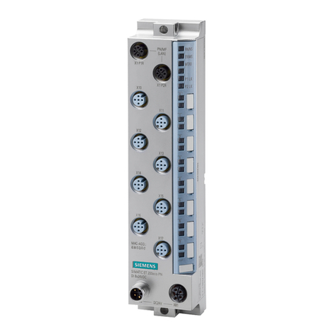
Siemens SIMATIC ET 200eco PN User manual
Siemens
Siemens XDLC User manual
Siemens
Siemens 3VM9.88-0LB10 User manual
Siemens
Siemens SIMOTICS CONNECT 400 User manual
Siemens
Siemens LMV37.4 Series Operator's manual

Siemens
Siemens WFZ56 Series Installation and operation manual
Siemens
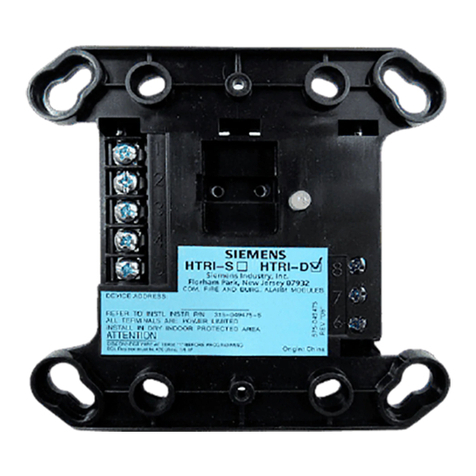
Siemens HTRI-S User manual
Siemens
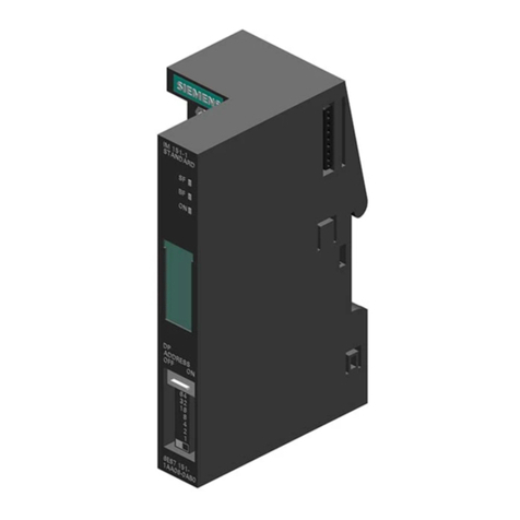
Siemens SIMATIC IM151-1 STANDARD User manual
Siemens
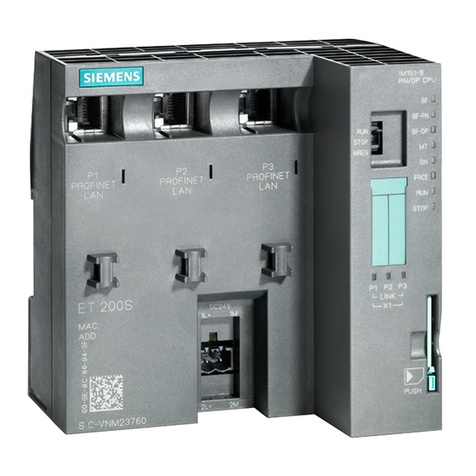
Siemens SIMATIC IM 151/CPU User manual
Siemens
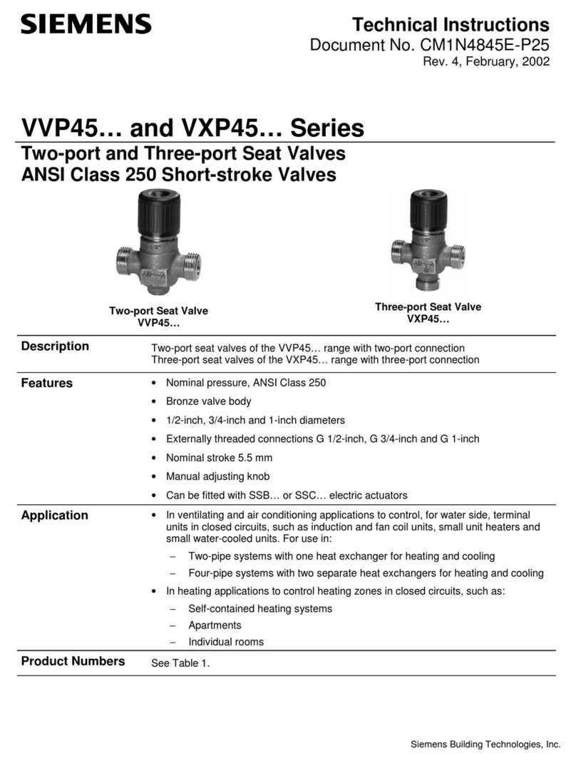
Siemens VXP45 Series Owner's manual
Siemens
Siemens simovert masterdrives User manual

Siemens
Siemens IM 328-N Operating and installation instructions

Siemens
Siemens SINUMERIK 840D sl Parts list manual
Siemens
Siemens SIMATIC 505 PPX:505-6108A User manual
Siemens
Siemens SINUMERIK Series Parts list manual
Siemens
Siemens LOGO! CMK2000 User manual
Siemens
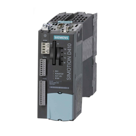
Siemens SIMOTION D410 User manual
Siemens
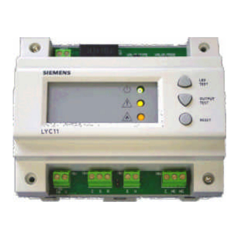
Siemens LYC11 User manual
Siemens
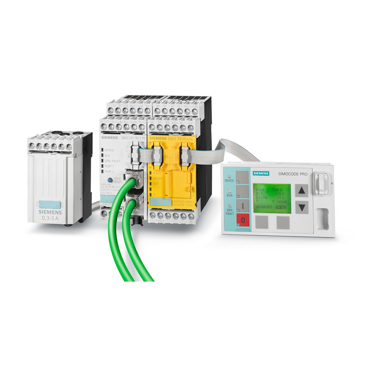
Siemens SIMOCODE pro User manual
Siemens
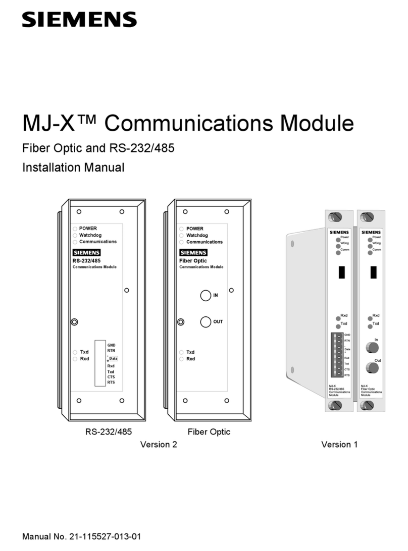
Siemens MJ-X Series User manual
Popular Control Unit manuals by other brands

Festo
Festo Compact Performance CP-FB6-E Brief description

Elo TouchSystems
Elo TouchSystems DMS-SA19P-EXTME Quick installation guide

JS Automation
JS Automation MPC3034A user manual

JAUDT
JAUDT SW GII 6406 Series Translation of the original operating instructions

Spektrum
Spektrum Air Module System manual

BOC Edwards
BOC Edwards Q Series instruction manual

KHADAS
KHADAS BT Magic quick start

Etherma
Etherma eNEXHO-IL Assembly and operating instructions

PMFoundations
PMFoundations Attenuverter Assembly guide

GEA
GEA VARIVENT Operating instruction

Walther Systemtechnik
Walther Systemtechnik VMS-05 Assembly instructions

Altronix
Altronix LINQ8PD Installation and programming manual
