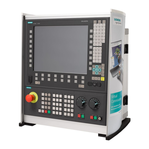
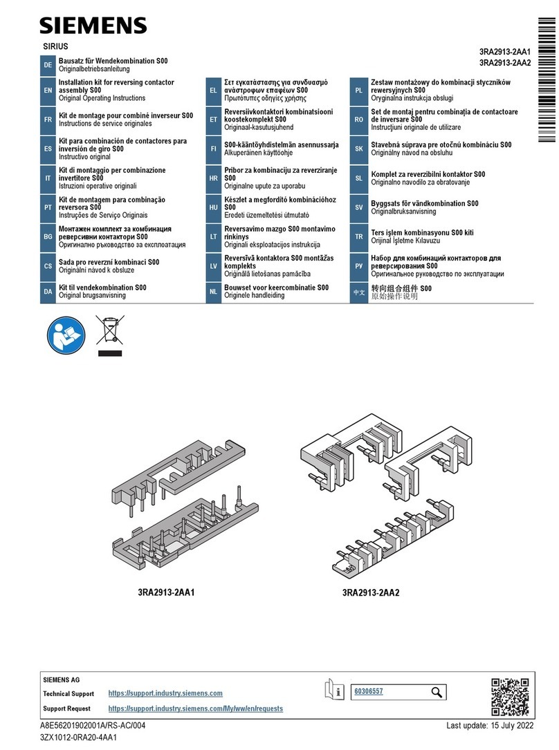
Siemens P1 400A User manual
Other Siemens Industrial Electrical manuals

Siemens
Siemens SENTRON SUPERSWITCH 3KL82 Series User manual
Siemens
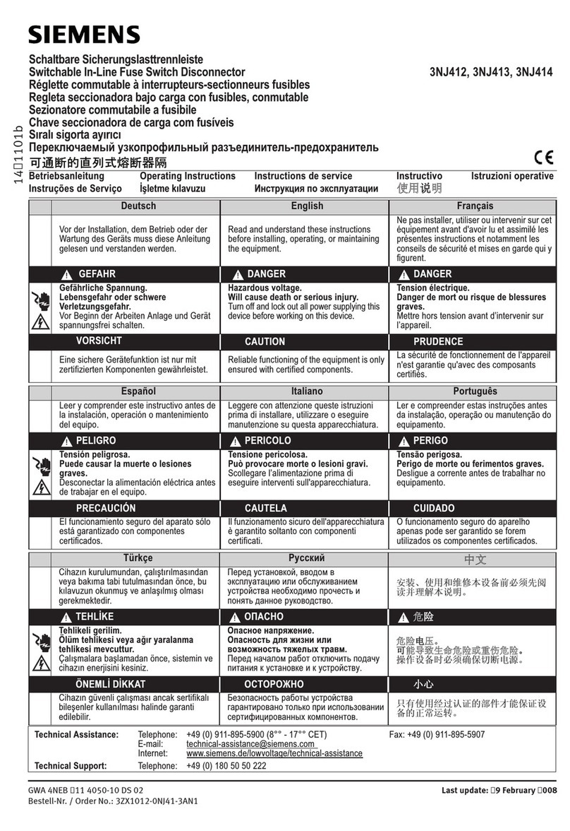
Siemens 3NJ412 User manual
Siemens
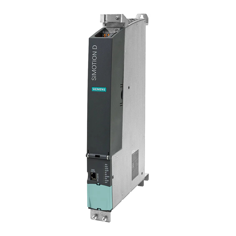
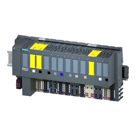
Siemens SIMOTION D45 Series User manual
Siemens
Siemens SIMATIC ET 200SP User manual
Siemens
Siemens 8UC6 Series User manual

Siemens
Siemens SITRANS LVS100 User manual

Siemens
Siemens SIRIUS 3RA232 8 Series User manual
Siemens
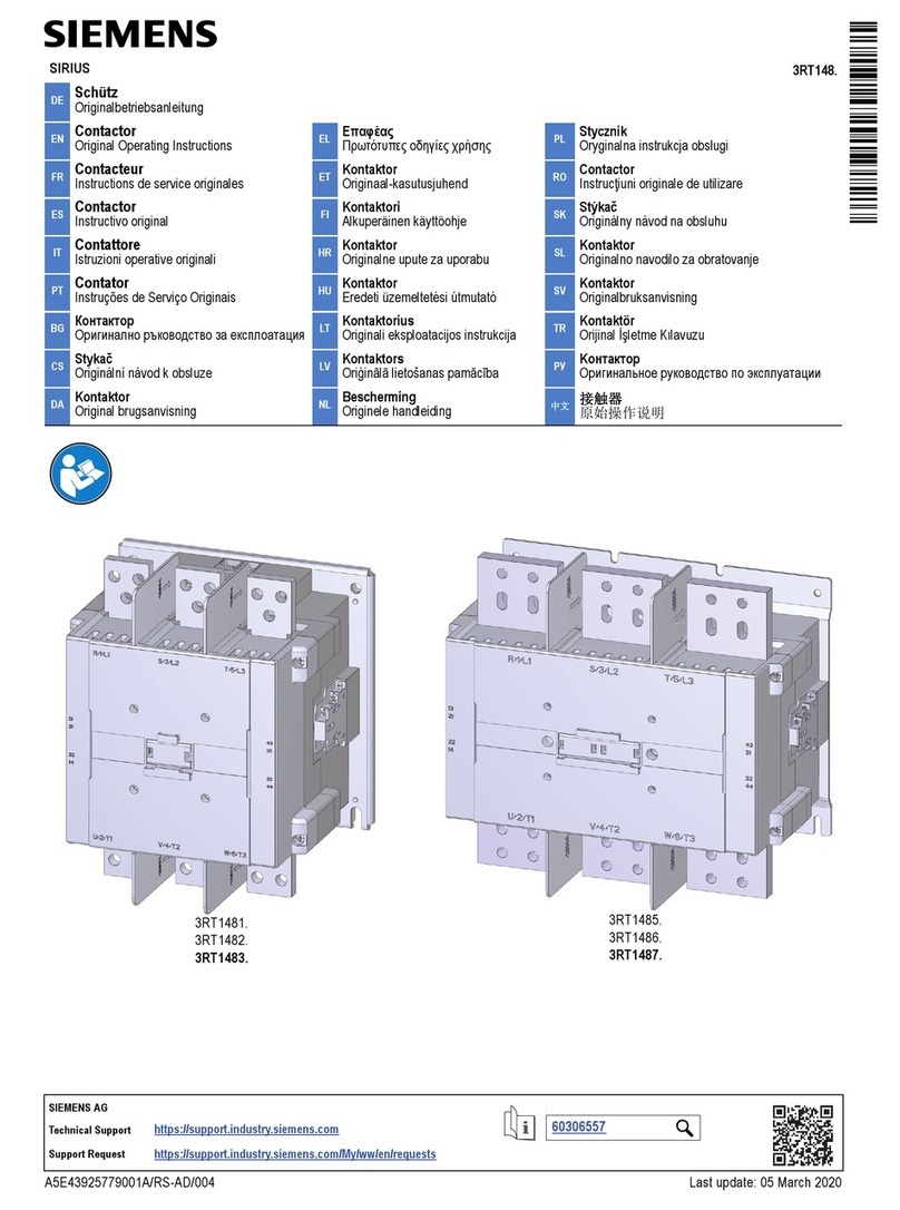
Siemens SIRIUS 3RT148 Series User manual
Siemens
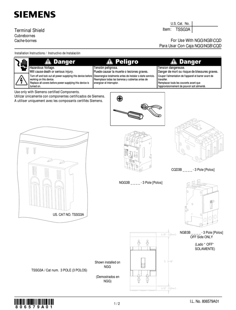
Siemens TSSG3A User manual
Siemens
Siemens SIMATIC RTLS PCB OEM PULSE User manual
Siemens
Siemens SIRIUS 3RA143-8XC21 Series User manual
Siemens
Siemens 8MF1000-2HA User manual
Siemens
Siemens 3WN1 User manual
Siemens
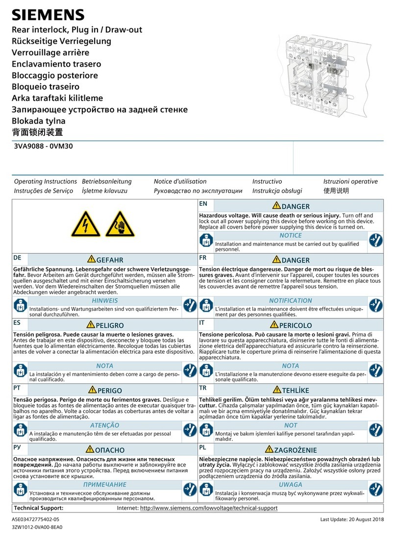
Siemens 3VA9088-0VM30 User manual

Siemens
Siemens 3VA9157-0PK11 User manual

Siemens
Siemens 3VA94-0KP00 Series User manual
Siemens
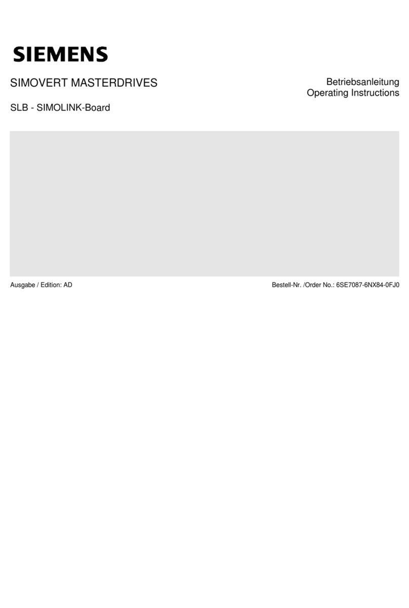
Siemens SIMOVERT MASTERDRIVE SIMOLINK-Board User manual
Siemens
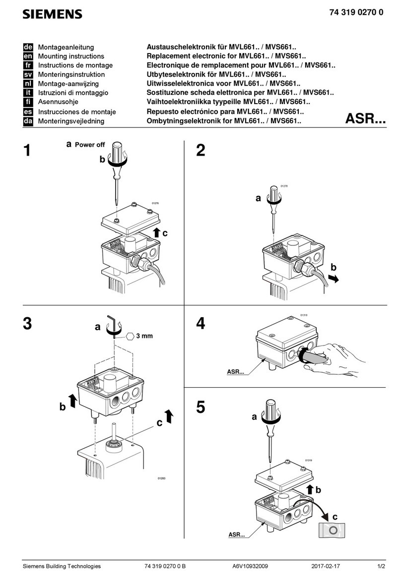
Siemens ASR Series User manual
Siemens
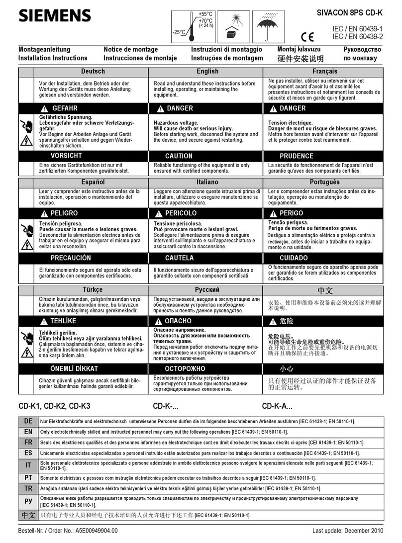
Siemens SIVACON 8PS User manual

Siemens
Siemens Milltronics MILLFLO User manual
Popular Industrial Electrical manuals by other brands

Rexroth Indramat
Rexroth Indramat DURADRIVE SYSTEM200 Project planning manual

Abtech
Abtech HVJB Series Installation, operation & maintenance instructions

Murata
Murata GRM0335C1H8R1DA01 Series Reference sheet

SAF-HOLLAND
SAF-HOLLAND CBX 5415.5 Installation and operation manual

Eaton
Eaton Ulusoy HMH24-04 user manual

Murata
Murata GJM0335C1E4R4BB01 Series Reference sheet

Newlong
Newlong NP-7H NSTRUCTION MANUAL/PARTS LIST

Stahl
Stahl 8575/12 operating instructions

SI
SI Pegasus installation instructions

Murata
Murata GRM1555C1H2R7CA01 Seies Reference sheet

Murata
Murata GRM0225C1E6R4BA03 Series Reference sheet

Cooper Power Systems
Cooper Power Systems VXE15 Installation and operation instructions

S&C
S&C Vista SD manual

Murata
Murata GRM0335C2A7R3CA01 Series Reference sheet

Murata
Murata GRM32ER60G227ME05 Series Reference sheet

Rockwell Automation
Rockwell Automation Allen-Bradley MP-Series installation instructions

Phasemation
Phasemation DG-100 owner's manual
Murata
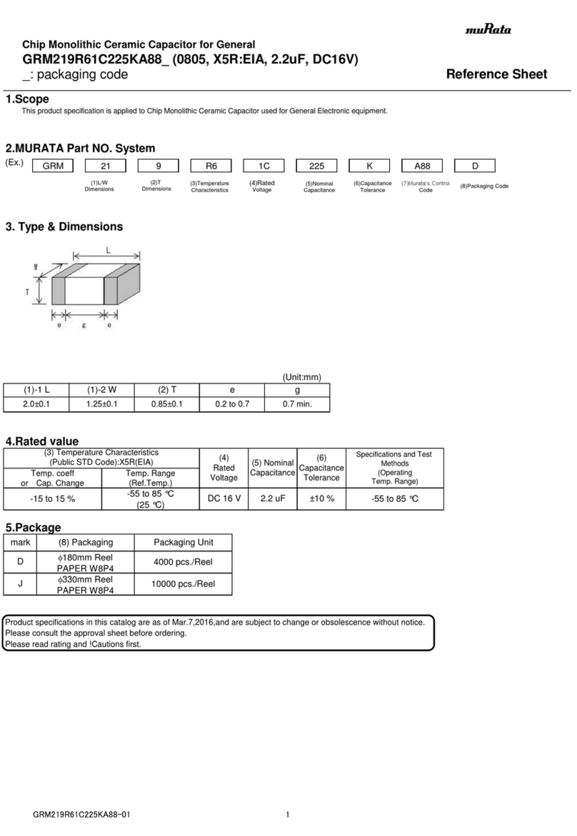
Murata GRM219R61C225KA88 Series Reference sheet
