SIMATIC
Extension Units PROFINET
Quick Install Guide
1.1
Vorbereitungen
Preparations
A5E40503606, 11/2019
1.2 Lieferumfang – Scope of delivery
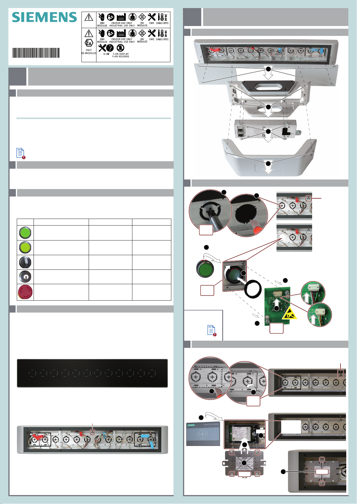
Bedienelemente einbauen
Installing operator controls
2
One Extension Unit, one power supply connector, one connector for the interface X10 and four
screws M4x20 for fixation at the PRO device are contained in the scope of delivery.
Im Lieferumfang sind eine Extension Unit, eine Stromversorgungsklemme, ein Steckverbinder für
die Schnittstelle X10 und vier Schrauben M4x20 zur Befestigung am PRO-Gerät enthalten.
2.1 Bedienelemente einbauen – Mounting operator controls
2.2
2.1 Extension Unit auseinanderbauen – Disassembling the Extension Unit
2
1
3
4
T10
T20
T20
T20
2
Oben / Top
Größe 4
Size 4
3
5
1.2 Nm
6
7
0.5 Nm
Nur das Lesegerät 6GT2831‑6AA50 verwenden! - Use 6GT2831‑6AA50 Reader only!
6GT2831‑6AA50
USB
4
1
1
1.3 Bedienelemente – Operator controls
You will find the following and additional operating elements for the Extension Unit on the internet
(https://mall.industry.siemens.com/mall/en/WW/Catalog/Products/10046164).
Die folgenden und weitere Bedienelemente für die Extension Unit finden Sie im Internet
(https://mall.industry.siemens.com/mall/de/WW/Catalog/Products/10046164).
Leuchtdrucktaster
Illuminated pushbutton
Leuchtmelder
Signal lamp
Wahlschalter
Selector switch
Schlüsselschalter
Key switch
NOT-HALT-Pilzdrucktaster
EMERGENCY STOP
Mushroom Pushbutton
6AV7674-1MB00-0AA0
6AV7674-1MC00-0AA0
6AV7674-1MD00-0AA0
6AV7674-1ME00-0AA0
6AV7674-1MA00-0AA0
Abb. / Fig. Bedienelement / Operator control MLFB
1.4 Einbauplätze auswählen – Selecting the mounting positions
Typ / Type
Standard-Bedienelement
NOT-Halt-Taster
Standard operator control
EMERGENCY Stop button
Standard-Bedienelement
Standard operator control
Standard-Bedienelement
Standard operator control
Standard-Bedienelement
Standard operator control
Vorderseite / Front
112211310495867
2
V14:
≥V15: 133124115106978
Oben / Top
Rückseite / Rear
12 111 210 3948576
13 212 311 410 59687
Beachten Sie, dass sich die Nummerierung der Einbauplätze umkehrt, wenn man die Extension
Unit von der Rückseite betrachtet.
Note that the numbering of the slots is reversed when you view the Extension Unit from the rear.
Es können maximal 2 NOT-Halt-Taster eingebaut werden.
A maximum of 2 emergency stop buttons can be installed.
Die folgenden Abbildungen zeigen die Zuordnung der Einbauplätze von Vorderseite zu Rückseite
am Beispiel der Extension Unit 22“.
The following figures show the assignment of the mounting positions of front and rear side using the
example of the Extension Unit 22“.
Die Einbauplätze sind analog zur Darstellung im TIA Portal in aufsteigender Reihenfolge von links
nach rechts nummeriert.
The slots are numbered the same way as they are shown in TIA Portal, in ascending order from
left to right.
6AV7674‑1MG00‑0AA0
TIA
TIA
V14:
≥V15:
TIA
TIA
Vor Einbau und Inbetriebnahme – Before mounting and commissioning
1.1
WICHTIG: Beachten Sie alle dem Gerät beiliegenden Dokumente und die Betriebsanleitung, bevor
Sie Bedienelemente einbauen und die Extension Unit installieren. Die vollständige Dokumentation des
Geräts finden Sie im Internet (https://support.industry.siemens.com/cs/ww/de/view/109742323).
IMPORTANT: observe all documents enclosed with the device and the operating instructions manual
before mounting operator controls and installing the Extension Unit. You find the complete documen-
tation of the device on the internet (https://support.industry.siemens.com/cs/ww/en/view/109742323).
Das Handbuchsymbol weist auf detaillierte Informationen in der Betriebsanleitung hin.
The manual symbol refers to detailed information in the operating instructions.
Die Extension Unit ist für 16:9 PRO-Geräte für Standfuß (erweiterbar, Flansch unten) und für Tragarm
(erweiterbar, Rundrohr) konzipiert.
The Extension Unit is designed for 16:9 PRO devices for pedestal (extendable, flange bottom) and for
support arm (extendable, round tube).
Weitere Elemente
Additional elements
Lesegerät einbauen – Mounting a reader device
3
Standard operator control
Standard-Bedienlement
EMERGENCY Stop button
NOT-Halt-Taster
4
5
5
6
1.2 Nm
Oben / Top
2
1
Größe 4
Size 4
6-pin
5-pin
0.8 Nm
T10
C
M
Y
CM
MY
CY
CMY
K
hmi_extension_unit_pn_quick_install_guide_page_1.eps 1 12.11.2019 09:59:18hmi_extension_unit_pn_quick_install_guide_page_1.eps 1 12.11.2019 09:59:18


