manuals.online logo
Brands
  1. Home
  2. •
  3. Brands
  4. •
  5. Siemens
  6. •
  7. Servo Drive
  8. •
  9. Siemens SIMODRIVE POSMO SI User manual

Siemens SIMODRIVE POSMO SI User manual

SIMODRIVE POSMO SI/CD/CA
Montageanleitung Tausch PROFIBUS-Einheit Ausgabe 07.06
Assembly Instructions replacing the PROFIBUS unit Edition 07.06
Benutzerhandbuch Deutsch
Bestell–Nr. (MLFB): 6SN2197–0AA20–AP
:Platzhalter für Ausgabestand
User Manual English
Order No. (MLFB): 6SN2197–0AA20–BP
: space for edition
nicht maßstäblich / not to scale
Maße in mm / Dimensions in mm
Siemens AG 2006 All Rights Reserved
GWE–Nr. / GWE No.: A5E00145169 ae Hotline
Tel. / Fax: +49 (0)180 / 5050 – 222 / 223
E-mail: [email protected]
Hinweis / Note
Potentialausgleichsleitung parallel zum
PROFIBUS verlegen.
Potential bonding conductor run in parallel
to PROFIBUS.
4 mm2
1
1
z. B. / e. g.
SIMATIC S7-300 DP
Elektronikstromversorgung
electronics power supply
(z. B. / e. g.: SITOP power, optional)
+24 V
0 V
3 Schrauben
3 screws
M4 x 16
Blindstopfen
Dummy plug
(––> M12)
Eingänge / inputs (X23)
zum nächsten Antrieb
to the next drive
PROFIBUS-Einheit
A
B
M5 x 8
1
2
PROFIBUS + optional Elektronikstromversorgung / PROFIBUS + electronics power supply (optional)
11
24
Ausgänge / outputs (X24)
I1.A 2
1
4
3
5
M
I0.AVS
z. B. / e. g.
BERO 1 z. B. / e. g.
BERO 2
Hinweis / Note
BERO beim Referenzieren ist an PIN 4 anzuschließen!
BERO must be connected to PIN 4 when referencing!
M
2
1
4
3
5
z. B. Relais 2
e. g. relay 2
z. B. Relais 1
e. g. relay 1
O1.A
O0.A
A
B
+24 V
0 V
X20
1)
B1/A1/ /A2/B2/1M/1LP/2LP/2M/
3
2
3
2 3
PROFIBUS-Einheit
Anschlussplan und Verdrahtung PROFIBUS-Einheit / Connection diagram and wiring of PROFIBUS unit
Leitungsvorbereitung bei Anschluss nichtkonfektionierter Leitung / Preparation of cable for connection of non-preassembled cable
Empfohlenes Abmantelwerkzeug / Recommended sheath stripping tool: PROFIBUS FastConnect Stripping Tool (FCS) 6GK1905 6AA00
PROFIBUS unit
PROFIBUS unit
PROFIBUS
Hinweis / Note
Schrauben auch nicht
belegter Anschlüsse fest
anziehen.
Tighten the screws also of
non-assigned connections.
X23
X24
X23 X24
20= 1
21= 2
22= 4
23= 8
24= 16
25= 32
26= 64
ON
1
ON / OFF
ON / OFF
ON / OFF
ON / OFF
Abschlusswiderstand
terminating resistor Teilnehmeradresse
node address
Teilnehmeradresse / node address = 37
1 + 4 + 32 = 37OFF
OFF=0
ON=1
23456 78
ON
1234
Abschlusswiderstand /
terminating resistor = OFF
ON
123456 78
ON
1234
PROFIBUS
Achtung / Notice
M12-Steckverbindung vollständig einschrauben
(Einschraubtiefe 7 mm).
Please ensure the crew-in depth for M12 plug-in
connection 7 mm.
Schaltereinstellung
switch setting
1. Standard herstellen
1. use standard setting
2. Beispiel
2. example
Hinweis / Note
1) Anschluss an PE-Schiene / Connection to PE bar
2) Bei nichtbenutztem Anschluss ist der Blindstopfen mit Werkzeug festzuziehen!
If the connection is not used, the dummy plug must be fixed with the appropriate tools!
Ó
Ó
Ó
oder mit Blindstopfen2)
or with Dummy plug2)
Klemmeinsatz / Dichtung
Clamping insert / Seal
Mutter
Nut
ÓÓ
Ó
Schirm
Shield
12...15
7...12
565
PROFIBUS
1
Anschluss an PROFIBUS-Einheit
Connection to PROFIBIUS unit
O-Ring
O-seal
Schirm muss O-Ring ca. 2 mm überdecken.
The Shield must cover the O-seal by approx. 2 mm.
Überstehende Schirmdrähte glatt abschneiden.
The excess ends of the shielded wires must be cut square.
Verschraubung
Screw fitting
ÓÓ
Ó
Ó
Ó
Ó
Ó
Schirm / Shield
Demontage Stecker von PROFIBUS-Einheit
Disassemble plug connection from the
PROFIBIUS unit
Verschraubung
Screw fitting
ÓÓ
ÓÓ
Blindstopfen
Dummy plug
SIMODRIVE POSMO SI/CD/CA
Montageanleitung Tausch PROFIBUS-Einheit Ausgabe 07.06
Assembly Instructions replacing the PROFIBUS unit Edition 07.06
Benutzerhandbuch Deutsch
Bestell–Nr. (MLFB): 6SN2197–0AA20–AP
:Platzhalter für Ausgabestand
User Manual English
Order No. (MLFB): 6SN2197–0AA20–BP
: space for edition
nicht maßstäblich / not to scale
Maße in mm / Dimensions in mm
Siemens AG 2006 All Rights Reserved
GWE–Nr. / GWE No.: A5E00145169 ae Hotline
Tel. / Fax: +49 (0)180 / 5050 – 222 / 223
E-mail: [email protected]
Wichtige Hinweise
1. Alle Arbeiten dürfen nur von qualifiziertem Fachpersonal durchgeführt werden.
Vor Beginn jeder Arbeit am SIMODRIVE POSMO SI müssen die 5 Sicherheits-
regeln beachtet werden: Freischalten, gegen Wiedereinschalten sichern,
Spannungsfreiheit feststellen, Erden und Kurzschließen und benachbarte
unter Spannung stehende Teile abdecken oder abschranken.
2. Vorsicht beim Anfassen! Beim SIMODRIVE POSMO SI können während des
Betriebs Oberflächentemperaturen von über 100 C auftreten! Brandgefahr!
3. Die Zwischenkreisankopplung ist zum Schutz vor Restspannung mit einer
Sicherheitsverrieglung versehen, die nur mit Werkzeug, z. B. Schrauben-
dreher, von qualifiziertem Personal zu öffnen ist. Das Ziehen der Zwischen-
kreisankopplung darf frühestens 30 min (POSMO SI/CD) / 4 min (POSMO CA)
nach Abschalten der Versorgungsspannung erfolgen!
4. Schutzeinrichtungen auch beim Probebetrieb nicht außer Funktion setzen.
Bei Wellenende mit Passfeder ist beim Probebetrieb ohne Abtriebselemente
die Passfeder zu sichern. Drehrichtung im ungekuppelten Zustand kontrollieren.
5. Für Transport und Montage geeignete Lastaufnahmemittel verwenden.
Die Verriegelungshebel für die Leistungsanschlüsse dürfen nicht zum
Heben und Transportieren verwendet werden.
6. Achtung, elektronisch gefährdete Bauelemente (EGB) vorhanden.
7. Um die Schutzart zu gewährleisten, müssen alle Anschlüsse mit einem
Blindstopfen oder mit einer M-Verschraubung abgedichtet sein.
8. Beim Einsatz von SIMODRIVE POSMO SI/CD/CA in UL-zugelassenen
Anlagen sind die UL-Hinweise im Benutzerhandbuch zu beachten.
9. Alle Leistungsschilder, Warnschilder und Hinweisschilder am
SIMODRIVE POSMO SI/CD/CA sind zu beachten!
10. Das Öffnen der Geräte ist untersagt! Reparatur- und Instandhaltungsarbeiten
sind von einem SIEMENS-Servicezentrum durchzuführen.
11. Nach der Lebensdauer des Produktes sind die einzelnen Teile entsprechend
den landesspezifischen Vorschriften zu entsorgen.
12. Weitere Hinweise sind dem aktuellen Benutzerhandbuch des Produktes
zu entnehmen.
Important Instructions
1. Any work must only be performed by qualified experts. Before you start
working on the SIMODRIVE POSMO SI, you must take care to ensure the
5 safety rules: Isolate, protect against restart, check absence of power,
ground and short-circuit and cover or safeguard adjacent parts which are
under voltage.
2. Be careful when touching the devices! Surface temperatures of more than
100 C may occur on SIMODRIVE POSMO SI during operation!
Danger of fire!
3. In order to protect the dc link from residual voltage, it has been provided
with a safety lock that can only be opened by qualified personnel using
tools such as screwdrivers. The dc link may be decoupled only 30 min.
(POSMO SI/CD) / 4 min. (POSMO CA) after switching off the supply vol-
tage at the earliest!
4. Do not disable the function of the protective devices during test mode.
If the shaft end has a featherkey, secure the featherkey during test mode
without output elements. Check the direction of rotation when it is
disengaged.
5. Please use the appropriate load carrying devices for transport and installa-
tion. The locking levers for the load connections must not be used to lift
and transport the unit.
6. Caution, electrostatically sensitive devices (ESD) present.
7. In order to guarantee the degree of protection, all connections must be
sealed with a dummy plug or a M gland.
8. When using the SIMODRIVE POSMO SI/CD/CA in systems with UL ap-
proval, please read the respective UL notes given in the user manual.
9. Please observe all rating plates, warning labels and notes attached to the
SIMODRIVE POSMO SI/CD/CA!
10. You are not allowed to open the devices! We recommend that your respon-
sible SIEMENS service center performs the repair and maintenance work.
11. When the service life of the product has expired, the individual parts must
be disposed according to the country-specific regulations.
12. Further notes are given in the current user documentation of the product.
!
Gefahr
Danger
!
Warnung
Warning
Vorsicht
Caution
Achtung
Notice
Hinweis
Note
PROFIBUS-Einheit
PROFIBUS unit
3 Schrauben
3 screws
M4 x 16
PROFIBUS-Einheit
PROFIBUS unit
SIMODRIVE POSMO SISIMODRIVE POSMO CD/CA
Folgende Schritte sind zum Tauschen der PROFIBUS-Einheit durchzuführen:
1Antriebstrang spannungsfrei schalten. Vorhandene Stecker an X23...X25 abziehen und Potentialausgleichs-
leitung demontieren.
Switch the drive line into a no-voltage condition. Remove existing plugs from X23...X25 and deinstall equipo-
tential bonding conductor.
2Lösen der drei Befestigungsschrauben von der PROFIBUS-Einheit zur Antriebseinheit und Abziehen der
PROFIBUS-Einheit.
Release the three screws retaining the PROFIBUS unit to the drive and remove the PROFIBUS unit.
3 Schrauben
3 screws
M4 x 16
3Übetragen der am 8poligen DIL-Schalter eingestellten Schalterstellungen (PROFIBUS-Teilnehmeradresse,
Busabschluss beim PROFIBUS) zu der “neuen” PROFIBUS-Einheit.
Transfer the key positions set at the 8-pole DIL switch (PROFIBUS node address, bus termination with PRO-
FIBUS) to the ”new” PROFIBUS unit.
4Lösen der Verdrahtung des PROFIBUS-DP: ––> PROFIBUS-Leitung an Stecker X20 lösen
––> Stecker M20 mit PROFIBUS-Leitung abziehen
Open the wiring of the PROFIBUS-DP: ––> Remove the PROFIBUS cable from plug X20
––> Remove plug M20 with PROFIBUS cable
5PROFIBUS-Einheit mit “neuer” tauschen und Montage in umgekehrter Reihenfolge:
––> PROFIBUS-Leitung mit Stecker M20 montieren und an X20 verdrahten
––> PROFIBUS-Einheit mit drei Befestigungsschrauben an Antriebseinheit montieren
––> Vorhandene Stecker an X23...X25 stecken und wenn erforderlich Potentialausgleichsleitung montieren
Replace the PROFIBUS unit by the ”new one” and install in reverse order:
––> Install the PROFIBUS cable with plug M20 montieren and wire to X20
––> Attach the PROFIBUS unit to the drive unit using three fastening screws
––> Insert existing plugs in X23...X25 and, if required, install equipotential bonding conductor
Ersatzteil PROFIBUS-Einheit
Spare part PROFIBUS unit
Bestell-Nr.:
Order No.
6SN2414–1AA00–0AA0
Hinweis: PROFIBUS-Einheit erst
festschrauben, wenn sie parallel am
Gehäuse aufliegt und angesteckt ist!
Note: Secure the PROFIBUS unit
with screws only when it has been
applied in parallel to the housing and
inserted !
This manual suits for next models

2

Other Siemens Servo Drive manuals

Siemens SINAMICS S120 Quick start guide

Siemens

Siemens SINAMICS S120 Quick start guide

Siemens 1FT6 13 User manual

Siemens

Siemens 1FT6 13 User manual

Siemens sinamics V60 CPM60.1 User manual

Siemens

Siemens sinamics V60 CPM60.1 User manual

Siemens SINAMICS S210 FSA User manual

Siemens

Siemens SINAMICS S210 FSA User manual

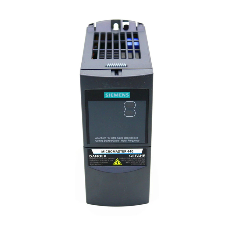
Siemens MICROMASTER 440 User manual

Siemens

Siemens MICROMASTER 440 User manual

Siemens SINAMIC S120 Technical Document

Siemens

Siemens SINAMIC S120 Technical Document

Siemens SINAMICS G130 User manual

Siemens

Siemens SINAMICS G130 User manual

Siemens MICROMASTER 6SE92 User manual

Siemens

Siemens MICROMASTER 6SE92 User manual

Siemens SINAMICS S120 User manual

Siemens

Siemens SINAMICS S120 User manual

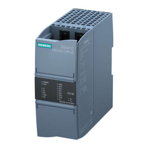
Siemens SIMATIC MICRO-DRIVE Technical Document

Siemens

Siemens SIMATIC MICRO-DRIVE Technical Document

Siemens SIMOTICS S-1FK2 Instruction sheet

Siemens

Siemens SIMOTICS S-1FK2 Instruction sheet

Siemens SIMATIC ET 200SP Technical Document

Siemens

Siemens SIMATIC ET 200SP Technical Document

Siemens SINAMICS S210 User manual

Siemens

Siemens SINAMICS S210 User manual

Siemens SINAMICS S120 User manual

Siemens

Siemens SINAMICS S120 User manual

Siemens SIMOTICS S-1FL6 Administrator guide

Siemens

Siemens SIMOTICS S-1FL6 Administrator guide

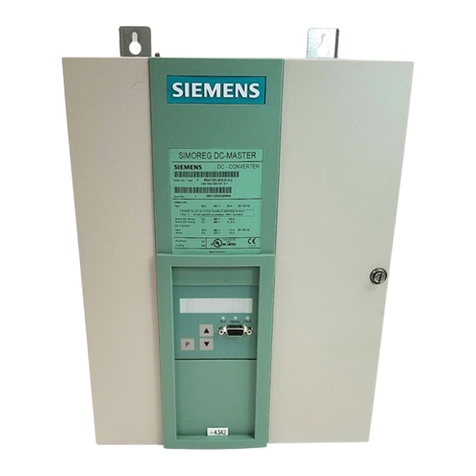
Siemens SIMOREG DC Master 6RA7028-6DS22 User manual

Siemens

Siemens SIMOREG DC Master 6RA7028-6DS22 User manual

Siemens 1FT6031-4AK71-4AH0-Z User manual

Siemens

Siemens 1FT6031-4AK71-4AH0-Z User manual

Siemens SIMATIC SIMOSTEP 1FL3041 Operating and installation instructions

Siemens

Siemens SIMATIC SIMOSTEP 1FL3041 Operating and installation instructions

Siemens SINAMICS S210 User manual

Siemens

Siemens SINAMICS S210 User manual

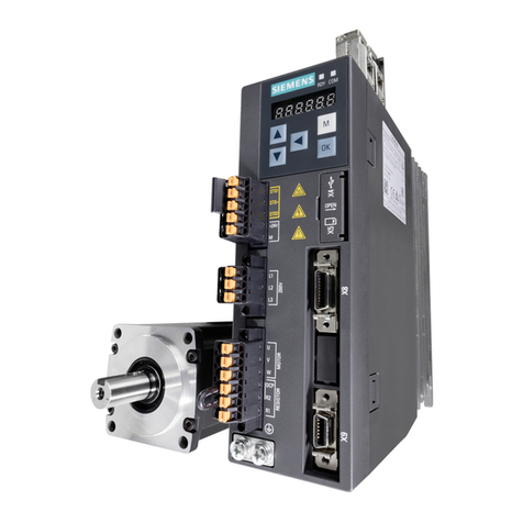
Siemens SINAMICS V90 User manual

Siemens

Siemens SINAMICS V90 User manual

Siemens SINAMICS SIMOTICS S200 PROFINET User manual

Siemens

Siemens SINAMICS SIMOTICS S200 PROFINET User manual

Siemens SINAMICS V90 User manual

Siemens

Siemens SINAMICS V90 User manual

Siemens SINAMICS S210 User manual

Siemens

Siemens SINAMICS S210 User manual

Siemens SINAMICS V90 User manual

Siemens

Siemens SINAMICS V90 User manual

Popular Servo Drive manuals by other brands

Rockwell Automation Allen-Bradley Kinetix 5100 Migration guide

Rockwell Automation

Rockwell Automation Allen-Bradley Kinetix 5100 Migration guide

Rtelligent RS Series quick start guide

Rtelligent

Rtelligent RS Series quick start guide

Fagor 2104 quick reference

Fagor

Fagor 2104 quick reference

YASKAWA CIPR-GA50 AJ Series manual

YASKAWA

YASKAWA CIPR-GA50 AJ Series manual

Xinje DS2-20P7-AS user manual

Xinje

Xinje DS2-20P7-AS user manual

Fireye NEXUS NX20-1 installation instructions

Fireye

Fireye NEXUS NX20-1 installation instructions

ASTRO-PHYSICS GTOCP4 operating instructions

ASTRO-PHYSICS

ASTRO-PHYSICS GTOCP4 operating instructions

Elmo Gold DC Whistle Series installation guide

Elmo

Elmo Gold DC Whistle Series installation guide

Elmo Gold Series Hardware manual

Elmo

Elmo Gold Series Hardware manual

Delta ASDA-A2 Series instruction sheet

Delta

Delta ASDA-A2 Series instruction sheet

SYNAPTICON SOMANET Circulo 7 manual

SYNAPTICON

SYNAPTICON SOMANET Circulo 7 manual

GFA SI 80.12-55,00 Ex installation instructions

GFA

GFA SI 80.12-55,00 Ex installation instructions

Panasonic MINAS A6 Series quick start guide

Panasonic

Panasonic MINAS A6 Series quick start guide

Mitsubishi Electric MELSERVO MR-J4-B Series instruction manual

Mitsubishi Electric

Mitsubishi Electric MELSERVO MR-J4-B Series instruction manual

Hiwin E1 Series manual

Hiwin

Hiwin E1 Series manual

LinMot C1450 VS-1S Series installation guide

LinMot

LinMot C1450 VS-1S Series installation guide

SMC Corporation LECSA series Operation manual

SMC Corporation

SMC Corporation LECSA series Operation manual

Metronix DIS-2 310/2 FB FS STO product manual

Metronix

Metronix DIS-2 310/2 FB FS STO product manual

manuals.online logo
manuals.online logoBrands
  • About & Mission
  • Contact us
  • Privacy Policy
  • Terms and Conditions

Copyright 2025 Manuals.Online. All Rights Reserved.