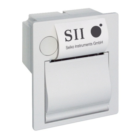
SII MTP Series Use and care manual

MTP SERIES THERMAL PRINTER MECHANISM TECHNICAL REFERENCE
Document Number U00084438003
First Edition January 1995
Second Edition September 2003
Third Edition December 2005
Fourth Edition April 2011
Copyright © 1995, 2003, 2005, 2011 by Seiko Instruments Inc.
All rights reserved.
Seiko Instruments Inc. (hereinafter referred to as “SII”) has prepared this technical reference for use by SII
personnel, licensees, and customers. The information contained herein is the property of SII and shall not be
reproduced in whole or in part without the prior written approval of SII.
SII reserves the right to make changes without notice to the specifications and materials contained herein and
shall not be responsible for any damages (including consequential) caused by reliance on the materials
presented, including but not limited to typographical, arithmetic, or listing errors.
is a trademark of Seiko Instruments Inc.
Downloaded from Arrow.com.Downloaded from Arrow.com.

PREFACE
This reference manual describes the specifications and basic operating procedures for the MTP Series
Thermal Printer Mechanisms. Read it thoroughly so that you are able to use the MTP Series Thermal
Printer Mechanisms properly.
The MTP (RoHS supporting) series has the following eight types of printers.
•MTP102-13B-E
•MTP102-16B-E
•MTP201-20B-E
•MTP201-24B-E
•MTP201-G128-E
•MTP201-G166-E
•MTP401-40B-E
•MTP401-G280-E
In this reference manual, the information mentioned as MTP is common to all models unless otherwise
noted, and if the information is different depending on the model, specific model name is mentioned
clearly.
Fully investigate the intellectual proprietary rights of the sample circuits designed in this manual before
using.
The printer complies with EU RoHS Directive (2002/95/EC).
The printer contains “Pb”, the details are described below.
•a particular free-cutting steel parts, a particular component in glass of the electronic parts
*Lead-containing items listed above are exempt from RoHS (2002/95/EC).
iii
Downloaded from Arrow.com.Downloaded from Arrow.com.Downloaded from Arrow.com.

TABLE OF CONTENTS
Section Page
CHAPTER 1
FEATURES
CHAPTER 2
SPECIFICATIONS
2.1 PART NUMBER................................................................................................................2-1
2.2 GENERAL SPECIFICATIONS..........................................................................................2-2
2.2.1 Character Printers.................................................................................................2-2
2.2.2 Graphic Printers ....................................................................................................2-4
2.3 MOTOR DRIVER CHARACTERISTICS...........................................................................2-6
2.4 TG (TACHO-GENERATOR) OUTPUT CHARACTERISTICS..........................................2-8
2.5 HOME SWITCH................................................................................................................2-9
2.6 THERMAL PRINT HEAD..................................................................................................2-10
2.6.1 Head Specifications...............................................................................................2-10
2.6.2 Head Applied Energy Correction...........................................................................2-11
2.6.3 Head Activation Pulse Width.................................................................................2-12
2.6.4 Control of Printing Pulse Width .............................................................................2-13
2.6.5 Initialization............................................................................................................2-14
2.6.6 Paper Feeding.......................................................................................................2-14
CHAPTER 3
TERMINAL ASSIGNMENT
3.1 B HEAD-MOUNTED PRINTER........................................................................................3-1
3.1.1 Thermal Head Control Terminal............................................................................3-1
3.1.2 Motor and Switch Control Terminal.......................................................................3-2
3.2 G HEAD-MOUNTED PRINTER........................................................................................3-3
3.2.1 Thermal Head Control Terminal............................................................................3-3
3.2.2 Motor and Switch Control Terminal.......................................................................3-3
iv
Downloaded from Arrow.com.Downloaded from Arrow.com.Downloaded from Arrow.com.Downloaded from Arrow.com.
Section Page
CHAPTER 4
TIMING CHART
4.1 TIMING CHART................................................................................................................4-1
4.2 DETAILED CHART OF PRINTING START TIMING........................................................4-3
4.3 CONTINUOUS PRINTING OPERATION.........................................................................4-3
4.3.1 Home Switch Signal Method.................................................................................4-3
4.3.2 Timing Signal Count Method.................................................................................4-4
CHAPTER 5
APPEARANCE AND DIMENSIONS
CHAPTER 6
SAMPLE CIRCUIT BLOCK DIAGRAM
CHAPTER 7
DESIGNING AND HANDLING PRECAUTIONS
7.1 DESIGN PRECAUTIONS.................................................................................................7-1
7.2 HANDLING PRECAUTIONS............................................................................................7-1
CHAPTER 8
DESIGN OF PERIPHERAL DEVICES
8.1 DESIGN PRECAUTIONS.................................................................................................8-1
8.1.1 MTP102 Printer .....................................................................................................8-1
8.1.2 MTP201 and 401 Printers .....................................................................................8-2
8.2 MOUNTING THE PAPER CUTTER.................................................................................8-4
8.3 MOUNTING A ROLL HOLDER FOR HEAD SENSITIVE PAPER ...................................8-5
v
Downloaded from Arrow.com.Downloaded from Arrow.com.Downloaded from Arrow.com.Downloaded from Arrow.com.Downloaded from Arrow.com.
Section Page
8.4 THERMAL PAPER TAKE-UP DEVICE ............................................................................8-6
8.5 FLEXIBLE CABLE ............................................................................................................8-7
8.5.1 Connecting and Fixing the Flexible Cable Terminal .............................................8-7
8.5.2 Bend Radius of Flexible Cable..............................................................................8-7
8.6 REPLACEMENT OF HEAD UNIT ....................................................................................8-8
8.6.1 Removing Head Unit.............................................................................................8-8
8.6.2 Mounting the Head Unit.........................................................................................8-10
TABLES
Table Page
2-1 Character Printer Specifications.......................................................................................2-2
2-2 Graphic Printer Specifications ..........................................................................................2-4
2-3 TG Output.........................................................................................................................2-8
FIGURES
Figure Page
2-1 Motor Drive Characteristics ..............................................................................................2-6
2-2 Motor Drive Signal Timing ................................................................................................2-7
2-3 Sample Motor Drive Circuit...............................................................................................2-7
2-4 Sample TG waveform shaping circuit...............................................................................2-8
2-5 TG Timing Signal..............................................................................................................2-8
2-6 OFF-to-ON Detection........................................................................................................2-9
2-7 ON-to-OFF Detection........................................................................................................2-9
2-8 Sample Thermal Head Drive Circuit.................................................................................2-11
2-9 Pulse Width Control..........................................................................................................2-13
2-10 Sample Pulse Width Control Circuit .................................................................................2-14
vi
Downloaded from Arrow.com.Downloaded from Arrow.com.Downloaded from Arrow.com.Downloaded from Arrow.com.Downloaded from Arrow.com.Downloaded from Arrow.com.
vii
Figure Page
3-1 Thermal Head Control Pin Assignment (B Head-mounted Printer)..................................3-1
3-2 Motor and Switch Control Terminal Assignment (B Head-mounted Printer, MTP102)....3-2
3-3 Motor and Switch Control Terminal Assignment
(B Head-mounted Printer, MTP201 and MTP401)...........................................................3-2
3-4 Thermal Head Control Terminal Assignment (G Head-mounted Printer) ........................3-3
3-5 Motor and Switch Control Terminal Assignment (G Head-mounted Printer) ...................3-3
4-1 Timing Chart .....................................................................................................................4-2
4-2 Printing Start Timing Chart ...............................................................................................4-3
4-3 Continuous Printing Timing Chart (Home Switch Detection Method) ..............................4-3
4-4 Continuous Printing Timing Chart (Timing Signal Method)..............................................4-4
5-1 MTP102 (B head-mounted) Appearance and External Dimensions................................5-2
5-2 MTP201 (B head-mounted) Appearance and External Dimensions................................5-3
5-3 MTP401 (B head-mounted) Appearance and External Dimensions................................5-4
5-4 MTP201 (G head-mounted) Appearance and External Dimensions................................5-5
5-5 MTP401 (G head-mounted) Appearance and External Dimensions................................5-6
6-1 Sample Circuit Block Diagram (B Head-mounted Printer) ...............................................6-2
6-2 Sample Circuit Block Diagram (G Head-mounted Printer)...............................................6-3
8-1 MTP102 Printer (Back).....................................................................................................8-1
8-2 Mounting with Screws (MTP102 printer) ..........................................................................8-1
8-3 Mounting without Screws (MTP102 printer) .....................................................................8-2
8-4 MTP201 and 401 Printers (Back) .....................................................................................8-2
8-5 Mounting with Screws (MTP201 and 401 Printer)............................................................8-3
8-6 Mounting without Screws (MTP201 and 401 Printer).......................................................8-3
8-7 Mounting the Paper Cutter................................................................................................8-4
8-8 Mounting a Roll Holder for Heat Sensitive paper .............................................................8-5
8-9 Roll without Core ..............................................................................................................8-5
8-10 Bend Radius of Flexible Cable .........................................................................................8-7
8-11 Moving the Head Carrier...................................................................................................8-8
8-12 Removing the Flexible Lead Wire.....................................................................................8-8
8-13 Pulling out the Flexible Cable Plate..................................................................................8-9
8-14 Pulling out the Head Unit..................................................................................................8-9
8-15 Inserting the Head Unit Terminal......................................................................................8-10
8-16 Rotating the Head Portion of the Unit...............................................................................8-10
8-17 Sliding the Head along the Guide of the Head Carrier.....................................................8-11
8-18 Pushing the Flexible Cable Plate......................................................................................8-11
8-19 Inserting the Flexible Cable..............................................................................................8-11
Downloaded from Arrow.com.Downloaded from Arrow.com.Downloaded from Arrow.com.Downloaded from Arrow.com.Downloaded from Arrow.com.Downloaded from Arrow.com.Downloaded from Arrow.com.
CHAPTER 1
FEATURES
The MTP Series Line Thermal Printer Mechanism is a series of compact, thermal printers designed to
meet the demand for small, low cost units. It can be used in adding machines, measuring instruments
and analyzers, office machines, medical apparatus, and data terminal devices.
The MTP Series Line Thermal Printer Mechanism has the following features:
•Compact and light weight
•Maintenance-free
•High quality printing
•Battery drive
•Silent, nonimpact system
•Designed for versatile applications
•High reliability
1-1
Downloaded from Arrow.com.Downloaded from Arrow.com.Downloaded from Arrow.com.Downloaded from Arrow.com.Downloaded from Arrow.com.Downloaded from Arrow.com.Downloaded from Arrow.com.Downloaded from Arrow.com.
CHAPTER 2
SPECIFICATIONS
2.1 PART NUMBER
(1) Character printers
MTP -(1): Base model code
(2): Characters per line*
(3): Print head type used
(1) (3)
(2)
* Maximum number of characters per line based on character matrix in General
specifications.
(2) Graphic printers
MTP -(1): Base model code
(3): Print head type used
(4): Maximum number of dots per row per line
(3) (4)
(1)
2-1
Downloaded from Arrow.com.Downloaded from Arrow.com.Downloaded from Arrow.com.Downloaded from Arrow.com.Downloaded from Arrow.com.Downloaded from Arrow.com.Downloaded from Arrow.com.Downloaded from Arrow.com.Downloaded from Arrow.com.
2.2 GENERAL SPECIFICATIONS
2.2.1 Character Printers
Table 2-1 Character Printer Specifications
Item Specifications
Base model code MTP102 MTP201 MTP401
Model MTP102-13B MTP102-16B MTP201-20B MTP201-24B MTP401-40B
Printing method Thermal serial dot printing
Printing direction Left to right with respect to the direction the paper is fed.
Dots per line
(H×W / line) 7 dots ×89 dots 7 dots ×110 dots 7 dots ×138 dots 7 dots ×166 dots 7 dots ×278 dots
Paper feed pitch
(H×W) 0.35mm ×0.30mm 0.35mm ×0.24mm 0.35mm ×0.33mm 0.35mm ×.28mm 0.35mm ×.24mm
Character matrix
(H×W) 7 ×5 dot matrix
Character size
(H×W) 2.4mm ×1.5mm 2.4mm ×1.2mm 2.4mm ×1.6mm 2.4mm ×1.4mm 2.4mm ×1.2mm
Characters per line 13 dot
(2 dot spaces) 16 dot
(2 dot spaces) 20 dot
(2 dot spaces) 24 dot
(2 dot spaces) 40 dot
(2 dot spaces)
Printing width 26.7mm 26.4mm 45.9mm 46.0mm 66.7mm
Printing speed
(room temperature,
5.0V) Approx. 1.5 line / s Approx. 1.2 lines / s Approx. 1.0 line / s Approx. 0.9 line / s Approx. 0.5 line / s
Paper feed pitch 3.8mm
Head activation
timing detection Via a tachogenerator
Home position
detection Via a mechanical switch
Operating voltage
range DC5.0V ±1.0V
2-2
Downloaded from Arrow.com.Downloaded from Arrow.com.Downloaded from Arrow.com.Downloaded from Arrow.com.Downloaded from Arrow.com.Downloaded from Arrow.com.Downloaded from Arrow.com.Downloaded from Arrow.com.Downloaded from Arrow.com.Downloaded from Arrow.com.
Table 2-1 Character Printer specifications (continued)
Item Specifications
Base model code MTP102 MTP201 MTP401
During
printing 3.2A max.
Current
consumption
(room
temperature,
5.0V)
During
paper
feed 250mA max.
Operating temperature
range 0 to 50°C
Storage temperature
range −40 to 60°C
Life span 5 hundred thousand lines (5.0V rated energy, room temperature, “8” full line printing)Note1
Failure rate 10-6 / line or less (5.0V rated energy, room temperature, “8” full line printing)
Operating noise (room
temperature, 5.0V) 70dB or less (back ground noise: 40dB or less, measuring distance: 15 cm, weighing: JIS
A curve, dynamic characteristics: SLOW range)
Paper feed force 0.196N (20gf) or more 0.49N (50gf) or more
Paper hold force 0.49N (50gf) or more 0.98N (100gf) or more
Dimensions
(W ×D ×H) 48 ×31 ×13.8mm 70 ×34 ×14.4mm 91.5 ×35.5 ×20mm
Mass Approx. 35g Approx. 40g Approx. 50g
Paper width 380mm
1- 580mm
1- 80 mm
0
1-
Paper thickness 65 ±5 μm (59 ±5 μm when using TF50KS-E2D)
Recommended
thermal paper
Maker / Sensitivity Normal High sensitivity
Nippon Paper Industries TP50KS-A TF50KS-E2D
Oji Paper Co., Ltd. - PD450
Mitsubishi Paper Co., Ltd. F-200U7N5 F-200U9W3
Note1) Should be no scratches due to foreign material.
2-3
Downloaded from Arrow.com.Downloaded from Arrow.com.Downloaded from Arrow.com.Downloaded from Arrow.com.Downloaded from Arrow.com.Downloaded from Arrow.com.Downloaded from Arrow.com.Downloaded from Arrow.com.Downloaded from Arrow.com.Downloaded from Arrow.com.Downloaded from Arrow.com.
2.2.2 Graphic Printers
Table 2-2 Graphic Printer Specifications
Item Specifications
Base model code MTP201 MTP401
Model MTP201-G128 MTP201-G166 MTP401-G280
Printing method Thermal serial dot printing
Printing direction Left to right with respet to the direction the paper is fed.
Dots per line
(H×W / line) 8 dots ×128 dots 8 dots ×166 dots 8 dots ×280 dots
Paper feed pitch
(H×W) 0.35mm ×0.35mm 0.35mm ×0.28mm 0.35mm ×0.24mm
Character matrix
(H×W) 7 ×5 dot matrix
Character size
(H×W) 2.4mm ×1.7mm 2.4mm ×1.4mm 2.4mm ×1.2mm
Character per line 18 dot
(2 dot spaces) 24 dot
(2 dot spaces) 40 dot
(2 dot spaces)
Printing width 44.7mm 46.0mm 67.2mm
Printing speed (room temperature, 5.0V) Approx. 0.9 line / s Approx. 0.9 line / s Approx. 0.5 line / s
Paper feed pitch 2.8mm
Head activation timing detection Via a tachogenerator
Home position detection Via a mechanical switch
Operating voltage range DC5.0V ±1.0V
2-4
Downloaded from Arrow.com.Downloaded from Arrow.com.Downloaded from Arrow.com.Downloaded from Arrow.com.Downloaded from Arrow.com.Downloaded from Arrow.com.Downloaded from Arrow.com.Downloaded from Arrow.com.Downloaded from Arrow.com.Downloaded from Arrow.com.Downloaded from Arrow.com.Downloaded from Arrow.com.
Table 2-2 Graphic Printer Specifications (continued)
Item Specifications
Base model code MTP201 MTP401
during
printing 3.2A max.
Current
consumption
(room
temperature,
5.0V)
during paper
feed 250mA max
Operating temperature range 0 to 50ºC
Storage temperature range −40 to 60ºC
Life span 5 hundred thousand lines (5.0V rated energy, room temperature, “8” full line printing)Note1
Failure rate 10-6 / line or less (5.0V rated energy, room temperature, “8” full line printing)
Operating noise (room
temperature, 5.0V) 70dB or less (back ground noise: 40dB or less, measuring distance: 15cm, weighing
network: JIS A curve, dynamic characteristics: SLOW range)
Paper feed force 0.196N (20gf) or more
Paper hold force 0.49N (50gf) or more 0.98N (100gf) or more
Dimensions
(W ×D ×H) 70 ×34 ×14.4mm 91.5 ×35.5 ×20mm
Mass Approx. 40g Approx. 50g
Paper width 58 mm
0
1- 0
1-
80 mm
Paper thickness 65 ±5 μm (59 ±5 μm when using TF50KS-E2D)
Recommended thermal paper
Note1) Should be no scratches due to foreign material.
Maker / sensitivity Normal High sensitivity
Nippon Paper Industries TP50KS-A TF50KS-E2D
Oji Paper Co., Ltd. - PD450
Mitsubishi Paper Co., Ltd. F-200U7N5 F-200U9W3
2-5
Downloaded from Arrow.com.Downloaded from Arrow.com.Downloaded from Arrow.com.Downloaded from Arrow.com.Downloaded from Arrow.com.Downloaded from Arrow.com.Downloaded from Arrow.com.Downloaded from Arrow.com.Downloaded from Arrow.com.Downloaded from Arrow.com.Downloaded from Arrow.com.Downloaded from Arrow.com.Downloaded from Arrow.com.

2.3 MOTOR DRIVER CHARACTERISTICS
The motor is the power source for head movement and paper feed. Through the application of DC
voltage to the motor, the head automatically moves back and forth, and paper fed on its return;
therefore, there is no need to reverse the motor.
(1) Motor terminal voltage 5.0 ±1.0 V DC
(2) Motor power consumption
During printing 170 mA max. (room temperature, room humidity, 5.0 V DC)
During paper feeding 250 mA max. (room temperature, room humidity, 5.0 V DC)
Commencing movement 700 mA max. (room temperature, room humidity, 5.0 V DC)
Ceasing movement 500 mA max. (room temperature, room humidity, 5.0 V DC)
Starting
25 ms max.
(when applying the brake)
700 mA max.
Current Paper feeding
Printing
250 mA max.
170 mA max.
Time
500 mA max.
Stopping
Figure 2-1 Motor Drive Characteristics
2-6
Downloaded from Arrow.com.Downloaded from Arrow.com.Downloaded from Arrow.com.Downloaded from Arrow.com.Downloaded from Arrow.com.Downloaded from Arrow.com.Downloaded from Arrow.com.Downloaded from Arrow.com.Downloaded from Arrow.com.Downloaded from Arrow.com.Downloaded from Arrow.com.Downloaded from Arrow.com.Downloaded from Arrow.com.Downloaded from Arrow.com.
(3) Motor stop signal Stop the motor drive signal within 1 ms after detecting a home
switch “OFF” (100 to 250 μs) signal, and input a motor stop
signal of at least 25 ms.
Home switch signal
Motor drive signal
Motor stop signal
1 ms max.
25 ms min.
100-250μs
ON
OFF
* See Section 2.5, Home Switch, for home switch signal.
Figure 2-2 Motor Drive Signal Timing
* When using this circuit, a motor stop signal is not required.
Vcc
IN
M
270Ω
M-
M+
+
-
DTC123E 22kΩ
2SD999
2SD1699
Figure 2-3 Sample Motor Drive Circuit
2-7
Downloaded from Arrow.com.Downloaded from Arrow.com.Downloaded from Arrow.com.Downloaded from Arrow.com.Downloaded from Arrow.com.Downloaded from Arrow.com.Downloaded from Arrow.com.Downloaded from Arrow.com.Downloaded from Arrow.com.Downloaded from Arrow.com.Downloaded from Arrow.com.Downloaded from Arrow.com.Downloaded from Arrow.com.Downloaded from Arrow.com.Downloaded from Arrow.com.
2.4 TG (TACHO-GENERATOR) OUTPUT CHARACTERISTICS
The TG is a signal generator directly connected to the motor, that generates false sine waves of two
cycles per 1 turn of the motor. These waves are converted by a waveform shaping circuit into
rectangular wave signals, which are used as a pulse impression timing signal for the thermal head.
(1) TG output
Table 2-3 TG Output
4 to 6V 5V
Output voltate (Vp-p) 2.0 to 7.0 3.5 to 6.0
Period (ms) 2.5 to 6.5 3.0 to 5.0
(2) Sample TG waveform shaping circuit
180k
Ω
180k
Ω
Vcc
Timing signal
560P
2SC1740
1SS133
TG
Figure 2-4 Sample TG waveform shaping circuit
TG signal
Timing signal
* Generation of the timing signals depends on the user.
Figure 2-5 TG Timing Signal
2-8
Downloaded from Arrow.com.Downloaded from Arrow.com.Downloaded from Arrow.com.Downloaded from Arrow.com.Downloaded from Arrow.com.Downloaded from Arrow.com.Downloaded from Arrow.com.Downloaded from Arrow.com.Downloaded from Arrow.com.Downloaded from Arrow.com.Downloaded from Arrow.com.Downloaded from Arrow.com.Downloaded from Arrow.com.Downloaded from Arrow.com.Downloaded from Arrow.com.Downloaded from Arrow.com.
2.5 HOME SWITCH
The home switch is a push-open type mechanical switch, which switches “OFF” when the head is at the
home position (left end). The switch has two functions. The first is to detect the home position when
the head stops there. Upon returning to the home position, the home switch switches from “ON” to
“OFF”, and brakes are applied to stop the motion of the print head.
The second function is it is used as reference point for starting the counting of the print timing signals.
As the head begins to move to the right from the home position, the home switch switches from “OFF”
to “ON”, at which point counting of the print timing signal begins (TG signals after waveform shaping).
(1) Contact resistance
5 Ωmax. (measuring current: 50 μA)
(2) Current
1.0 mA max. (5.0 V DC)
(3) OFF-to-ON detection
Figure 2-6 OFF-to-ON Detection
This switch has the characteristics that the ON state exists for more than 100 μs within 2 ms of when the
home switch switches from OFF-to-ON. Do not detect the switch until after 1-line has printed after
detection of the first ON detection.
(4) ON-to-OFF detection
Figure 2-7 ON-to-OFF Detection
This switch has the characteristics that the OFF state exists for more than 450 μs within 2 ms of when
the home switch switches from ON-to-OFF. Do not detect the switch for 10 ms after detection of OFF.
2-9
Downloaded from Arrow.com.Downloaded from Arrow.com.Downloaded from Arrow.com.Downloaded from Arrow.com.Downloaded from Arrow.com.Downloaded from Arrow.com.Downloaded from Arrow.com.Downloaded from Arrow.com.Downloaded from Arrow.com.Downloaded from Arrow.com.Downloaded from Arrow.com.Downloaded from Arrow.com.Downloaded from Arrow.com.Downloaded from Arrow.com.Downloaded from Arrow.com.Downloaded from Arrow.com.Downloaded from Arrow.com.
2.6 THERMAL PRINT HEAD
Because the thermal print head in the MTP Series is a thin film type with high thermal efficiency, it has
an excellent print quality. The CPU determines which vertically placed heating units to energize, and
drives them with the thermal head driver (transistor).
2.6.1 Head Specifications
Type of Head B head G Head
Heating unit size Dot 1
Dot 2
Dot 3
Dot 4
Dot 5
Dot 6
Dot 7
Dot 1
Dot 2
Dot 3
Dot 4
Dot 5
Dot 6
Dot 7
Dot 8
2.75
0.3
0.05
2.4
0.3
0.05
0.26
0.26
A rank 15.3 ±1Ω17.6 ±1Ω
B rank 14.0 ±1Ω16.0 ±1Ω
Resistance
value*
C rank 12.7 ±1Ω14.4 ±1Ω
Head applied voltage DC 5.0 ±1V (at FPC terminal)
Peak current
(in simultaneous drive of
all dots at 5.0 V DC) 3.0A max. 3.0A max.
Rated High sensitive thermal paper
2.30mJ
Standard thermal paper
2.50mJ
Head applied
energy
(24°C, 5.0V)
Max. 3.00mJ 3.00mJ
* The resistance value of each dot in the same head may have a 5% dispersion rate, and the average values
are indicated on the rank table above. Rank symbols are printed on the FPC.
2-10
Downloaded from Arrow.com.Downloaded from Arrow.com.Downloaded from Arrow.com.Downloaded from Arrow.com.Downloaded from Arrow.com.Downloaded from Arrow.com.Downloaded from Arrow.com.Downloaded from Arrow.com.Downloaded from Arrow.com.Downloaded from Arrow.com.Downloaded from Arrow.com.Downloaded from Arrow.com.Downloaded from Arrow.com.Downloaded from Arrow.com.Downloaded from Arrow.com.Downloaded from Arrow.com.Downloaded from Arrow.com.Downloaded from Arrow.com.
Vcc
H-COM
Dot 1
2.2kΩ
2SC5585
Head drive
signal 1
・
・
・
・
・
・
・
・
・
・
・
・
10kΩ
10kΩ
2.2kΩ
10kΩ
2.2kΩ
2SC5585
2SC5585
Dot 2
Head drive
signal 2
Head drive
signal 8 Dot 8
Figure 2-8 Sample Thermal Head Drive Circuit
2.6.2 Head Applied Energy Correction
Use the Applied Energy Correction Formula below to correct for when the power voltage and ambient
temperature fluctuation during operation (see sample pulse width control circuit).
Applied energy correction formula
)
100TT
1(E
V2 VV
E0
0
0−
+
+
=
E: Applied energy (mJ)
V: FPC terminal volatage (V)
T: Temperature (°C)
E0:Rated energy (mJ)
B head G head
High sensitive
thermal paper 2.3mJ 2.3mJ
Standard thermal
paper 2.5mJ 2.5mJ
V0:Rated voltage (5.0V)
T0:Room temperature (24°C)
2-11
Downloaded from Arrow.com.Downloaded from Arrow.com.Downloaded from Arrow.com.Downloaded from Arrow.com.Downloaded from Arrow.com.Downloaded from Arrow.com.Downloaded from Arrow.com.Downloaded from Arrow.com.Downloaded from Arrow.com.Downloaded from Arrow.com.Downloaded from Arrow.com.Downloaded from Arrow.com.Downloaded from Arrow.com.Downloaded from Arrow.com.Downloaded from Arrow.com.Downloaded from Arrow.com.Downloaded from Arrow.com.Downloaded from Arrow.com.Downloaded from Arrow.com.
2.6.3 Head Activation Pulse Width
To ensure high quality printing with the MTP Series, the thermal head activation pulse width must be set
according to the head drive voltage and the head resistance.
Pulse width calculation formula
VER
t2
•
=
t: Pulse width for applying rated energy (ms)
R: Head resistance (Ω)
B head G head
A rank 15.3Ω17.6Ω
B rank 14.0Ω16.0Ω
C rank 12.7Ω14.4Ω
E: Applied energy (mJ)
V: FPC terminal volatge (V)
Note: Procedure for pulse width adjustment
(1) Minimize pulse width.
(2) Activate the thermal head with a checked pattern.
(3) Measure the head terminal voltage by using a synchroscope.
(4) Gradually adjust applied pulse width, which is calculated by using
the pulse width calculation formula.
2-12
Downloaded from Arrow.com.Downloaded from Arrow.com.Downloaded from Arrow.com.Downloaded from Arrow.com.Downloaded from Arrow.com.Downloaded from Arrow.com.Downloaded from Arrow.com.Downloaded from Arrow.com.Downloaded from Arrow.com.Downloaded from Arrow.com.Downloaded from Arrow.com.Downloaded from Arrow.com.Downloaded from Arrow.com.Downloaded from Arrow.com.Downloaded from Arrow.com.Downloaded from Arrow.com.Downloaded from Arrow.com.Downloaded from Arrow.com.Downloaded from Arrow.com.Downloaded from Arrow.com.
This manual suits for next models
8
Table of contents
Other SII Printer manuals

SII
SII DPU-S445-00A-E User manual

SII
SII DPU-S445 SERIES Use and care manual

SII
SII IP-7900 User manual

SII
SII MP-A40 SERIES User manual

SII
SII IP-7900-20 User manual

SII
SII DPU-S445 SERIES User manual

SII
SII RP-E10 Series User manual

SII
SII IP-6600-01 User manual

SII
SII LTP3445 Use and care manual

SII
SII SLP720RT Series User manual

SII
SII IP-5610 User manual

SII
SII IP-7900 User manual

SII
SII IP-7900-00 User manual

SII
SII IP-7700-02 User manual

SII
SII Color Painter W-64s User manual

SII
SII IP-6600 User manual

SII
SII IP-6620 User manual

SII
SII DPU-S445 SERIES User manual

SII
SII DPU-3445-30A-E User manual

SII
SII DPU-S245 Use and care manual