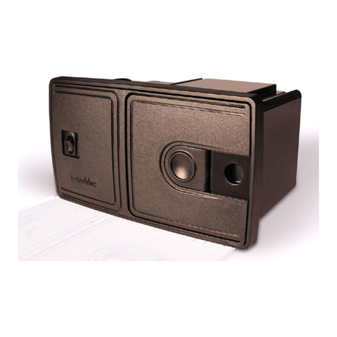
SISTEM AIR MINI TE Installation and operating instructions

INDEX
1 General Information
1.1 - The user guide....................................................................................2
1.2 - Safety and security precautions.......................................................... 2
1.3 - Identification plate...............................................................................3
1.4 - Technical Service Provider................................................................. 3
2 Unpacking
2.1 - Handling and unpacking......................................................................4
2.2 - Control of the accessories...................................................................6
3 Description of the Central Suction Unit
3.1 - Operating Principles............................................................................7
3.2 - Allowed and improper use .................................................................. 8
3.3 - Compliance with EEC Regulations in force ...................................... 8
3.4 - Construction features..........................................................................9
3.5 - Technical features..............................................................................10
3.6 - Description of the computer board ....................................................12
4 Installation
4.1 - Place of installation ...........................................................................13
4.2 - Switch from DX (Right) to SX (Left) model ........................................14
4.3 - Installation of the central suction unit ............................................... 16
4.4 - How to connect the pipe network ......................................................17
4.5 - Electric system ..................................................................................18
5 How to use the central suction unit
5.1 - Starting of the suction unit.................................................................19
5.2 - Use of the suction unit.......................................................................19
6 Maintenance
6.1 - Programmed maintenance.................................................................20
6.2 - Unloading of the dust container........................................................ 21
6.3 - Replacement of the filter cartridge ................................................... 22
6.4 - Reconditioning of the filter cartridge................................................. 23
7 Servicing
7.1 - Servicing criteria...............................................................................23
8 Computer programming for the maintenance (only TECNO ACTIVA line)
8.1 - General information.......................................................................... 24
8.2 - Personalization of the maintenance parameters ............................ 25
8.3 - Visualization of personalized maintenance parameters ................. 27
8.4 - Modify the parameters of a personalized maintenance .................. 28
9 Recommended Spare Parts
9.1 - Spare parts list.................................................................................. 29
10 Dismantling
10.1 - General provisions........................................................................... 29
11 Technical Problems
11.1 - Troubleshooting................................................................................ 30
TA-TE 02/04-01 1
Installation, use and maintenance guide
1 - GENERAL INFORMATION
1.1 The User Guide
The user guide is a fundamental document written by the builder, to be considered
an integral part of the central suction unit. In case of resale, offering or lease to
third parties, the user guide must be handed over to the new user or to the new
owner. The builder must be informed about any ownership change.
We recommend storing and keeping the user guide throughout the whole operating
life of the suction unit.
The main purpose of the user guide is to provide a correct knowledge of the user
mode in order to exploit the best performance and to maintain the central suction
unit at its best working and security conditions.
It is absolutely forbidden to duplicate, copy or release totally or part of this user
guide without previous written authorization by TECNOPLUS Srl, owner of the
trademark SISTEM-AIR.
1.2 Safety and security precautions
Read carefully any information written in this user guide regarding installation, use
and maintenance of the central suction unit.
Never use inappropriately the central suction unit.
Never let the children get near the central suction unit when it is working and never
let the children play with the suction inlets or with the suction unit.
Unplug the central suction unit when:
The power supply cable is worn out or damaged
The central suction unit has been exposed to the inclemency of the weather or to excessive moisture.
The central suction unit has been damaged by an impact or the external container has been damaged
The central suction unit requires any repairing or overhauling.
Always wear protection gloves and mask when carrying out any maintenance
operation, and when unloading the dust container or replacing/cleaning the filter.
Use only SISTEM-AIR original spare parts.
Never use the suction unit to remove textile stuff, big-size bits and pieces of any
material, burning coals or ashes.
Use the suction unit only with the special filter cartridge correctly assembled.
Never block the air exhaust pipes and the cooling inlets of the motor.
Never touch the suction accessories with any part of the body.
Use only one inlet at a time.
If you are not going to use the central suction unit for a short time, it is advisable to
switch it off. If you are not going to use the central suction unit for an extended
period of time, it is advisable to cut it off from the mains power supply.
2TA-TE 02/04-01
Installation, use and maintenance guide
1.4 Technical Service Provider
Call the Builder Technical Service or contact SISTEM AIR authorized centers for
any information you may need. Always specify the technical data indicated on the
identification plate and the serial number of the central suction unit
.
Technical Service Provider
and After-Sales Service
Authorized Technical
Assistance Center
1.3 Identification plate
SISTEM - AIR ITALY
Tel. +39-0381650082 Fax. +39-0381650120
Type: XX-XXXX XX
230 V~ 50 Hz 6.5A 1400W
Mtr. 00-0000-00-G
3
TA-TE 02/04-01
Installation, use and maintenance guide
IPX 4
CE Compliance
Data
Technical Data of the Electric Motor
Serial Number
Name of the Builder
Central Suction Unit Model

2
1
2 - UNPACKING
2.1 Handling and unpacking
Follow the instructions printed on the cardboard box to move the suction unit to the
location selected for the installation.
If necessary, use a trolley to move the suction unit or ask somebody to help you.
Arrange the cardboard box on the floor,
with the opening side upward and cut
the adhesive tape.
4
Installation, use and maintenance guide
SA.FUT. 04-02

3
4
5
6
Open the box, take the straps
with both hands and lift the
suction unit.Arrange it on the
floor in a horizontal position.
Cut the straps.
Remove the upper cardboard
protection, lift the suction unit
and arrange it on the floor in
a vertical position. Remove
the dust-protection bag.
Take out all the accessories contained in the cardboard box
and dispose in compliance with the relevant provisions in force.
Installation, use and maintenance guide
5
SA.FUT. 04-02

2.2 Control of the accessories
Check what you have received:
- One central suction unit
- One metal frame for hanging the suction unit on the wall
- Two couplings made of plastic to connect the suction pipes
- Four metal clamps for fixing the couplings
- An adhesive plate showing the Builder's trademark
- One user guide for correct installation, use and maintenance
- One exhaust silencer made of plastic for the air exhaust
6
Installation, use and maintenance guide
Check that the suction unit and the relevant accessories correspond to what you
have ordered.
Make sure that the suction unit and the accessories have not been damaged
during the handling. If this is the case, do not hesitate to contact the builder.
7
6
5
4
3
2
1
7
1
2
6
5
34
TA-TE 02/04-01

3 - DESCRIPTION OF THE CENTRAL SUCTION UNIT
3.1 Operating principles
The central suction system, suitable for any kind of residential building (house,
office, hotels, service building) consists of a net of PVC pipes spreading out in
every room and perfectly chased in walls and false ceilings. The suction pipe
network is equipped with suction inlets where the user fits the suction hose.
The SISTEM-AIR central suction unit must be installed in a separated room (for
example in a storage room, in a garage or in another service room) and is
connected to the suction pipes network.
The user starts the suction unit by simply inserting the fitting of the suction hose
into the suction pipe inlet.
If the pipe network is not equipped with an electric system, it is possible to install
remotely controlled starting and stop functions, controlled by means of a
remote-control device (supplied upon request).
7
TA-TE 02/04-01
Installation, use and maintenance guide

3.2 Allowed and improper use
The SISTEM-AIR central suction unit model SA..., has been designed to remove
the dust, small-size solid bits and pieces and dry materials.
It is forbidden to use the suction system to remove textile stuff, big-size bits and
pieces, burning and hot materials.
It is strictly forbidden to remove highly explosive materials (gun powder) or inert
materials, which can trigger dangerous chemical reactions if removed separately
and then mixed up in the dust container.
It is strictly forbidden to use the central suction unit in explosion hazard places or in
places where temperature, pressure and moisture are out-of-range.
3.3 Compliance with the requirements and the relevant provisions of
the EEC Directives in force
The suction units model SA..., which are the object of this user guide, fully comply
with the requirements and the relevant provisions of the EEC Directives detailed
hereunder:
98/37/EEC - Machines Directive (ex 89/392/EEC)
74/23/EEC - Low tension Directive (and following modifications)
89/336/EEC -
Electromagnetic Compatibility Directive (and following modifications)
Any different use is strictly forbidden.
The builder, by means of written authorization, must approve
any alteration or modification of the suction unit to remove a
specific material.
Any use different from the original is to be considered
improper and health risk for the user and damage to the
suction unit cannot be excluded.
8
Installation, use and maintenance guide
TA-TE 02/04-01

3.4 Construction features (see picture)
The TECNO Line single-phase suction units for civil sector are divided in two main
categories:
TECNO Evolution Line (models SA... TE)
TECNO Activa Line (models SA... TA)
The two lines of products, equipped with the same motor power, feature the same
construction technology and grant the same performances.
The central suction units of TECNO Activa Line are equipped with computers, which
control the maintenance cycles and indicate when it's time to carry out maintenance
operations.
Soundproofing top cover
Electronic card supporting panel
Power unit
Air exhaust
Start push-button
Dust inlet
Filter cartridge
Body
Conveyor cone
Handle and clamping hook
Computer for maintenance operations (only for TECNO Activa central suction unit)
Dust container
Start input signal
Power supply inlet
Servicing signal output
(only for TECNO Activa central suction unit)
9
TA-TE 02/04-01
Installation, use and maintenance guide
3.5 Technical features (See picture and table)
10
Installation, use and maintenance guide
TA-TE 02/04-01

11
TA-TE 02/04-01
Installation, use and maintenance guide

RESET
PROG
PIN
POWER
ON
1
2
3
4
5
9
13
12
11
10
876
TA-TE 02/04-01
12
Installation, use and maintenance guide
3.6 Description of the computer board (see picture)
(only for TECNO Activa line)
1 - PROG
Led
It switches on when the computer programming function has been activated
2 - PIN
Led
It switches on when the computer programming function has been activated to
display the PIN code
3 - FILTER CARTRIDGE CLEANING WARNING MESSAGE
Led
If on , it indicates that the filter cartridge must be cleaned
4 - DUST CONTAINER UNLOADING WARNING MESSAGE
Led
If on , it indicates that the dust container must be unloaded
5 - MOTOR MAINTENANCE WARNING MESSAGE
Led
If on , call the Maintenance Service to carry out motor servicing
6 - +
key
It is used during programming operations to increase the value indicated on the display
7 - -
key
It is used during programming operations to decrease the value indicated on the display
8 - CURSOR
key
It is used during programming operations to display the different parameters
9 - ENTER
key
It is used during programming operations to store new parameters
10 - POWER
Led
If on , it indicates that the line is powered and the central suction unit is ready to be used
11 - ON
Led
If on , it indicated that the central suction unit has been activated
12 - RESET
key
Once the maintenance operations have been carried out, press this key to set
the alarm system timer to zero
13 - DISPLAY
Window
When the central suction unit is operating small dashes flash on this window, while
during programming operations the values of the stored parameters are displayed

4 - INSTALLATION
- ATTENTION -
THE UNDERMENTIONED OPERATIONS MUST
BE CARRIED OUT BY QUALIFIED STAFF
4.1 Place of installation
Before installing the central suction system, a suction pipes network must installed
by qualified staff. The qualified operators must also spot the best location to install
the suction unit.
Suggestions for a correct installation are detailed hereinafter.
If the central suction system has to be installed in a multistorey building, the suction
unit must be located at the lowest level of the building. The suction unit can be
installed in a service room (for example in a garage or in a storage room), sheltered
from atmospheric agents and protected from moisture and temperature changes.
Chose a space far from heat sources (burners or radiators).
Leave free and well-lit space all around the suction unit to allow trouble-free
maintenance and repair operations.
For any question do not hesitate to contact the Builder's Technical Assistance Service.
13
TA-TE 02/04-01
Installation, use and maintenance guide
14 TA-TE 02/04-01
4
3
2
1
Assemble the panel on the opposite side.
Loosen the screws and remove
the rear fixing plate.
Remove the plate, loosen the screws assembled
below and remove the front panel.
Loosen the screws and
remove the top cover.
4.2 Switch from DX (right) to SX (left) model
The suction units included in the TECNO line are usually delivered suction and
exhaust pipes connections assembled on the right side of the unit (DX model);
when necessary, it is possible to switch the suction unit from DX (right) to SX (left)
model by assembling the inlets of the pipes on the left side (SX model).
Follow the instructions detailed below to switch from DX (right) to SX (left) model:
Installation, use and maintenance guide

15
TA-TE 02/04-01
Installation, use and maintenance guide
Fix the adhesive plate supplied
with the central suction unit.
7
6
5
8
Plug the card cable in the special guides
and assemble the dustproof spongy
disk to seal the opening
(Only for TECNO Activa Line).
Assemble the top cover.
Assemble the fixing plate.

4
3
2
1
Hang the suction unit to the frame.
Position the special frame provided with the
suction unit and lay out the reference points.
(if the drilling has already been carried out, go to step 3)
Measure "X": Mod. TA/TE 050,100, 200, 400= Minimum 500 mm
Measure "X": Mod. TA/TE Mini, Media, Media Plus= Minimum 350 mm
Drill the holes into the wall.
Arrange the frame on the wall.
4.3 Installation of the central suction unit
You must use the special frame (provided with the suction unit) and the special
screws to hang the central suction unit firmly and permanently to a wall.
Remember that the suction unit must hold up the equivalent of eight times the
weight of the suction unit (please refer to par. 3.5 table).
The operator must hang the suction unit at a suitable distance from the floor to allow
an easy unloading of the dust container and a trouble-freer replacement of the filter.
Follow the instructions detailed herebelow to hang correctly the suction unit to the wall:
TA-TE 02/04-01
16
Installation, use and maintenance guide

4.4 How to connect the pipe network (see picture)
- Use the correct fitting to connect the suction unit to the suction hose
- Use the correct fitting to connect the suction unit to the air exhaust pipe
- Stick the silencer on the exhaust pipe near the exhaust grid
3
1
2
17
TA-TE 02/04-01
Installation, use and maintenance guide
3
2
1

1
3
2
4.5 Electrical connection
ATTENTION: The electrical connection must be carried out
by duly qualified staff ONLY
Before plugging in the suction unit, make sure that the mains
power supply corresponds to the central suction unit power supply
(please refer to data indicated on the identification plate).
Connect the activation entry signal cable to low safety tension.
The builder decli
nes all responsibility for damages to persons or objects
due to an electric system not in compliance with the regulations in force.
Follow the instructions to carry out this operation correctly (see picture)
- Connect the starting signal input cable.
- Connect the exit cable for the ausiliary maintenance signal (only for central Tecno
Activa). The use of this signal is an optional. Note: this signal is activated by
a relay which is assembled inside the suction unit and it is a dead contact normally
open (N.O) to be powered with a 12 V. - 0,10 A MAX voltage.
- Insert the electrical plug into the appropriate power outlet.
18 TA-TE 02/04-01
Installation, use and maintenance guide
1
3
2
Ausiliary signal (optional)
Power supply
Micro line

1
2
5.1 Starting of the suction unit
5.2 Use of the suction unit
Press the start push-button.
A red lamp will light up inside.
Fit the accessory suitable
for the cleaning operations
you want to carry out
in the hose.
Fit the opposite end of the hose in the suction inlet.
The suction system will start automatically.
19
TA-TE 02/04-01
Installation, use and maintenance guide
5 -
HOW TO USE THE CENTRAL SUCTION UNIT
After finishing the cleaning operations, remove the hose from the suction inlet and
push gently the cover until it engages. The cover must be engaged gently to avoid
any backstroke of the cover against the suction inlet; allow the suction unit a few
minutes to stop.

6 -
MAINTENANCE
- ATTENTION -
ALWAYS UNPLUG THE POWER SUPPLY CABLE FROM
THEPOWER SUPPLY SOCKET AND ALWAYS WEAR
PROTECTION GLOVES AND GOGGLES BEFORE
CARRYING OUT ANY TECHNICAL OR
MAINTENANCE OPERATION
6.1 Programmed maintenance
In order to keep the system perfectly operating and to avoid any possible mechanic
trouble, the user must overhaul the whole system at precise time intervals,
according to the accumulated operating time of the central suction system.
The central suction units of our TECNO Activa line are equipped with a computer to
control the maintenance routine.
In particular, the system indicates when the dust bag must be unloaded, when it is
necessary to check the functioning of the suction motor and when the dust cartridge
must be cleaned.
Furthermore, a special device (supplied on demand) warns the user by means of a
remote control system when it is necessary to carry out maintenance operations or
connect directly to the service provider, if a maintenance contract has been previously
agreed.
For central suction units of TECNO Evolution Line, which are not equipped with a
computer for maintenance purposes, keep to the instruction detailed in the table below:
The casing of the suction unit needs periodically cleaning. Use a smooth and damp
cloth with some neutral soap.
Attention: Be sure to use only water or water with neutral soap. Alcool or other
solvents may damage the unit. Wait until the unit is perfectly dry prior to start it.
20 TA-TE 02/04-01
Installation, use and maintenance guide
4 Clean the filter cartridge User
6 Unload the dust container User
32 Replace the filter cartridge User
400 Replace the electric motor carbons Technical Service
Carried out by
54
Control the obstruction level of the air exhaust
Technical Service
Time (Hours) Type of intervention
This manual suits for next models
25
Table of contents
Other SISTEM AIR Central Vacuum System manuals

SISTEM AIR
SISTEM AIR Wolly2 Operating instructions

SISTEM AIR
SISTEM AIR FLISY 2 Operating instructions

SISTEM AIR
SISTEM AIR TECNO R-evolution User manual

SISTEM AIR
SISTEM AIR SENSE User manual

SISTEM AIR
SISTEM AIR Revo Block Professional Series User manual

SISTEM AIR
SISTEM AIR TECNO Style User manual

SISTEM AIR
SISTEM AIR JOLLY Installation and operating instructions

SISTEM AIR
SISTEM AIR Industrial Clean Basic User manual

SISTEM AIR
SISTEM AIR speedy User manual