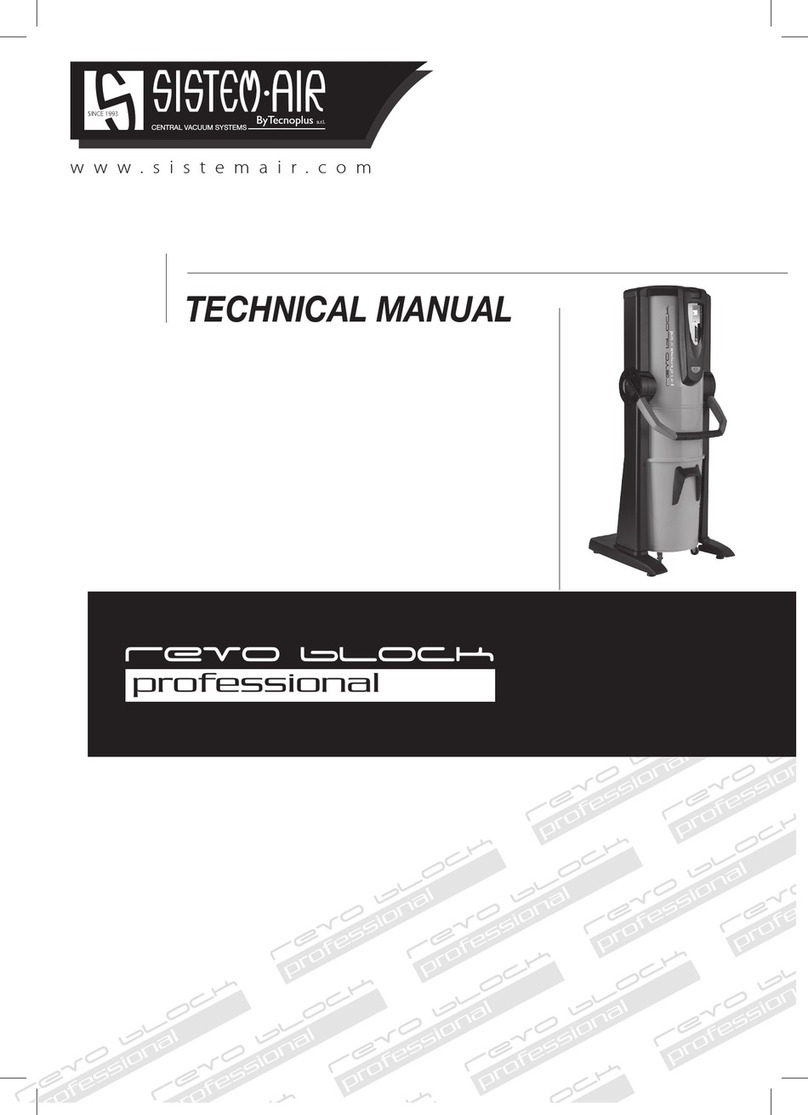
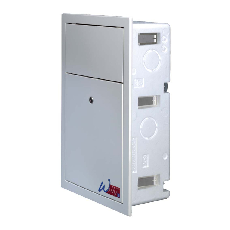
SISTEM AIR TECNO R-evolution User manual

www.sistemair.com
CENTRAL VACUUM SYSTEMS ByTecnoplus s.r.l.
Domestic
Domestic
Domestic
Domestic
Domest
Domestic
omestic
Domestic
Dom
Domestic
Domestic
Technical manual


Domestic
Domestic
Domestic
Domestic
Domestic
Domestic
Domestic
Domestic
Domestic
Domestic
Domestic
Domestic
o
Do
Domestic
stic
1
• Type: domestic vacuum cleaner
• Model: TECNO
• Revision 1.0.0
Line
TECNO
INSTRUCTION MANUAL
12/05/16 Rev:1.0.0
c
omestic
1 TECHNICAL DATA 2
2 AUTHORIZED USE OF THE VACUUM CLEANER 3
2.1 Using the service socket 3
3 UNAUTHORIZED USE OF THE VACUUM CLEANER 3
4 SAFETY FEATURES 4
4.1 Warning 4
4.2 IP protection degree 5
4.3 Electrical insulation degree 5
4.4 Declaration of absence of dangerous substances 5
4.5 Fixed closure guards safety 5
4.5 Movable closure guards safety 6
4.6 Identification plate 6
5 Transforming DX version (outlet pipes fitted on the right) into
SX version (outlet pipes fitted on the left) 6
6 INSTALLATION 8
6.1 Preliminary operations 8
6.2 Place of installation 8
6.3 Fixing the system to the wall 9
6.4 Connection to the pipe network 10
6.5 Electrical connection 11
7 MAINTENANCE 12
7.1 Routine maintenance 12
7.2 Programmed routine maintenance 12
7.3 Extraordinary maintenance 13
7.4 Cleaning the suction container (cylinder) 13
7.5 Emptying the dust bin 13
7.6 Filter cartridge cleaning 14
8 REPAIRS AND SPARE PARTS 15
10.1 Intervention criteria 15
10.2 Recommended spare parts 15
9 TROUBLESHOOTING 16
9.1 Thermal switch 16
10 TECNO LINE EXPLODED VIEWS 18
INDEX

Instruction manual TECNO line
212/05/16 Rev:1.0.0
CENTRAL VACUUMSYSTEMS ByTecnoplus s.r.l.
TECNO R-evolution TECNO Style
Model
Article
Tecno
R-evolution
150
Tecno
R-evolution
250
Tecno
R-evolution
350
Tecno
R-evolution
450
Tecno
Style
MINI
Tecno
Style
150
Tecno
Style
250
Tecno
Style
350
Tecno
Style
450
3110.2T 3112.2T 3113.3T 3115.3T
3107.1TER 3110.1TER 3112.1TER 3113.3TER 3115.3TER
Service inlet YES YES YES YES NO YES YES YES YES
Computer maintenance YES YES YES YES NO NO NO NO NO
Suction coupling Ø mm 50 50 50 50 50 50 50 50 50
IP Protection Degree IP 44 44 44 44 44 44 44 44 44
Powewr supply V ac
220/240 220/240 220/240 220/240 220/240 220/240 220/240 220/240 220/240
Frequency Hz 50/60 50/60 50/60 50/60 50/60 50/60 50/60 50/60 50/60
Motor power kW 1,25 1,35 1,45 1,50 1,25 1,25 1,35 1,45 1,50
Absorption A 5,5 5,8 6,3 6,5 5,5 5,5 5,8 6,3 6,5
Socket power supply V dc 12 12 12 12 12 12 12 12 12
MAximium air ow m3/h 200 234 240 180 200 200 234 240 180
Maximum vacuum mbar 274 272 310 400 274 274 272 310 400
Filtering surface cm26700 6700 6700 6700 3100 6700 6700 6700 6700
Dust bin capacity l 21 21 21 21 15 21 21 21 21
Bi Vac dust bag capacity l18 18 18 18 -----
Air venting Ø mm YES YES YES YES YES YES YES YES YES
Air exhaust silencer (Ø 50 mm) YES YES YES YES YES YES YES YES YES
Weight kg 17 17 17 18 8,5 17 17 19 19
A Size mm 230 230 230 230 210 230 230 230 230
B Size mm 370 370 370 370 325 370 370 370 370
C Size mm 380 380 380 380 345 380 380 380 380
D Size mm 185 185 185 185 168 185 185 185 185
E Size mm 108 108 108 108 108 108 108 108 108
F Size mm 585 585 585 585 315 585 585 585 585
G Size mm 915 915 915 915 650 915 915 915 915
H Size (min.) mm 100 100 100 100 100 100 100 100 100
X Size (min.) mm 500 500 500 500 350 500 500 500 500
Sound level below dB(A) 70
1 - TECHNICAL DATA
N. B: Levels of nominal noise. The levels can vary according to the environment where the central
unit has been installed and the kind of installation.

2
12/05/16 Rev:1.0.0
A
B
HG
FE
C
D
x
2 - AUTHORIZED USE OF THE VACUUM CLEANER
The Tecno lines vacuum cleaner has been designed exclusively to vacuum clean house dust, very
small-size solids and dry materials. The use of the central vacuum cleaner is authorized for household
and civil uses, connected to a PVC wall-traced piping network and to a standard home electrical wiring.
The vacuum cleaner can be installed in domestic dwellings with the following characteristics:
• Surface to be cleaned ranging from 30 to 450 m²
• Piping network featuring 50-mm diameter pipe
• 220/240 V ac power supply
• Air exhaust conveyed to the outside
• Suitable for a single-operator use
• Suitable for installation in domestic spaces such as store
rooms, boiler rooms, garages and balconies.
2.1 Using the service socket
Insert the hose (A) directly in the service outlet (B - see
the drawing), after lifting the cover.
2. Press the switch (C) on the frontal panel of the machine to
start and stop suction.
3 - UNAUTHORIZED USE OF THE VACUUM CLEANER
I
t is extremely important NOT to use the system in the following circumstances which are consid-
ered to be inappropriate and dangerous:
Line
OFF
ON
A
B
C
English
3

Instruction manual TECNO line
412/05/16 Rev:1.0.0
CENTRAL VACUUMSYSTEMS ByTecnoplus s.r.l.
• Never use the machine for unauthorized purposes.
• Never vacuum clean liquids.
• Do not vacuum clean fabrics, heavy materials, ashes or hot embers.
• Do not suction cement, flour or similar materials, including the construction site dust ( lime remains,
plaster powder and so on) which may cause the reduction of the vacuumed air with a consequent da-
mage of the motor.
The system has not been designed to be used in environments with risk of explosion, and the-
refore:
• it is forbidden to vacuum clean materials with high explosion risk (gunpowder) or materials which are
individually inert but that, once collected and mixed in the dust bin, could provoke dangerous chemical
reactions.
• It is absolutely forbidden to use the vacuum cleaner in explosive atmosphere or outside the standard
temperature, pressure and humidity levels.
•Do not vacuum any material which may cause electrostatic charges in the piping system, if not
previously communicated to the constructor.
Any use of the appliance other than those specified above is forbidden.
Any change or modification made to the system in order to vacuum clean a particular type of
material must obtain the prior written approval of the manufacturer.
The use of the system for purposes other than those for which it was manufactured, represents
an irregular condition which can cause damage to the product and seriously compromise the
operatorʼs safety.
4 - SAFETY FEATURES
WARNING:TECNOPLUS S.R.L. declines any form of responsibility or guarantee if the purchaser,
or anyone in his stead, makes even the slightest modification or adjustment to the purchased product.
The unit has been designed to satisfy at best the present needs of the domestic central vacuum clea-
ners market, both in terms of quality and operating capacity.
All materials and components used to manufacture this product comply with CE safety regulations. All
relevant certifications are held at the offices of TECNOPLUS S.R.L.
In compliance with safety regulations detailed in the Machinery Directive 2006/42/CE (transposed into
the Italian Legislation by Decree Law 17/10), in the Low Voltage Directive 2006/95/CE, and in the
Electromagnetic Compatibility Directive 2004/108/CE, the R-EVOLUTION system complies with the
standard established for electrical appliances for household and similar purposes EN 60335-1 (2008)
and with the Regulation C EN 60335-2-2 (2011), specially conceived for vacuum cleaners for household
and similar purposes with rated voltage not exceeding 250 V.
It is recommended to read carefully all the installation, use and maintenance instructions
detailed in this manual.
4.1 WARNING
• Keep children away from the vacuum cleaner whilst in function. Children should not play with the ma-
chine nor with the suction sockets.
• This equipment should not be used by persons (including children) with reduced psychic, sensory or
mental capacities or by persons with no experience nor knowledge of the system, unless they are
under the guidance or instructed to use the machine by persons responsible for their safety.
2
12/05/16 Rev:1.0.0
• Children must always be supervised to ensure they do not play with the machine.
• Switch off the power supply immediately if:
- the electric cable is damaged or worn
- the vacuum cleaner has been exposed to rain or excessive humidity
- the vacuum cleaner has been knocked or the outer cover has been damaged in any way
- you think the system requires maintenance or repair
• Wear protective gloves and mask to carry out maintenance, to empty the dust bin or replace and clean
the filter.
• Only use original spare parts and accessories.
• Do not use the system without a filter cartridge.
• Do not block the exhaust air pipes or the motor cooling intakes.
• No part of the body should come into contact with the suction accessories.
• Use only one suction socket at a time.
• Do not leave the system switched on when not using it and disconnect it from power supply when the
system is not to be used for a long period of time.
Finally, remind that pictograms or danger and warning signals can be found on those parts of the
equipment where, if not strictly followed, potential risky situations may occur.
4.2 IP Protection Degree
IP 44: The appliance features a protection against solid objects having a size exceeding
1 mm and protection against splashes of water (splashes of water from any direction on
the cover must not produce dangerous effects).
IP 20:Apparatus protected against solid parts larger than 12 mm but not protected against
the infiltration of water.
4.3 Electrical insulation degree
CLASS I: the appliance features basic electrical insulation.
Must be connected to the ground circuit through the main electric circuit.
5.2 Electrical insulation degree
CLASS II: the appliance features double electrical insulation. They doesn’t need a connetion
to the ground circuit through the main electric circuit.
4.4 Declaration of absence of dangerous substances
TECNOPLUS S.r.l. declares that its products and appliances have been manufactured with materials
which comply with the restrictions established by the health and environment protection regulations in
force and do not contain SVHC-classified substances (Substance of Very High Concern) in compliance
with CE regulation 1907/2006 (REACH: i.e. Registration, Evaluation, Authorization and Restriction of
Chemical Substances).Although these substances have not been used during the processing cycles of
raw materials and during the manufacturing cycles of our products, their presence in p.p.m. (parts per
million) cannot be completely excluded due to micro-pollution of raw materials.
4.5 Fixed closure guards safety
The vacuum cleaner is delivered to the Customer with its main body completely assembled. Moving parts
IP20
English
5

Instruction manual TECNO line
612/05/16 Rev:1.0.0
CENTRAL VACUUMSYSTEMS ByTecnoplus s.r.l.
Type of Central vacuum cleaner
Manufacturer Identification
CE conformity
Eletrical Insulation
marking
Technical data of the electric motor
Serial Number IP insulation level
5 - Transforming DX version (outlet pipes fitted on the right) into SX version
(outlet pipes fitted on the left)
The TECNO Line vacuum cleaners are generally supplied with suction and exhaust pipes on the right
side (RIGHT version). Upon request, the system can be transformed so to have the pipe connection on
the left side (LEFT version).
To do this:
Unscrew the screws and remove
the rear fixing plate. 1
(suction motor turbine blades) are protected by a protection grid directly assembled on the inlet of the
suction motor compartment. This protection grid cannot be accessed by the operator. The operator also
does not have access to the electrically-operated parts of the appliance which are protected by a cover
which can only be removed by unscrewing the Torsen screws used to fix the soundproofing dome of the
housing where the suction motors are assembled.
Every intervention on the control board and on the motors must be carried out by qualified personnel only
after disconnecting the electrical power supply and by removing the electric plug from the electric socket.
4.6 Movable closure guards safety
There are no movable closure guards assembled on the appliance. Every guard assembled is conside-
red a fixed guard and is fastened with special screws. TECNOPLUS s.r.l. reminds you that it is absolu-
tely forbidden to replace the screws used for the design and manufacture the appliances with screws
that feature different characteristics.
TECNOPLUS s.r.l. will immediately suspend the product guarantee in case of machine tampering car-
ried out by the Customer.
5.7 Identification plate
The CE identification plate is assembled on the side of the connection to the piping network. This should
not be removed or damaged.

2
12/05/16 Rev:1.0.0
Unscrew the screws and remo-
ve the top cover.
2
Remove the plate, remove the
screws underneath and remove
the front panel. 3
Replace the panel on the oppo-
site side.
4
Replace the upper dome, position the
electric cable in the special grooves and
position again the dustproof sponge disk
to completely close the hole of the cable
outlet.
5
Replace the fixing plate, fix the
adhesive label supplied and
tighten the screws.
6
English
7

Instruction manual TECNO line
812/05/16 Rev:1.0.0
CENTRAL VACUUMSYSTEMS ByTecnoplus s.r.l.
6 - INSTALLATION
- WARNING -
THESE PROCEDURES MUST BE CARRIED OUT
BY QUALIFIED PERSONNEL
6.1 Preliminary operations
The suction system is shipped to the customer completely assembled and packed.
Before switching the machine on, the following checks are advisable:
• Check that the packaging is intact.
• Check that the appliance has not been damaged in any way and in particular check that all the
protruding parts are intact.
• Verify the correct tightening of the filter cartridge.
• Using the equipment list and the kit and accessories list, check that the equipment and the kit have
been exactly and completely delivered.
• Check that the Guarantee Certificate has been provided.
If any damage or irregularity is found or if any accessory is missing, do not install the appliance and
contact your Retailer.
6.2 Place of installation
The use of the vacuum cleaner requires a suction piping network installed by qualified personnel who
has already selected the most suitable location.
Below you will find the main indications to be followed for a correct installation:
• If the appliance will be connected to a pipe network on more than one floor, we suggest you to install
it in the lowest part of the building.
• install the system in service rooms (e.g. garage or store room) away from bad weather, dampness
and excessive temperature variations.
• Choose a place far from heat sources such as stoves and radiators.
• Make sure that there is sufficient space around the system and that the surrounding area is well lit to
facilitate the interventions for maintenance and repairs.
When the vacuum cleaner, for specific installation needs, is installed on the highest floors of the
building with regard to the level where the pipe network is housed (attic, garret etc.), we suggest
you to install a vacuum cleaner featuring a power category higher than the one needed to clean the
desired surface.
For any further information, do not hesitate to contact the Manufacturer’s Technical Service.

2
12/05/16 Rev:1.0.0
Trace the drilling position using the
template provided (drilling template); if
this has already been done, proceed to
the next step.
NB: see page 2 for X measure
6.3 Fixing the vacuum cleaner to the wall
The vacuum cleaner must be securely and permanently fixed to a solid wall using the bracket provided
and the suitable wall anchors or plugs taking into account that the total weight to be supported can be
seven/eight times that of the system itself.
The system should be positioned high enough off the ground to allow the dust collection bin to be
emptied and the filter to be replaced in a simple way.
Position the system so as to keep a minimum distance of 60 cm around the appliance for extraordinary
maintenance.
To do this follow the instructions detailed below:
2
1
Drill the holes
Tighten the screws in
the wall plugs and check
that the bracket is well
anchored to the wall.
3
4
Hook the vacuum cleaner to the
anchoring bracket by lifting it, leaning
it against the wall and allowing it to
slide down until it fits into the fixing
plate.
English
9

Instruction manual TECNO line
10 12/05/16 Rev:1.0.0
CENTRAL VACUUMSYSTEMS ByTecnoplus s.r.l.
6.4 Connection to the piping network
1. Using the sleeve, connect the dust inlet coupling of the cyclonic vacuum cleaner, identified with (A)
in the picture, to the suction pipe from the piping network.
2. By using the sleeve, connect the air outlet of the central vacuum unit, marked with (B), to the air outlet
of the house.
3. Glue the silencer (C) on the exhaust pipe near the exhaust air grid.
N.B.: do not glue the pipe end of the network pipe to the dust inlet coupling or to the air exhaust coupling:
always use the sleeves provided.
C
A
B
Should it be necessary to convey the air discharge to the outside, please follow the following
instructions:
Maximum length of the discharge pipe:
Diameter of the outlet pipe for a length up to 4 m: 50 mm
Diameter of the outlet pipe for lengths from 4 to 6 m: 63 mm
Diameter of the outlet pipe for lengths from 6 to 8 m: 80 mm
Diameter of the outlet pipe for lengths from 8 to 10 m: 100 mm
It is not advisable to use an outlet pipe which is longer than 10 m, because this could damage
the central vacuum unit.
For the installation of the TECNO
R-evolution unit with the bag filtra-
tion configuration see the integrati-
ve manual.

2
12/05/16 Rev:1.0.0
6.5 Electrical connection
Before connecting the system to the electrical power supply check that the supply voltage corresponds
to that required by the vacuum cleaner (see the identification plate).
The manufacturer declines any responsibility for damages to persons and/or objects due to a connec-
tion to a non-complying electric wiring.
Follow the instructions (see picture) detailed below to carry out the operation:
• Connect the input signal cable (MICRO LINE) to the suction socket.
• Connect the output cable for the auxiliary maintenance warning signal. The use of this signal is OP-
TIONAL. N.B.: This signal is a normally open contact.
• Insert the plug of the power supply cable from the central system in the electric socket.
• Check that the electrical wiring of the house has been set up in compliance with the electrical regula-
tions in force.
• Do not power the system with supply voltage from provisional or temporary switchboards (for example
construction sites switchboards) to avoid possible damage to the electronic parts.
• Only for TECNO R-evolution units: connect the output cable for the auxiliary maintenance warning
signal. The use of this signal is OPTIONAL. N.B.: This signal is a normally open contact.
WARNING: the electrical connection must be carried out
ONLY by qualified personnel.
Micro Line / Suction socket
12V
(Only for Tecno R-evolution)Auxilia-
ry signal (optional connections) max
1A 240 V ac/30 V dc
Power supply AC 230V
English
11

Instruction manual TECNO line
12 12/05/16 Rev:1.0.0
CENTRAL VACUUMSYSTEMS ByTecnoplus s.r.l.
7.2 Programmed routine maintenance (only for TECNO R-Evolution)
Maintenance should be carried out according to the effective running time of the system so to ensure
efficient performance and avoid serious mechanical damages.
The TECNO R-evolution vacuum cleaners are controlled by a computer which also checks the routine
maintenance cycles:
• Emptying the dust collection bin (for configuration 1)
• Replacing the dust collection bag (for configuration 2)
• Cleaning the filter
In configuration 1, on the dust-level gauge of the dust collection bin the user can choose to keep the
maintenance parameters set by the manufacturer in the computer or change them to better suit to specific
needs.
It is also possible to save telephone numbers to be dialled in case technical assistance is needed.
Furthermore, when the alarm signals the need for routine maintenance (dirty filter, full dust bag, and full
dust bin) the operator can decide whether to switch off the system immediately and satisfy maintenance
requirements or finish his job.
The unit can gauge:
- the dust level in the dust bag (when used, i.e. in BI-VAC configuration)
- the level of filter efficiency (i.e. dirty filter alarm)
- the vacuum level in the system
- the need to carry out extraordinary maintenance (two levels)
7 - MAINTENANCE
7.1 Programmed routine maintenance
Maintenance should be carried out according to the effective running time of the system so to ensure
efficient performance and avoid serious mechanical damages.
BEFORE CARRYING OUT ANY MAINTENANCE
OPERATION, IT IS MANDATORY TO UNPLUG THE POWER
SUPPLY CABLE FROM THE POWER SUPPLY INLET.
PROTECTIVE MASK AND GLOVES MUST
ABSOLUTELY BE WORN
Working time
(h)
Maintenance Executor
4 Filter cleaning User
6 Dust bin emptying User
32 Filter replacement Technical assistance
54 Air exhaust blockage Technical assistance
350 Motor carbons replacement Technical assistance

2
12/05/16 Rev:1.0.0
7.3 Extraordinary maintenance
The unit features a special display which signals the need for extraordinary maintenance, to be carried out
by qualified and/or authorized staff.
Two levels of extraordinary maintenance have been programmed:
Level 1:
• check of filter wear and/or relevant replacement
• blockage of the air exhaust
Level 2
• check of the wear of the suction motor carbons
• replacement of the suction motor carbons
• everything indicated in level 1
Also in this case the user can decide whether to stop the suction and perform the maintenance operations
or to go on with the vacuuming activities and finish up.
7.4 Cleaning the suction container (cylinder)
Periodically clean the outside casing of the vacuum cleaner with a soft damp cloth with water and neutral
soap.
Important: only use water or neutral soap and water to clean the vacuum cleaner. The use of
other solvents or alcohol can entail damages. Ensure the system surface is completely dry before
switching it back on.
Always use a suitable mask to protect against airborne dust and wear latex gloves to protect your hand
skin.
7.5 Emptying the dust bin (cyclonic suction)
Switch the suction system off by pressing the ON/OFF switch.
Remove the dust bin
Empty the dust bin
1
3
Remove the conveyor cone
2
English
13

Instruction manual TECNO line
14 12/05/16 Rev:1.0.0
CENTRAL VACUUMSYSTEMS ByTecnoplus s.r.l.
Put the conveyor cone back in position
4
Reassemble the dust bin inside its housing under the suction system and lock the closing handles.
Switch the suction system on by pressing the ON/OFF switch.
After re-starting the system push the “RESET” button to reset the dust bin alarm.
Remember to take care when emptying the bin: if there is a huge quantity of dust, make sure you
do not throw away the conveyor cone. Always check that the conveyor cone is still in place and
correctly assembled in its housing inside the bin.
7.6 Disposal of the filter cartridge
The filter cartridge can be reused after washing under running water.
ATTENTION: before replacing the filter cartridge back in the system after washing, ensure it has
completely dried. DO NOT reassemble the filter cartridge if the surface is still wet or damp.
Check the filter surface is not cut. If this
is the case, the cartridge should not be
used again and should be definitely replaced.
2
Before washing the cartridge it is always
recommended to vacuum clean the dirty
surface with an auxiliary suction cleaner
or with the utility/service inlet, remembering
to insert a spare cartridge in the
system before use.
1
ATTENTION
YOU SHALL ALWAYS CHECK THE RIGHT POSITIONING AND TIGHTENING OF THE FILTER
CARTRIDGE. A WRONG POSITIONING OR A LOOSE FILTER CARTRIDGE MAY CAUSE A SE-
RIOUS DAMAGE OF THE PRODUCT.
DO NOT USE THE VACUUM CLEANER WITHOUT THE FILTER CARTRIDGE. ENSURE YOU
HAVE REPLACED A SPARE FILTER CARTRIDGE BEFORE CARRYING OUT THIS OPERATION.

2
12/05/16 Rev:1.0.0
8 - REPAIRS AND SPARE PARTS
8.1 Intervention criteria
Any intervention on the vacuum cleaner for repairs and/or maintenance which are not expressly authorized
in this manual is absolutely forbidden.
Any repair for breakage or malfunctioning must be carried out by qualified Technical Assistance personnel.
Any intervention of non-authorized personnel will result in the invalidation of any guarantee of the product
and the manufacturer will not be held responsible for any eventual damage to persons and/or objects due
to such interventions.
8.2 Recommended spare parts
It is advisable to order in time those spare parts which need to be changed more often.
In order to guarantee the optimal and long working life of the vacuum cleaner it is recommended to use
only original SISTEM-AIR spare parts, as detailed below.
DESCRIPTION SPARE
PART
CODE MODEL
Filter cartridge 1610.0
STYLE 150
STYLE 250
STYLE 350
STYLE 450
Filter cartridge 1610.5 STYLE MINI
Filter cartridge 1610.0R
TECNO Revolution 150
TECNO Revolution 250
TECNO Revolution 350
TECNO Revolution 450
Microfiber dust bag 1614.5
TECNO Revolution 150
TECNO Revolution 250
TECNO Revolution 350
TECNO Revolution 450
Dust bag and bag-stretcher for
dust collection in the bin 1614.4 ALL
English
15

Instruction manual TECNO line
16 12/05/16 Rev:1.0.0
CENTRAL VACUUMSYSTEMS ByTecnoplus s.r.l.
9 - TROUBLE SHOOTING
PROBLEM CAUSE SOLUTION
There is no suction from any of the
suction sockets
Only for TECNO R-evolution units
Alarm signalled on the display Eseguire RESET dell’allarme
The power cable is unplugged Connect the power cable
The start button is on OFF
position Press the Start button
The micro line cable is not
connected Connect the activation cable
(sensor)
The thermal protection of the
motor has intervened Allow a few minutes stop for
the motor to cool down
The overcurrent circuit
breaker has tripped Proceed with the manual reset
of the circuit breaker
There is no air suction from just one
suction socket
The electric contacts are interrupted or the
micro-switch of the suction socket is out
of order
Call the Technical Service
Only for TECNO R-evolution units
Filter alarm with clean filter cartridge Depression of the system
equal to or lower than 95
mbar
Check possible losses in the
system
Reduce the opening time of
the vacpan inlet
Call the Technical Service
9.1 Thermal switch
The thermal switch prevents damages to the electric and
electronic parts from power overloads and from short-
circuits.
The switch button is located inside its lodging during t he
regular functioning of the machine, while in case of activated
protection it will be out of its lodging.
The reactivation of the switch must be done manually by
pushing the button back into its lodging. This operation will
be effective only if the cause of the blocking has been fixed.
If the blocking occurs regularly, it is advisable to let a
specialized technician verify the correct functioning of the
machine

2
12/05/16 Rev:1.0.0
The suction works intermittently with the
hose inserted in the inlet.
Alarm “Thermal switch” on the
display.
(the displays TECNO
R-evolution untins gives the
allarm “Termical motor”)
Only for TECNO R-evolution units
RESET the alarm and/or wait
for the automatic restoration
Check for a possible clogging
in the piping network
Check for a possible clogging
in the air discharge pipe
Remove the hose from the
suction inlet and wait a couple
of minutes to let the motor
cool down
Call the Technical Service
PROBLEM CAUSE SOLUTION
The air suction is weak
More than one suction socket is being used at
the same time and/or the service suction socket
is working
Use only one suction inlet at
a time
The flexible hose or the
cleaning accessories are
broken
Check the flexible hose and the accessories
are not damaged (change them if
necessary)
The filter cartridge is dirty Clean the filter cartridge
The sealing gasket of the dust
bin is damaged Check sealing gasket
integrity
There is a clogging in the suction
pipes of the pipe network
Call the Technical Service
The air exhaust outlet is
blocked Call the Technical Service
Only for TECNO R-evolution units
The dust bag is full Replace the dust bag
The vacuum cleaner still works even
when the suction inlets are closed
Fault of the printed circuit
board Call the Technical Service
English
17

Instruction manual TECNO line
18 12/05/16 Rev:1.0.0
CENTRAL VACUUMSYSTEMS ByTecnoplus s.r.l.
TECNO Style mod. MINI
Sound-absorbing
dome
Fixing plate
Main switch
Dust inlet
Conveyor cone
Dust bin
3
2
5
6
7
Motor
Thermal safety
sensor
Front sticker
Filter cartridge
Closing handle and
hook
8
9
10
11
12
13
14
Air exhaust
1
Cover
Cilynder motor
body 4
10 - EXPLODED VIEW DRAWINGS
This manual suits for next models
18
Table of contents
Other SISTEM AIR Central Vacuum System manuals

SISTEM AIR
SISTEM AIR FLISY 2 Operating instructions

SISTEM AIR
SISTEM AIR Industrial Clean Basic User manual

SISTEM AIR
SISTEM AIR MINI TE Installation and operating instructions

SISTEM AIR
SISTEM AIR Revo Block Professional Series User manual

SISTEM AIR
SISTEM AIR TECNO Style User manual

SISTEM AIR
SISTEM AIR Wolly2 Operating instructions

SISTEM AIR
SISTEM AIR SENSE User manual

SISTEM AIR
SISTEM AIR JOLLY Installation and operating instructions

SISTEM AIR
SISTEM AIR speedy User manual