SKF Linkoln DU1 User manual

951-171-011-EN
2017/11/23
Version 03
Assembly instructions
following machinery directive 2006/42/EC
Pressure-controlled change-over device
Type DU1
EN

2
EN EC Declaration of incorporation
EC Declaration of incorporation following machinery directive 2006/42/EC, annex II, part 1 B
The manufacturer, SKF Lubrication Systems Germany GmbH, Walldorf Facilities, Heinrich-Hertz-Str. 2-8, DE - 69190 Walldorf, hereby declares that the
partly completed machinery
Designation: Pressure-controlled change-over device to supply lubricant within a dual-line lubrication system
Type: DU1-G / DU1-GK / DU1-GKS / DU1-GKN
Part number: 617-XXXXX-X
Year of construction: See type identification plate
complies with the following basic safety and health requirements of the EC machinery directive 2006/42/EC at the time when first being launched in the
market.
1.1.2 · 1.1.3 · 1.3.2 · 1.3.4 · 1.5.1 · 1.5.6· 1.5.8 · 1.5.9 · 1.6.1 · 1.7.1 · 1.7.3 · 1.7.4
The special technical documents were prepared following AnnexVII part B of this directive. Upon justifiable request, these special technical documents can be
forwarded electronically to the respective national authorities. The person empowered to assemble the technical documentation on behalf of the manufac-
turer is the head of standardization, See manufacturer's address.
Furthermore, the following directives and harmonized standards were applied in the respective applicable areas:
2011/65/EU RoHS II
2014/108/EU Electromagnetic compatibility | Industry
Standard Edition Standard Edition Standard Edition Standard Edition
DIN EN ISO 12100 2011 DIN EN ISO 50581 2013 DIN EN 61000-6-1 2007 DIN EN 61000-6-4 2011
DIN EN 809-1 2012 DIN EN 60947-5-1 2010 DIN EN 61000-6-2 2006 DIN EN 60947-5-1 2010
DIN EN ISO 60204 2007 DIN EN 61131-2 2008 Amendment 2011
DIN EN 60204-1 2007 Amendment 2009 DIN EN 61000-6-3 2011
Amendment 2010 DIN EN 60034-1 2011 Amendment 2012
The partly completed machinery must not be put into service until the final machinery into which it is to be incorporated has been declared in conformity with
the previsions of machinery directive 2006/42/EC and any other applicable directives.
Walldorf, April 20, 2016
Jürgen Kreutzkämper
Manager R&D Germany
SKF Lubrication Business Unit
Stefan Schürmann
Manager R&D Hockenheim/Walldorf
SKF Lubrication Business Unit

3
Legal disclosure EN
Legal disclosure
The instructions following machinery direc-
tive 2006/42/EC are part of the described
products and must be kept at an accessible
location for further use.
Warranty
The instructions do not contain any infor-
mation on the warranty. This can be found in
our general terms and conditions.
© Copyright SKF
All rights reserved.
Manufacturer
SKF Lubrication Systems Germany GmbH
Walldorf Facilities
Heinrich-Hertz-Str. 2-8
DE - 69190 Walldorf
Phone: +49 (0) 6227 33-0
Fax: +49 (0) 6227 33-259
E-mail: Lubrication-germany@skf.com
www.skf.com/lubrication
Sales and Service Regions
Europe/ Africa/ Middle East/ India
SKF Lubrication Systems Germany GmbH
Americas / Asia / Pacific
Lincoln Industrial, 5148 North Hanley Road
St. Louis, MO 63134 USA
Tel: +1.314.679.4200
Fax: +1.800.424.5359
E-mail: lincoln@lincolnindustrial.com
www.lincolnindustrial.com
www.skf.com/lubrication

4
EN Table of contents
Table of contents
EC Declaration of incorporation following machinery directive 2006/42/
EC, annex II, part 1 B...................................................................................2
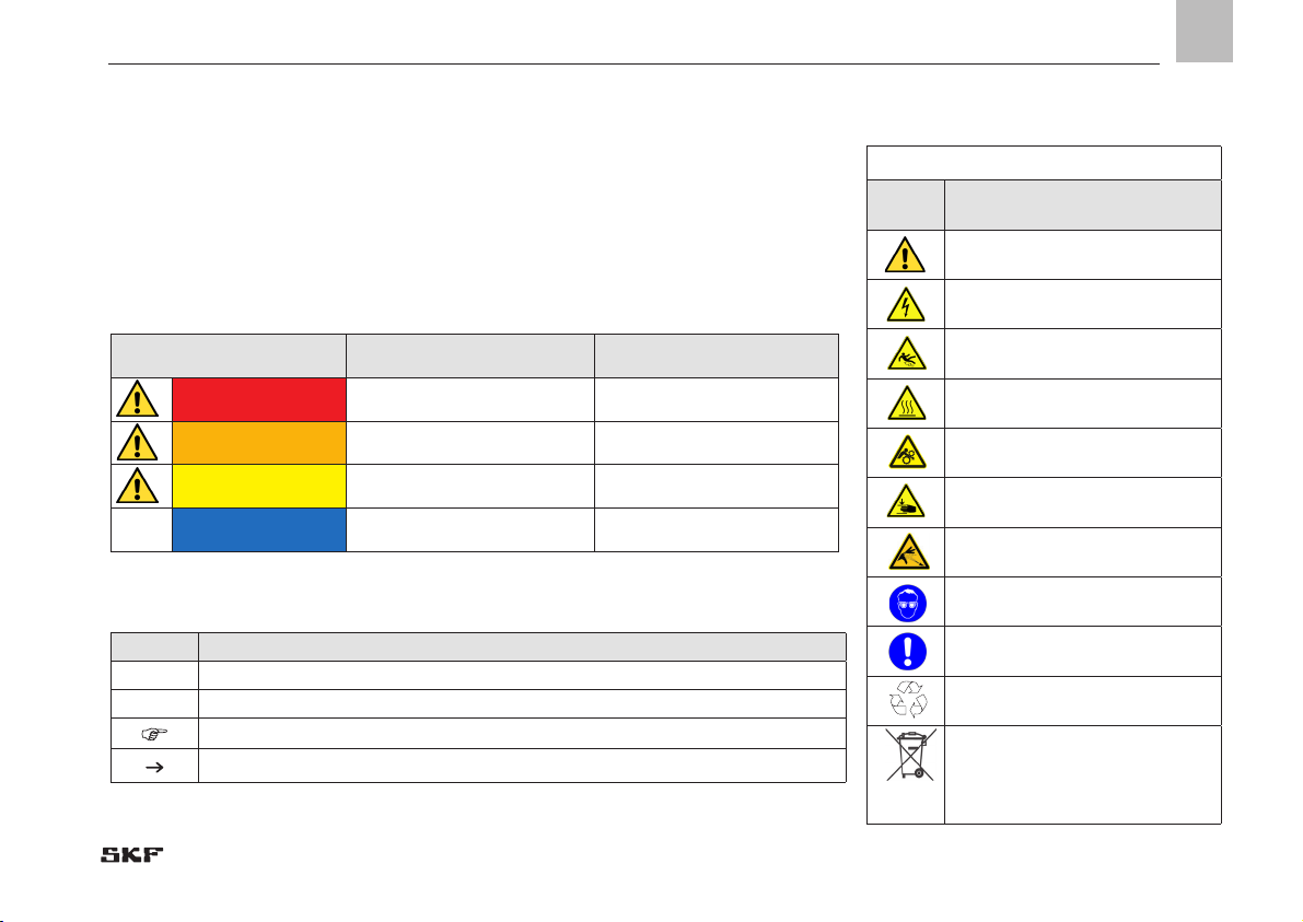
Explanation of symbols and signs ...............................................................5
1. Safety instructions.........................................................................7
1.1 General safety instructions....................................................................7
1.2 General behaviour when handling the product...................................7
1.3 Qualified technical personnel ................................................................8
1.4 Electric current hazard........................................................................... 9
1.5 System pressure hazard ........................................................................9
1.6 Operation.................................................................................................9
1.7 Assembly, maintenance, malfunctions, modification, shutdown,
disposal ..................................................................................................10
1.8 Intended use..........................................................................................10
1.9 Foreseeable misuse..............................................................................11
1.10 Disclaimer of liability.............................................................................11
1.11 Other applicable documents................................................................11
1.12 Residual risks ........................................................................................12
2. Lubricants................................................................................... 14
2.1 General information ............................................................................14
2.2 Selection of lubricants..........................................................................14
2.3 Approved lubricants..............................................................................15
2.4 Lubricants and the environment.........................................................16
3. Overview, functional description ................................................ 17
4. Technical data ............................................................................. 20
4.1 General technical data..........................................................................20
4.2 Notes related to the type identification plate.....................................21
4.3 Notes related to the CE marking .........................................................21
4.4 Limit switch............................................................................................22
4.5 Proximity switch....................................................................................23
5. Delivery, returns, and storage .................................................... 24
5.1 Delivery..................................................................................................24
5.2 Returns .................................................................................................24
5.3 Storage...................................................................................................24
5.4 General notes related to storage.........................................................24
6. Installation.................................................................................. 25
6.1 General information .............................................................................25
6.2 Attachment............................................................................................25
6.3 Electrical connection ............................................................................26
7. Start-up...................................................................................... 27
8. Operation, shutdown and disposal ............................................. 28
8.1 Temporary shutdown ...........................................................................28
8.2 Shutdown and disposal........................................................................28
9. Maintenance, cleaning and repair .............................................. 29
9.1 General information .............................................................................29
9.2 Maintenance..........................................................................................29
9.3 Cleaning .................................................................................................29
9.4 Repair.....................................................................................................29
10. Troubleshooting.......................................................................... 30
11. Spare parts................................................................................. 31
12. Dimensional drawings ................................................................ 34

5
EN
Explanation of symbols and signs
Symbols
Symbol Meaning
General warning
Electrical component hazard,
electrical shock hazard
Slipping hazard
Hazard from hot surfaces
Hazard from unintentional intake
Crushing hazard
Pressure injection hazard
Wear personal protective equip-
ment (goggles)
Note
Environmentally sound disposal
recycling
Environmentally sound disposal
of waste electrical and
electronic equipment
You will find these symbols, which warn of
specific dangers to persons, material assets,
or the environment, next to all safety in-
structions in these operating instructions.
Please read these instructions thor-
oughly and heed the warning and safety
notes. Please observe the warning and
safety notes and exercise particular cau-
tion in these cases. Inform also other users
accordingly.
Symbol Meaning
Prompts an action
Used for itemizing
Refers to other facts, causes, or consequences
Provides additional information within procedures
Warning level Consequence Probability
DANGER Death/ serious injury imminent
WARNING Death/ serious injury possible
CAUTION Minor injury possible
NOTICE Property damage possible

6
EN Explanation of symbols and signs
Abbreviations and conversion factors
Abbreviations
re. regarding oz. Ounce
approx. approx. psi pounds per square inch
°C degrees Celsius rh relative humidity
cu.in cubic inch s second
dB (A) Sound pressure level sq.in. square inch
i.e. that is
etc. et cetera e.g. for example
poss. possibly > greater than
°F degrees Fahrenheit <less than
fl.ou fluid once ±plus or minus
fpsec feet per second Ø Diametre
gal. gallon mph miles per hour
if appl. if applicable rpm revolutions per minute
hp horse power
a.a.r. as a rule
in. inch Conversion factors
incl. including Length 1 mm = 0.03937 in.
K Kelvin Area 1 cm² = 0.155 sq.in
kg Kilogram Volume 1 ml = 0.0352 fl.oz.
kp kilopond 1 l = 2.11416 pints (US)
kW kilowatt Mass 1 kg = 2.205 lbs
l litre 1 g = 0.03527 oz.
lb. pound Density 1 kg/cc = 8.3454 lb./gal(US)
max. maximum 1 kg/cc = 0.03613 lb./cu.in.
min. minimum Force 1 N = 0.10197 kp
min. minute Speed 1 m/s = 3.28084 fpsec.
ml millilitre 1 m/s = 2.23694 mph
ml/d millilitre per day Acceleration 1 m/s² = 3.28084 ft./s²
mm millimetre Pressure 1 bar = 14.5 psi
N Newton Temperature °C = (°F-32) x 5/9
Nm Newtonmeter Output 1 kW = 1.34109 hp

7
1
ENEN
1. Safety instructions
1.1 General safety instructions
The owner must ensure that safety informa-
tion has been read by any persons entrusted
with works on the product or by those per-
sons who supervise or instruct the before-
mentioned group of persons. In addition, the
owner must also ensure that the relevant
personnel are fully familiar with and have un-
derstood the contents of the Instructions.
The instructions must be kept at hand to-
gether with the product for future reference.
The Instructions are part of the product and
must accompany the product when selling it.
The described products were manufactured
according to the state of the art. Risks
may, however, arise from its usage and may
result in harm to persons or damage to ma-
terial assets.
Any malfunctions which may affect safety
must be remedied immediately. In addition to
these Instructions, general statutory regula-
tions and other regulations for accident pre-
vention and environmental protection must
be observed.
1.2 General behaviour when handling the
product
○The product may be used only in aware-
ness of the potential dangers, in proper
technical condition, and according to the
information in these instructions.
○Technical personnel must familiar-
ize themselves with the functions and
operation of the product. The specified
assembly and operating steps and their
sequences must be observed.
○Any unclear points regarding proper
condition or correct assembly/ operation
must be clarified. Operation is prohibited
until issues have been clarified.
○Unauthorized persons must be kept
away.
○Precautionary operational measures and
instructions for the respective work must
be observed.
○Responsibilities for different activities
must be clearly defined and observed.
Uncertainty seriously endangers safety.
○Safety-related protective and emergency
devices must not be removed, modified
or affected otherwise in their function
and are to be checked at regular intervals
for completeness and function.
○If protective and safety equipment has to
be dismantled, it must be reassembled
immediately after finishing the work, and
then checked for correct function.
○Remedy occurring faults in the frame of
responsibilities. Immediately inform your
superior in the case of faults beyond your
competence.
○Wear personal protective equipment
always.
○When handling lubricants, adhere to the
respective safety data sheets.
1. Safety instructions

8
ENEN
1.3 Qualied technical personnel
Only qualified technical personnel may in-
stall, operate, maintain, and repair the prod-
ucts described in this document.
Qualified technical personnel are persons
who have been trained, assigned, and in-
structed by the operator of the final product.
Such persons are familiar with the relevant
standards, rules, accident prevention regu-
lations, and assembly conditions as a result
of their training, experience, and instruction.
They are qualified to carry out the required
activities and in doing so recognize and
avoid any potential hazards. The definition
of qualified personnel and the prohibition
against employing non-qualified personnel
are laid down in DIN VDE 0105 and IEC 364.
Relevant country-specific definitions of
qualified technical personnel apply for coun-
tries outside the scope of DIN VDE 0105 or
IEC 364.
The core principles of these country-specific
qualification requirements for technical
personnel cannot be below those of the two
standards mentioned above.
The operator of the final product is re-
sponsible for assigning tasks and areas of
responsibility and for the responsibility and
monitoring of the personnel. These areas
must be precisely specified by the operator.
The personnel must be trained and in-
structed if they do not possess the required
knowledge.
Product training can also be performed by
SKF in exchange for costs incurred.
1. Safety instructions

9
1
ENEN
1.4 Electric current hazard
WARNING
Electric shock
Working on products not discon-
nected from the power supply may
cause personal injury and damage
to property.
Assembly, maintenance, and repair
works may be performed by quali-
fied and authorized personnel only
on products previously discon-
nected from the power supply.
Electrical connection may be carried out
only by a qualified electrician authorized by
the operator under consideration of the local
connection conditions and legal prescrip-
tions (e.g. VDE/ IEC).
1.5 System pressure hazard
WARNING
System pressure
The product is pressurized during
operation. It must be de-pres-
surized before starting assembly,
maintenance, or repair works.
1.6 Operation
The following must be observed during
commissioning and operation.
○All information within this manual and
the information within the referenced
documents.
○All laws and regulations to be complied
with by the user.
1. Safety instructions

10
ENEN
○All relevant persons (e.g. operating per-
sonnel, supervisors) must be informed
of the activity prior to starting any work.
Precautionary operational measures and
work instructions must be observed.
○Ensure through suitable measures that
movable or detached parts are immobi-
lized during the work and that no limbs
can be caught in between by inadvertent
movements.
○Assemble the product only outside of the
operating range of moving parts, at an
adequate distance from sources of heat
or cold.
○Prior to performing work, the product
and the machine or system in which the
product is or will be integrated must be
depressurized and secured against un-
authorized activation.
○Carry out all works on electrical compo-
nents using voltage insulated tools only.
○Ensure proper grounding of the product.
○Undertake drilling at non-critical, non-
load bearing parts only.
○Other units of the superior machine
must not be damaged or impaired in
their function by the installation of the
product.
○No parts of the centralized lubrication
system may be subjected to torsion,
shear, or bending.
○Use adequate lifting devices when work-
ing with heavy components.
○Repairs may be performed with original
SKF spare parts only.
○Any malfunctions which may affect safety
and functionality must be remedied
immediately.
○Avoid mixing up or wrong assembly of
disassembled parts. Mark these parts
accordingly.
○Modifications or changes to the change-
over device are allowed only upon prior
consultation with the manufacturer.
1.7 Assembly, maintenance, malfunctions, modication, shutdown, disposal 1.8 Intended use
Supply of lubricants within a dual-line sys-
tem following the specifications regarding
the pressure and flow range made in these
Instructions:
The limit values specified in the technical
data, particularly the maximum operat-
ing pressure of 350 bar, must never be
exceeded.
Any other or exceeding use is considered to
be improper use.
For ranges going beyond the specified ones,
the electromotive change-over device type
EM-U3 can be used in combination with
end-of-line pressure switches.
1. Safety instructions

11
1
ENEN
1.9 Foreseeable misuse
Any usage of the product differing from
the aforementioned conditions and stated
purpose is strictly prohibited. Particularly
prohibited are:
○Use in an explosive atmosphere
○Use in continuous operation
○Painting the change-over device.
Remove or tape change-over device
completely before painting the machine.
○Use to feed, forward, or store hazardous
substances and mixtures in accordance
with annex I part 2-5 of the CLP regula-
tion (EC 1272/2008)
○to feed, forward, or store gases, liquefied
gases, dissolved gases, vapours, or fluids
whose vapour pressure exceeds normal
atmospheric pressure (1013 mbar) by
more than 0.5 bar at the maximum per-
missible operating temperature.
1.10 Disclaimer of liability
The manufacturer shall not be held respon-
sible for damages caused by:
○inappropriate usage
○wrong or improper assembly, operation,
adjustment, or programming
○improper or late response to
malfunctions
○unauthorized modification of system
components
○the installation of non-original spare
parts.
1.11 Other applicable documents
In addition to these instructions, the fol-
lowing documents must be observed by the
respective target group:
○Operational instructions and approval
rules
○Instructions of the suppliers of purchased
parts
○Safety data sheet (MSDS) of the lubricant
or material used
○If applicable, project planning documents
and other relevant documents
The operator must supplement these docu-
ments with the relevant applicable national
regulations of the country of use. When sell-
ing or forwarding the product, make sure to
attach these Instructions to it.
1. Safety instructions

12
ENEN
1.12 Residual risks
Residual risks Remedy
Life cycle transport, assembly, start-up, operation, malfunction, troubleshooting, repair, maintenance, shutdown, disposal
Dropping of lifted parts or tools ○No people may remain under suspended loads. Keep unauthorized persons away. Secure suspend-
ed loads using suitable hoisting equipment (e.g. tapes, belts, ropes, etc.).
Falling of parts through insufficient fixing to
the machine
○Fix parts only to machine parts with sufficient load capacity. Observe the weight. Observe the stated
tightening torques. If no tightening torques are stated, the tightening torques are to be applied to
the screw size for 8.8 screws. Literature, see screw manufacturer.
Electrical shock due to defective connection
cable ○Check connection cable for damages.
People slipping due to floor contamination
with spilled or leaked lubricant ○Be careful when connecting or disconnecting hydraulic connections
○Promptly apply suitable binding agents to remove the leaked or spilled lubricant
○Follow the operational instructions for handling lubricants and contaminated parts
Tearing or damaging of lines when installed
on moving machine parts ○If possible, do not install on moving parts. If this cannot be avoided, use flexible hose lines
Ripping out/ damage to lines due to assem-
bly at chafing points or assembly with too
little bending radius
○Use protective pipes or spring coils
Lubricant spraying out due to faulty compo-
nent fitting or line connection
○Use suitable hydraulic screw connections and lines for the stated pressures. Check these prior to
commissioning for correct connection and damage.
1. Safety instructions

13
1
ENEN
Residual risks Remedy
Life cycle transport, assembly, start-up, operation, malfunction, troubleshooting, repair, maintenance, shutdown, disposal
Contamination of the environment with lu-
bricant and wetted parts ○Dispose of the parts following the relevant legal/ operational regulations
1. Safety instructions

14
EN
2. Lubricants
2.1 General information
Intended use is the use of the products to
lubricate bearings and friction points with
lubricants within the physical limits that
can be found in the relevant product docu-
mentation, e.g. operating instructions and
product descriptions, e.g. technical drawings
and catalogues.
Particular attention is called to the fact that
hazardous materials of any kind, especially
those materials classified as hazardous by
CLP Regulation EC 1272/2008 annex I,
part 2-5 may be filled into SKF centralized
lubrication systems and components and
delivered and/ or distributed with such sys-
tems and components only after consulting
with and obtaining written approval from
SKF.
Selection of a lubricant suitable for the
lubrication task is made by the machine or
system manufacturer and/or the operator of
the machine or system in cooperation with
the lubricant supplier.
When selecting a lubricant, the type of
bearings or friction points, the expected
load during operation, and the anticipated
ambient conditions must be taken into ac-
count. All economic and environmental
aspects must also be considered.
NOTICE
Observe the instructions from the machine
manufacturer regarding the lubricants to
be used.
The amount of lubricant required at the
lube point is specified by the bearing or
machine manufacturer. It must be ensured
that the required lubricant volume is pro-
vided to the lubrication point. Otherwise
the lubrication point may not receive ad-
equate lubrication, which can lead to dam-
age and failure of the bearing.
2.2 Selection of lubricants
NOTICE
All products may be used only for their in-
tended purpose and in accordance with the
Instructions.
All products manufactured by SKF are not
admitted for use in combination with gases,
liquefied gases, dissolved gases, vapours, or
fluids whose vapour pressure exceeds nor-
mal atmospheric pressure (1013 mbar) by
more than 0.5 bar at the maximum permis-
sible operating temperature.
Other material which is neither lubricant nor
hazardous substance may be fed only after
consultation with and written approval by
SKF.
SKF considers lubricants to be an element
of system design that must always be
factored when selecting components and
designing a centralized lubrication system.
The lubricating properties of the lubricants
are critically important when making these
selections.
2. Lubricants

15
2
EN
Please contact SKF if you have further
questions regarding lubricants. It is possible
for lubricants to be tested in the company's
laboratory for their suitability for being
pumped in centralized lubrication systems
(e.g. "bleeding").
You can request an overview of the lubricant
tests offered by SKF from the company's
service department.
The product described here can be operated
using lubricants that meet the specifica-
tions in the technical data. Depending on the
product design, these lubricants may be oils,
fluid greases, or greases.
Mineral, synthetic, and/or rapidly biodegrad-
able oils and base oils can be used. Consist-
ency agents and additives may be added
depending on the operating conditions.
Note that in rare cases there may be lubri-
cants whose properties are within permis-
sible limit values but whose other charac-
teristics render them unsuitable for use in
centralized lubrication systems. For exam-
ple, synthetic lubricants may be incompat-
ible with elastomers.
NOTICE
Only lubricants approved for the product
may be used. Unsuitable lubricants can
lead to failure of the product and to prop-
erty damage.
2.3 Approved lubricants
NOTICE
Different lubricants must not be mixed.
Doing so may cause damage and require
costly and complicated cleaning of the
product or lubrication system. It is recom-
mended that an indication of the lubricant
in use be attached to the lubricant reser-
voir in order to prevent accidental mixing
of lubricants.
NOTICE
If required SKF can help customers to
select suitable components for feeding the
selected lubricant and to plan and design
their centralized lubrication system.
2. Lubricants

16
EN
2.4 Lubricants and the environment
WARNING
Risk of slipping and injury
Leaking lubricant is hazardous due
to the risk of slipping and injury.
Seal leaks without delay and re-
move spilled or leaked lubricant.
NOTICE
Lubricants may pollute ground and waters.
Lubricants have to be handled and dis-
posed of properly. Observe the instructions
by the machine manufacturer regarding
the lubricants to be used.
It is important to note that lubricants are
environmentally hazardous, flammable
substances that require special precaution-
ary measures during transport, storage,
and processing. Consult the safety data
sheet from the lubricant manufacturer for
information regarding transport, storage,
processing, and environmental hazards of
the lubricant that will be used.
The safety data sheet of a lubricant may be
requested from the lubricant manufacturer.
2. Lubricants

17
3
2
EN
3. Overview, functional description
In its principle the change-over device corre-
sponds to a pressure-controlled 4/2-way valve.
It alternately dispenses the lubricant fed by the
pump to one of the two main lines while the
other main line is connected to the return line
connection of the pump.
Figures 1 and 2 show a schematic of the
change-over device's function.The lines marked
in black are pressure lines, the white lines are
relief lines:
Pressurized line
Line relieved from
pressure
Control lubricant
The centralized lubrication pump feeds the
lubricant via the pressure line (5) to the change-
over device. The lubricants moves via the pre-
selection piston (2), the change-over piston (1)
and through the main line (7) to the lubricant
metering devices, while the main line (8) is
connected to the reservoir of the centralized lu-
brication pump via the relief line (6) and is thus
depressurized.
Overview Fig. 1
3. Overview, functional description

18
EN
Lubricant pressure actuates the pistons of the
connected dual-line metering devices. The
corresponding lubrication points are provided
with metered lubricant volumes. As soon
as all pistons in the metering devices have
reached their final position, pressure in the
main line (7), in the change-over device and
in the pressure line (5) rises until it overcomes
the force of the spring that presses the valve
piston (4) down. The spring force, and thus
the change-over pressure, can be modified by
means of the adjusting screw (9).
The valve piston (4) releases the connection
between the pressure line (5) and the pre-
selection piston (2) via the switching piston (3).
The pre-selection piston (2) is pushed upward
and connects the pressure line (5) to the upper
front face of the change-over piston (1).
The change-over piston is pushed downward
and opens the connection between the pres-
sure line (5) and the main line (8), while the
main line (7) is connected to the reservoir of
the centralized lubrication pump via the relief
line (6).
The lubricant in main line (7) can now relieve.
When the pressure in the main line (8) rises,
the switching piston (3) is pushed upward.
The described procedure repeats for main
line (8).
Overview Fig. 2
3. Overview, functional description

19
3
EN
Change-over device DU1 is available in 4 different versions:
Type Part no.
DU1-G on base plate 617-28683-1
DU1-GK
with indicator pin mounted on base plate 617-28619-1
DU1-GKS
with indicator pin and limit switch mounted on base plate 617-28620-1
DU1-GKN
with indicator pin and proximity switch mounted on base plate 617-36148-9
3. Overview, functional description

20
EN
4. Technical data
4.1 General technical data
Flow rate 14 dm³/h max.
Change-over pressure min. 140 bar
350 bar max.
Factory setting 170 bar
Operating pressure 350 bar max.
Connection thread G 1/2
Flow media Lubricating oils as of 60 mm²/s at +40°C
Grease up to NLGI class 3 (depending on the operation temperature)
Operation temperature - 20 °C to +80 °C
- 20 °C to +70°C (in combination with proximity switch 234-10812-8)
Installation position any
4. Technical data
Table of contents
Other SKF Industrial Equipment manuals

SKF
SKF Linkoln WS-E Series User manual

SKF
SKF EP1000 Instruction Manual

SKF
SKF PSG Series User manual

SKF
SKF THKI 300 User manual

SKF
SKF TMMA 75H/SET User manual

SKF
SKF TKSA 71 User manual

SKF
SKF TMHP 15/260 User manual

SKF
SKF GVP-S-025-4 User manual

SKF
SKF TMHP 15 Series User manual

SKF
SKF VP Series User manual
Popular Industrial Equipment manuals by other brands

Wizard
Wizard CMC Z1 Getting started manual

KiloVault
KiloVault HAB SCHNEIDER XW PRO UL9540 installation guide

ermengineering
ermengineering APTM-600 Use and maintenance manual

NBK
NBK EPU-210 instruction manual

Kuhse
Kuhse KEA 292 INS operating instructions

Graco
Graco Therm-O-Flow 200 Instructions-parts list