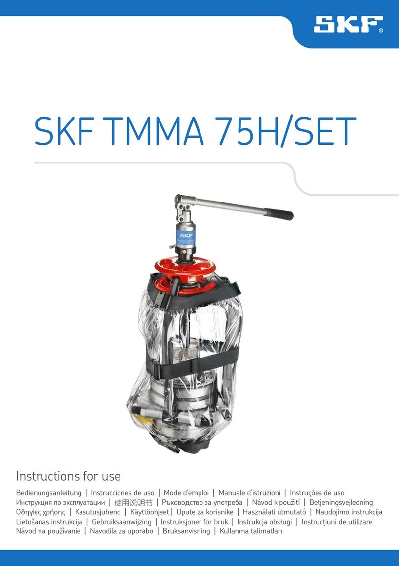
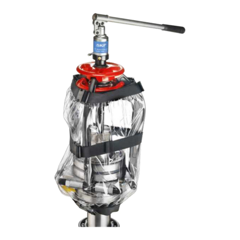
SKF TMHP 15 Series User manual

Instructions for use
Bedienungsanleitung | Instrucciones de uso | Mode d’emploi | Manuale d’istruzioni | Instruções de uso
Инструкция по эксплуатации
|
| Ръководство за употреба | Návod k použití | Betjeningsvejledning
Οδηγίες χρήσης | Kasutusjuhend | Käyttöohjeet | Upute za korisnike | Használati útmutató | Naudojimo instrukcija
Lietošanas instrukcija | Gebruiksaanwijzing | Instruksjoner for bruk | Instrukcja obsługi | Instrucţiuni de utilizare
Návod na používanie | Navodila za uporabo | Bruksanvisning | Kullanma talimatları
SKF TMHP 15/30/50


1
EN English 2
DE Deutsch 7
ES Español 12
FR Français 17
IT Italiano 22
PT Português 27
RU Русский 32
ZH oç37
BG ългарски 42
CS Čeština 47
DA Dansk 52
EL Ελληνικά 57
ET Eesti keel 62
FI Suomi 67
HR Hrvatski 72
HU Magyarul 77
LT Lietuviškai 82
LV Latviešu 87
NL Nederlands 92
NO Norsk 97
PL Polski 102
RO Română 107
SK Slovenčina 112
SL Slovenščina 117
SV Svenska 122
TR Türkçe 127

2EN
Safety recommendations................................................................................................................. 3
EU Declaration of conformity........................................................................................................... 3
UK Declaration of conformity........................................................................................................... 3
1. Description ............................................................................................................................... 4
2. Technical data........................................................................................................................... 4
3. Operating instructions .............................................................................................................. 5
4. Maintenance ............................................................................................................................. 5
4.1 General .........................................................................................................................................................5
4.2 Replacing the oil ...........................................................................................................................................5
4.3 Cleanliness.....................................................................................................................................................5
5. Storage .................................................................................................................................... 5
6. Transportation.......................................................................................................................... 5
7. Spare parts & accessories ......................................................................................................... 6
Table of contents
Original instructions

3EN
Safety recommendations
As high pressures/forces constitute a potential safety
risk, the following instructions must be considered:
• The equipment should only be operated by
trained personnel.
• Do wear proper personal protective gear,
such as eye protection, protective gloves and
safety shoes, when operating the equipment.
• Always follow the operating instructions.
• Check the puller and all accessories carefully
before use.
Never use even slightly damaged components.
• Make sure the force rating of the puller exceeds
calculated maximum withdrawal force.
• Ensure that the puller legs are properly secured
around the workpiece.
Each claw must be fully engaged.
• Make sure the force is equally distributed in all
three arms.
• Make sure all air has been removed from the
hydraulic system, before putting the equipment
under pressure.
• Always use a pressure gauge.
• Always prevent the workpiece/tool from being
projected upon sudden release of pressure
(e.g. by use of retaining nut).
• Never use the equipment above the stated
maximum pressure.
• Use protective goggles.
• Cover the work with a protective blanket or
shield while force being applied.
• Never modify the unit.
• Use original parts only.
• Only use clean, recommended hydraulic oils
(e.g. SKF LHMF 300, LHDF 900 or similar).
• In case of any uncertainties as regards the use
of the puller, contact SKF.
EU Declaration of Conformity
TMHP 15/30/50
We, SKF MPT, Meidoornkade 14, 3992 AE Houten,
The Netherlands herewith declare under our sole
responsibility that the products described in these
instructions for use, are in accordance with the
conditions of the following Directive(s):
MACHINERY DIRECTIVE 2006/42/EC
and are in conformity with the following standards:
EN-ISO 12100-1,
EN-ISO 12100-2,
EN-ISO 14121-1,
EN-ISO 4413
Houten, The Netherlands, October 2022
Guillaume Dubois
Manager Quality and Compliance
UK Declaration of Conformity
TMHP 15/30/50
We, SKF MPT, Meidoornkade 14, 3992 AE Houten,
The Netherlands herewith declare under our sole
responsibility that the products described in these
instructions for use, are in accordance with the
conditions of the following Directive(s):
Supply of Machinery (Safety) Regulations 2008
(2008 No. 1597) and are in conformity with the
following standards:
EN-ISO 12100-1,
EN-ISO 12100-2,
EN-ISO 14121-1,
EN-ISO 4413
The person authorised to compile the technical
documentation on behalf of the manufacturer is
SKF (U.K.) Limited, 2 Canada Close, Banbury,
Oxfordshire, OX16 2RT, GBR.
Houten, The Netherlands, October 2022
Guillaume Dubois
Manager Quality and Compliance
4EN
1. Description
The SKF self-centring hydraulic pullers are specially
designed for extracting large bearings and other
components. To attain the high forces that
then normally are needed, these pullers are
equipped with a hydraulic jack and supplied with
SKF hydraulic pump TMJL 100.
2. Technical data
Description TMHP 15/260
No. of arms 3
Width of grip 195–386 mm (7.7–15.2 in)
Effective arm length 264 mm (10.4 in)
Claw length 37 mm (1.5 in)
Claw height 30 mm (1.2 in)
Piston displacement 100 mm (3.9 in)
Max. pressure 80 MPa (11 600 psi)
Max. force 150 kN (17 US ton)
Weight (without pump*) 31 kg (68 lb)
Description TMHP 30/170 TMHP 30/350 TMHP 30/600
No. of arms 3 3 3
Width of grip 290–500 mm (11.4–19.7 in) 290–500 mm (11.4–19.7 in) 290–500 mm (11.4–19.7 in)
Effective arm length 170 mm (6.7 in) 350 mm (13.7 in) 600 mm (23.6 in)
Claw length 30 mm (1.2 in) 30 mm (1.2 in) 30 mm (1.2 in)
Claw height 35 mm (1.4 in) 35 mm (1.4 in) 35 mm (1.4 in)
Piston displacement 50 mm (2.0 in) 50 mm (2.0 in) 50 mm (2.0 in)
Max. pressure 80 MPa (11 600 psi) 80 MPa (11 600 psi) 80 MPa (11 600 psi)
Max. force 300 kN (34 US ton) 300 kN (34 US ton) 300 kN (34 US ton)
Weight (without pump*) 49 kg (108 lb) 53.5 kg (118 lb) 58 kg (128 lb)
Description TMHP 50/140 TMHP 50/320 TMHP 50/570
No. of arms 3 3 3
Width of grip 310–506 mm (12.2–19.9 in) 310–506 mm (12.2–19.9 in) 310–506 mm (12.2–19.9 in)
Effective arm length 140 mm (5.5 in) 320 mm (12.6 in) 570 mm (22.4 in)
Claw length 32 mm (1.2 in) 32 mm (1.2 in) 32 mm (1.2 in)
Claw height 40 mm (1.6 in) 40 mm (1.6 in) 40 mm (1.6 in)
Piston displacement 40 mm (1.6 in) 40 mm (1.6 in) 40 mm (1.6 in)
Max. pressure 80 MPa (11 600 psi) 80 MPa (11 600 psi) 80 MPa (11 600 psi)
Max. force 500 kN (56 US ton) 500 kN (56 US ton) 500 kN (56 US ton)
Weight (without pump*) 59.5 kg (131 lb) 65 kg (143 lb) 72 kg (159 lb)
Description TMJL 100
*Weight of Hydraulic pump 7 kg (15.4 lb)

5EN
3. Operating instructions
1. Open the puller by pushing the boss forward.
Place the puller on the application and close to
grip by pulling the boss.
Ensure that the puller legs have a good grip on
the workpiece, the claws must be fully engaged.
Tighten the spindle manually.
2. Connect the pump and start injecting oil.
3. The maximum working pressure is 80 MPa
(11 600 psi), which corresponds to the
maximum withdrawal forces.
Never exceed the maximum working pressure.
4. When the maximum axial piston displacement
(see technical data) is reached, the pressure
will rapidly increase. The piston should then
be pressed to its initial position by opening the
release valve and turning the spindle.
Repeat the working cycle until the workpiece is
completely dismounted.
4. Maintenance
4.1 General
Protect the puller against corrosion. Inspect all
puller components on a regular time interval.
4.2 Replacing the oil
When replacing the oil or after maintenance, make
sure no air is trapped in the system.
Only use clean, recommended hydraulic oils.
4.3 Cleanliness
Keep the cylinder clean from dirt and metal particles
in order to avoid excessive wear.
5. Storage
- Dry place without dust, storage in a
well-ventilated dry room.
- Shelf life: max. 36 months.
- Relative humidity: <75 %.
- Storage temperature: +5 … +40 °C.
- No direct sunlight or UV radiation.
- Protection from nearby sources of heat or cold.
6. Transportation
Products should be carried out in the carrying
case provided by SKF in all instances regardless of
distance.
In order to ensure proper protection of the products
during transportation, reloading and storage, they
must be packed in their carrying cases or other
packaging materials that protect the product from
damage and loss.

6EN
7. Spare parts & accessories
Designation Description
TMHP 15-1 Pullerarm - effective arm length 264 mm (10.4 in) (standard)
TMHP 15-2 Pullerarm - effective arm length 344 mm (14.2 in)
TMHP 15-3 Pullerarm - effective arm length 439 mm (17.3 in)
TMHP 15-4 Pullerarm - effective arm length 689 mm (27.1 in)
TMHP 15-5 Spindle and centre nib
TMHP 30-1 Pullerarm - effective arm length 170 mm (6.7 in)
TMHP 30-2 Pullerarm - effective arm length 350 mm (13.7 in)
TMHP 30-3 Pullerarm - effective arm length 600 mm (23.6 in)
TMHP 30-5 Spindle and centre nib
TMHP 50-1 Pullerarm - effective arm length 140 mm (5.5 in)
TMHP 50-2 Pullerarm - effective arm length 320 mm (12.6 in)
TMHP 50-3 Pullerarm - effective arm length 570 mm (22.4 in)
TMHP 50-5 Spindle and centre nib
TMJL 100 Hydraulic pump
-5
-1
-2
-3
-4 TMHP 15 only

7DE
Sicherheitshinweise ........................................................................................................................ 8
CE Konformitätserklärung ............................................................................................................... 8
1. Beschreibung............................................................................................................................ 9
2. Technische daten ...................................................................................................................... 9
3. Bedienungsanleitung .............................................................................................................. 10
4. Wartung ................................................................................................................................. 10
4.1 Allgemeines................................................................................................................................................10
4.2 Ölwechsel.................................................................................................................................................... 10
4.3 Reinhaltung ................................................................................................................................................10
5. Aufbewahrung ........................................................................................................................ 10
6. Transport ............................................................................................................................... 10
7. Ersatzteilliste und zubehör...................................................................................................... 11
Inhalt
Übersetzung der Original-Bedienungsanleitungen

8DE
Sicherheitshinweise
Da hohe Kräfte/hohe Drücke ein Sicherheitsrisiko
darstellen und gefährliche Verletzungen verursachen
können, sind die folgenden Sicherheitshinweise zu
beachten:
• Das Gerät darf nur von geschultem Personal
bedient werden.
• Beim Bedienen der Ausrüstung geeignete
Schutzausrüstung wie beispielsweise
Augenschutz und Schutzhandschuhe tragen.
• Stets die Gebrauchsanweisung/
Betriebsanleitung beachten.
• Vor Inbetriebnahme sind der Abzieher und alle
Zubehörteile sorgfältig zu überprüfen.
Auch nur geringfügig beschädigte Teile, dürfen
auf keinen Fall verwendet werden.
• Der Lagerabzieher muß auf jeden Fall für
größere Kräfte ausgelegt sein als die maximal
notwendige Abziehkraft.
• Die Abzieharme müssen fest und gleichmäßig
am abzuziehenden Bauteil angreifen.
Jeder Haken muß sicher greifen.
• Die Abziehkraft muß gleichmäßig auf die drei
Abzieharme verteilt sein.
• Vor dem Druckaufbau im Gerät muß das
Hydrauliksystem vollständig entlüftet werden.
• Nie ohne Manometer arbeiten.
• Wenn sich das zu demontierende Bauteil oder
Werkzeug gelöst hat, besteht die Gefahr, daß
es schlagartig von seinem Sitz herunterschießt.
Daher Bauteil/Werkzeug immer sichern,
beispielsweise mit einer Sicherungsmutter.
• Das Gerät nie mit höherem Druck als dem
angegebenen Maximaldruck beaufschlagen.
• Immer eine Schutzbrille tragen.
• Solange Kräfte aufgebracht werden,
Arbeitsbereich mit einer Schutzabdeckung oder
Abschirmung absichern.
• Niemals Veränderungen am Gerät vornehmen.
• Nur Original-Ersatzteile verwenden.
• Nur saubere Drucköle nach SKF Empfehlung
verwenden (z.B. SKF LHMF 300, LHDF 900,
o.ä.).
• Wenn Sie Fragen zur Benutzung des Abzichers
haben oder Unsicherheit vorliegt, wenden Sie
sich bitte an SKF.
CE Konformitätserklärung
TMHP 15/30/50
Die SKF MPT, Meidoornkade 14, 3992 AE Houten,
Niederlande erklärt hiermit unter unserer
alleinigen Verantwortung, dass die in dieser
Gebrauchsanweisung beschriebenen Produkte den
folgenden Richtlinien und Normen entsprechen:
MASCHINENRICHTLINIE 2006/42/EC
außerdem stimmen sie mit den folgenden Normen
überein:
EN-ISO 12100-1,
EN-ISO 12100-2,
EN-ISO 14121-1,
EN-ISO 4413
Houten, in den Niederlanden, Oktober 2022
Guillaume Dubois
Manager Quality and Compliance
9DE
1. Beschreibung
Die SKF-Schwerlast-Hakenabzieher wurden
speziell für das Abziehen großer Lager oder anderer
Komponenten entworfen.
Um die normalerweise dafür erforderlichen hohen
Kräfte zu erhalten, sind diese Abzieher mit einer
hydraulischen Winde ausgestattet und mit einer
SKF-Handpumpe TMJL 100 versehen.
2. Technische daten
Beschreibung TMHP 15/260
Zahl der Arme 3
Klemmbreite 195–386 mm
Effektive Schenkellänge 264 mm
Hakenlänge 37 mm
Hakentiefe 30 mm
Hubvolumen 100 mm
Höchstdruck 80 MPa
Höchstkraft 150 kN
Gewicht (without pump*) 31 kg
Beschreibung TMHP 30/170 TMHP 30/350 TMHP 30/600
Zahl der Arme 3 3 3
Klemmbreite 290–500 mm 290–500 mm 290–500 mm
Effektive Schenkellänge 170 mm 350 mm 600 mm
Hakenlänge 30 mm 30 mm 30 mm
Hakentiefe 35 mm 35 mm 35 mm
Hubvolumen 50 mm 50 mm 50 mm
Höchstdruck 80 MPa 80 MPa 80 MPa
Höchstkraft 300 kN 300 kN 300 kN
Gewicht (without pump*) 49 kg 53.5 kg 58 kg
Beschreibung TMHP 50/140 TMHP 50/320 TMHP 50/570
Zahl der Arme 3 3 3
Klemmbreite 310–506 mm 310–506 mm 310–506 mm
Effektive Schenkellänge 140 mm 320 mm 570 mm
Hakenlänge 32 mm 32 mm 32 mm
Hakentiefe 40 mm 40 mm 40 mm
Hubvolumen 40 mm 40 mm 40 mm
Höchstdruck 80 MPa 80 MPa 80 MPa
Höchstkraft 500 kN 500 kN 500 kN
Gewicht (without pump*) 59.5 kg 65 kg 72 kg
Beschreibung TMJL 100
*Weight of Hydraulic pump 7 kg

10 DE
3. Bedienungsanleitung
1. Den Abzieher durch Drücken der Nabe nach
vorne öffnen. Den Abzieher auf die betreffende
Anwendung setzen und durch Ziehen der Nabe
zum Greifen schließen.
Darauf achten, daß die Abzieherarme das
Werkstück gut festklemmen, die Haken müssen
vollständig eingerückt sein. Die Spindel von
Hand festziehen.
2. Die Pumpe anschließen und mit der
Öldruckaufbau beginnen.
3. Der maximale Arbeitsdruck beträgt 80 MPa,
was den maximalen Abziehkräften entspricht.
Den Höchstarbeitsdruck niemals überschreiten.
4. Wenn das maximale axiale Hubvolumen
erreicht wird (siehe technische Daten), steigt
der Druck schnell an. Der Kolben sollte dann
durch Öffnen des Überdruckventils und Drehen
der Spindel in seine Ausgangsposition gedrückt
werden. Den Arbeitszyklus solange wiederholen,
bis das Werkstück komplett demontiert ist.
4. Wartung
4.1 Allgemeines
Den Abzieher vor Korrosion schützen.
Alle Abzieherteile in regelmäßigen Abständen
kontrollieren.
4.2 Ölwechsel
Beim Ölwechsel oder nach Wartungsarbeiten ist
darauf zu achten, daß sich keine Luft mehr im
System befindet. Nur sauberes, empfohlenes
Hydrauliköl verwenden.
4.3 Reinhaltung
Um übermäßigen Verschleiß zu vermeiden, sollte
der Zylinder frei von Schmutz und Metallteilchen
gehalten werden.
5. Aufbewahrung
Trockene und staubfreie Aufbewahrung in einem gut
belüfteten Raum
• Lagerbeständigkeit: max. 36 Monate
• Relative Luftfeuchtigkeit: < 75 %
• Lagertemperatur: +5 bis +40 °C
• Keine direkte Sonneneinstrahlung oder
UV-Strahlung
• Schutz vor Wärme- bzw. Kältequellen
6. Transport
Bei sämtlichen Transportmitteln und Entfernungen
hat der Transport im Behälter des Herstellers zu
erfolgen.
Um die Sicherheit der Produkte beim Transport,
Umladen und Aufbewahren der Produkte zu
gewährleisten, müssen diese in Behälter, andere
Komponenten und Materialien verpackt sein, die die
Produkte vor Beschädigung und Verlust schützen.

11DE
7. Ersatzteilliste und zubehör
Kurzzeichen Beschreibung
TMHP 15-1 Abzieherarm - Effektive Schenkellänge 264 mm (Standard)
TMHP 15-2 Abzieherarm - Effektive Schenkellänge 344 mm
TMHP 15-3 Abzieherarm - Effektive Schenkellänge 439 mm
TMHP 15-4 Abzieherarm - Effektive Schenkellänge 689 mm
TMHP 15-5 Spindel und Zentrierspitze
TMHP 30-1 Abzieherarm - Effektive Schenkellänge 170 mm
TMHP 30-2 Abzieherarm - Effektive Schenkellänge 350 mm
TMHP 30-3 Abzieherarm - Effektive Schenkellänge 600 mm
TMHP 30-5 Spindel und Zentrierspitze
TMHP 50-1 Abzieherarm - Effektive Schenkellänge 140 mm
TMHP 50-2 Abzieherarm - Effektive Schenkellänge 320 mm
TMHP 50-3 Abzieherarm - Effektive Schenkellänge 570 mm
TMHP 50-5 Spindel und Zentrierspitze
TMJL 100 Handpumpe
-5
-1
-2
-3
-4 TMHP 15 only

12 ES
Recomendaciones de seguridad..................................................................................................... 13
Declaración de conformidad CE ..................................................................................................... 13
1. Descripción............................................................................................................................. 14
2. Datos técnicos......................................................................................................................... 14
3. Instrucciones de funcionamiento ............................................................................................. 15
4. Mantenimiento........................................................................................................................ 15
4.1 Generalidades ............................................................................................................................................15
4.2 Cambio de aceite ....................................................................................................................................... 15
4.3 Limpieza......................................................................................................................................................15
5. Almacenamiento ..................................................................................................................... 15
6. Transporte.............................................................................................................................. 15
7. Piezas de repuesto & accesorios.............................................................................................. 16
Índice
Traducción de las instrucciones originales

13ES
Recomendaciones de seguridad
Como las altas presiones/fuerzas constituyen un
riesgo potencial para la seguridad, las siguientes
instrucciones deben ser consideradas:
• Los equipos sólo deben ser manipulados por
personal cualificado.
• Utilice equipos de protección personal
adecuados, como gafas de protección y guantes
protectores, al manejar el equipo.
• Siga siempre las instrucciones de
funcionamiento.
• Compruebe cuidadosamente el extractor y
todos los accesorios antes de usarlos.
No use nunca componentes dañados, ni
siquiera ligeramente dañados.
• Asegúrese de que la fuerza de tiro del extractor
es superior a la máxima fuerza necesaria de
extracción.
• Asegúrese de que las garras del extractor
quedan correctamente fijadas alrededor de la
pieza de trabajo. Cada patilla o uña debe estar
completamente enganchada.
• Asegúrese de que la fuerza de tiro se reparta
por igual para las 3 garras.
• Asegúrese de que todo el aire ha sido eliminado
del sistema hidráulico antes de poner el equipo
bajo presión.
• Use siempre un manómetro.
• Téngase siempre en cuenta que la pieza de
trabajo/herramienta puede salir súbitamente
proyectada al estar sometida a alta presión
(use una tuerca tope o de retención).
• No use nunca el equipo con presiones
superiores a las presiones máximas
establecidas.
• Use gafas protectoras.
• Cubra la zona de trabajo con una manta
protectora o ponga protecciones mientras se
aplica la fuerza.
• No modifique nunca el equipo.
• Use solamente recambios y piezas originales.
• Use solamente aceites hidráulicos
recomendados y limpios (por ejemplo,
SKF LHMF 300, LHDF 900 o similar).
• En caso de duda en relación con el uso del
extractor, contacte con SKF.
Declaración de conformidad CE
TMHP 15/30/50
SKF MPT, Meidoornkade 14, 3992 AE Houten,
Países Bajos, declara bajo su exclusiva
responsabilidad que los productos descritos en
estas instrucciones de uso observan lo dispuesto
en las condiciones establecidas en la(s) siguiente(s)
Directiva(s):
DIRECTIVA DE MÁQUINAS 2006/42/CE
y cumplen con las siguientes normas:
EN-ISO 12100-1,
EN-ISO 12100-2,
EN-ISO 14121-1,
EN-ISO 4413
Houten, Países Bajos, Octubre de 2022
Guillaume Dubois
Jefe de calidad y cumplimiento

14 ES
1. Descripción
Los extractores hidráulicos autocentradores están
especialmente diseñados para extraer los cojinetes
grandes y otros componentes.
Para obtener las grandes fuerzas que normalmente
se necesitan en estos casos, los extractores están
equipados con un gato hidráulico y se suministran
con la bomba hidráulica de SKF TMJL 100.
2. Datos técnicos
Descripción TMHP 15/260
Nº de brazos 3
Anchura de sujeción 195–386 mm (7.7–15.2 in)
Longitud efectiva de
garras
264 mm (10.4 in)
Longitud de brazo 37 mm (1.5 in)
Altura de las garras 30 mm (1.2 in)
Desplazamiento del
émbolo
100 mm (3.9 in)
Presión máx. 80 MPa (11 600 psi)
Fuerza máx. 150 kN (17 US ton)
Peso (without pump*) 31 kg (68 lb)
Descripción TMHP 30/170 TMHP 30/350 TMHP 30/600
Nº de brazos 3 3 3
Anchura de sujeción 290–500 mm (11.4–19.7 in) 290–500 mm (11.4–19.7 in) 290–500 mm (11.4–19.7 in)
Longitud efectiva de
garras
170 mm (6.7 in) 350 mm (13.7 in) 600 mm (23.6 in)
Longitud de brazo 30 mm (1.2 in) 30 mm (1.2 in) 30 mm (1.2 in)
Altura de las garras 35 mm (1.4 in) 35 mm (1.4 in) 35 mm (1.4 in)
Desplazamiento del
émbolo
50 mm (2.0 in) 50 mm (2.0 in) 50 mm (2.0 in)
Presión máx. 80 MPa (11 600 psi) 80 MPa (11 600 psi) 80 MPa (11 600 psi)
Fuerza máx. 300 kN (34 US ton) 300 kN (34 US ton) 300 kN (34 US ton)
Peso (without pump*) 49 kg (108 lb) 53.5 kg (118 lb) 58 kg (128 lb)
Descripción TMHP 50/140 TMHP 50/320 TMHP 50/570
Nº de brazos 3 3 3
Anchura de sujeción 310–506 mm (12.2–19.9 in) 310–506 mm (12.2–19.9 in) 310–506 mm (12.2–19.9 in)
Longitud efectiva de
garras
140 mm (5.5 in) 320 mm (12.6 in) 570 mm (22.4 in)
Longitud de brazo 32 mm (1.2 in) 32 mm (1.2 in) 32 mm (1.2 in)
Altura de las garras 40 mm (1.6 in) 40 mm (1.6 in) 40 mm (1.6 in)
Desplazamiento del
émbolo
40 mm (1.6 in) 40 mm (1.6 in) 40 mm (1.6 in)
Presión máx. 80 MPa (11 600 psi) 80 MPa (11 600 psi) 80 MPa (11 600 psi)
Fuerza máx. 500 kN (56 US ton) 500 kN (56 US ton) 500 kN (56 US ton)
Peso (without pump*) 59.5 kg (131 lb) 65 kg (143 lb) 72 kg (159 lb)
Descripción TMJL 100
*Weight of Hydraulic pump 7 kg (15.4 lb)

15ES
3. Instrucciones de funcionamiento
1. Abra el extractor empujando el reborde hacia
delante. Coloque el extractor en la aplicación y
ciérrelo para sujetar tirando del reborde.
Asegúrese de que las patas del extractor estén
bien sujetas a la pieza de trabajo, los ganchos
deben estar totalmente enganchados.
Apriete el husillo manualmente.
2. Conecte la bomba y empiece a inyectar aceite.
3. La presión efectiva máxima es de 80 MPa
(11 600 psi), que corresponde a las fuerzas
máximas de retirada. No exceda nunca la
presión efectiva máxima.
4. Cuando se alcanza el desplazamiento máximo
del émbolo axial (véanse los datos técnicos), la
presión aumentará rápidamente.
Entonces se debe presionar el émbolo hacia su
posición inicial abriendo la válvula de descarga y
girando el husillo.
Repita el ciclo de trabajo hasta que se haya
desmontado completamente la pieza.
4. Mantenimiento
4.1 Generalidades
Proteja el extractor contra la corrosión. Inspeccione
todos los componentes del extractor a intervalos de
tiempo regulares.
4.2 Cambio de aceite
Al cambiar el aceite o después de llevar a cabo el
mantenimiento, asegurarse de que no ha quedado
aire en el sistema. Usar sólo aceites hidráulicos,
recomendados y límpios.
4.3 Limpieza
Mantenga el cilindro limpio de suciedad y partículas
metálicas para evitar el desgaste excesivo.
5. Almacenamiento
Lugar seco sin polvo, almacenamiento en una sala
seca y bien ventilada
• Vida útil máx. 36 meses
• Humedad relativa < 75%
• Temperatura de almacenamiento: +5 … +40°C
• Sin luz solar directa ni radiación UV
• Protección contra fuentes de calor o frío
cercanas
6. Transporte
El transporte de los productos se realiza en el
contenedor del fabricante por todos los medios de
transporte a cualquier distancia.
Los productos deben ser embalados en
contenedores y otros componentes y materiales que
protejan el producto de daños y pérdidas, con el fin
de garantizar su seguridad durante el transporte, la
recarga y el almacenamiento.

16 ES
7. Piezas de repuesto & accesorios
Designación Descripción
TMHP 15-1 Brazo extractor - longitud efectiva de garras 264 mm (10.4 in) (estándar)
TMHP 15-2 Brazo extractor - longitud efectiva de garras 344 mm (14.2 in)
TMHP 15-3 Brazo extractor - longitud efectiva de garras 439 mm (17.3 in)
TMHP 15-4 Brazo extractor - longitud efectiva de garras 689 mm (27.1 in)
TMHP 15-5 Husillo y extremidad media
TMHP 30-1 Brazo extractor - longitud efectiva de garras 170 mm (6.7 in)
TMHP 30-2 Brazo extractor - longitud efectiva de garras 350 mm (13.7 in)
TMHP 30-3 Brazo extractor - longitud efectiva de garras 600 mm (23.6 in)
TMHP 30-5 Husillo y extremidad media
TMHP 50-1 Brazo extractor - longitud efectiva de garras mm (5.5 in)
TMHP 50-2 Brazo extractor - longitud efectiva de garras 320 mm (12.6 in)
TMHP 50-3 Brazo extractor - longitud efectiva de garras 570 mm (22.4 in)
TMHP 50-5 Husillo y extremidad media
TMJL 100 Bomba hidraulica
-5
-1
-2
-3
-4 TMHP 15 only

17FR
Recommandations de sécurité....................................................................................................... 18
Déclaration de conformité UE ........................................................................................................ 18
1. Description ............................................................................................................................. 19
2. Caractéristiques techniques..................................................................................................... 19
3. Notice d’emploi ....................................................................................................................... 20
4. Maintenance ........................................................................................................................... 20
4.1 Généralités ................................................................................................................................................. 20
4.2 Vidange d’huile........................................................................................................................................... 20
4.3 Propreté...................................................................................................................................................... 20
5. Stockage................................................................................................................................. 20
6. Transport ............................................................................................................................... 20
7. Pièces de rechange & accessoires ............................................................................................ 21
Table des matières
Traduction extraite du mode d’emploi d’origine

18 FR
Recommandations de sécurité
Les hautes pressions/forces constituant un danger
potentiel, les instructions suivantes doivent être
impérativement prises en considération:
• L’équipement doit être utilisé par une personne
expérimentée.
• Porter l’équipement de protection personnelle
adapté, ainsi une protection oculaire et des
gants de protection, pour utiliser l’équipement.
• Toujours suivre soigneusement le mode
d’emploi.
• Vérifier soigneusement l’extracteur et tous les
accessoires avant utilisation.
Ne jamais utiliser de composants endommagés,
même légèrement.
• S’assurer que la force appliquée sur l’extracteur
n’excède pas la force d’extraction maximale
calculée.
• S’assurer que les griffes de l’extracteur soient
correctement positionnées autour de la pièce à
extraire. S’assurer que les griffes de l’extracteur
soient correctement positionnées autour de la
pièce à extraire.
• S’assurer que la force est bien répartie sur les
trois griffes.
• S’assurer que l’air a été totalement évacué
du système hydraulique, avant de mettre
l’équipement sous pression.
• Un manomètre doit systématiquement être
utilisé.
• Afin d’éviter que la pièce à démonter soit
éjectée, il faut toujours placer une pièce en
butée pour limiter la course de démontage
(un écrou par exemple).
• Ne jamais utiliser l’équipement au-dessus de la
pression maximal indiquée.
• Par mesure de sécurité, utiliser
systématiquement des lunettes de protection.
• Couvrir le montage avec une couverture de
protection ou un écran protecteur durant
l’application de la force.
• Ne jamais modifier la pièce.
• Utiliser exclusivement des pièces d’origine.
• N’utiliser que des huiles hydrauliques propres et
recommandées (SKF LHMF 300, LHDF 900 ou
équivalent).
• En cas de doutes concernant l’utilisation de
l’extracteur, contactez SKF.
Déclaration de conformité UE
TMHP 15/30/50
Nous, SKF MPT, Meidoornkade 14,
3992 AE Houten, Pays-Bas déclarons sous notre
responsabilité que les produits décrits dans ces
instructions d’utilisation sont conformes aux
conditions de la ou des directive(s) :
DIRECTIVE MACHINES 2006/42/EC
et sont en conformité avec les normes suivantes :
EN-ISO 12100-1,
EN-ISO 12100-2,
EN-ISO 14121-1,
EN-ISO 4413
Houten, Pays-Bas, Octobre 2022
Guillaume Dubois
Responsable Qualité et Conformité
Other manuals for TMHP 15 Series
1
This manual suits for next models
2
Table of contents
Languages:
Other SKF Industrial Equipment manuals

SKF
SKF LINCOLN SP/SMB3 Series User manual

SKF
SKF TMHP 15/260 User manual

SKF
SKF TKSA 71 User manual

SKF
SKF SMBM-X User manual

SKF
SKF PSG Series User manual

SKF
SKF MonoFlex B Series User manual

SKF
SKF MonoFlex OI-AL-SR User manual

SKF
SKF TKBA 10 User manual

SKF
SKF THKI 300 User manual

SKF
SKF Linkoln WS-E Series User manual