SKF LAHD 500 User manual

SKF LAHD 500-1000
Instructions for use
Mode d’emploi
Bedienungsanleitung
Instrucciones de uso
Manuale d’istruzioni
Instruções de uso
使用说明书
Инструкция по эксплуатации


English
English 2
Français
Français 9
Deutsch
Deutsch 15
Español
Español 21
Italiano
Italiano 27
Português
Português 33
中文
中文39
Русский
Русский 45


3SKF LAHD 500-1000
1. Application .......................................................................................................4
2. Description.......................................................................................................4
3. Technical data ..................................................................................................5
4. Instructions for use ..........................................................................................6
4.1 Installation ...................................................................................................................... 6
5. Maintenance and trouble shooting....................................................................8
5.1 Maintenance................................................................................................................... 8
5.2 Trouble shooting............................................................................................................ 8
Table of contents
Original instructions
English

4 SKF LAHD 500-1000
1. Application
The SKF Oil levellers, type LAHD, are designed for automatic adjustment of the optimal
oil lubrication level within a bearing housing, gearbox, crankcase or similar oil bath
application. It effectively solves the problem of adjusting the correct oil level during running
conditions rather than during standstill.
Furthermore, it will automatically compensate for oil leakage and offers the possibility for
visual inspection of the oil level. The oil leveller will not compensate if the oil level is too
high.
2. Description
The oil leveller basically consists of two communicating oil reservoirs, one on top of the
other. The lower reservoir is in direct contact with the application and hence its oil level
is the same as the oil level inside the application. Through a ventilation system the lower
reservoir is in direct contact with the ambient air.
The upper reservoir is an airtight container storing replacement oil.
Through its extended neck, which dips into the oil of the lower reservoir, the two reservoirs
are in direct connection with each other. However oil can only flow from the upper to
the lower reservoir once the oil level in the lower reservoir goes below the preset level,
allowing air to flow through the extended neck to the upper reservoir.
Oil inlet
Upper cover
Upper reservoir
Spring loaded valve
Set of gaskets
Extended neck
Lower reservoir Oil level
Fixation nut
Magnetic, drainage plug
Assembly drawing oil leveller

5SKF LAHD 500-1000
3. Technical data
Boundary dimensions
- LAHD 500 Ø 91 mm x 290 mm high (3,6 x 11,4 in)
- LAHD 1000 Ø 122 mm x 290 mm high (4,8 x 11,4 in)
Reservoir volume
- LAHD 500 500 ml (17 fl. oz. US)
- LAHD 1000 1 000 ml (34 fl. oz. US)
Container material Polycarbonate, aluminium
Temperature range permitted - 20 .. 70 °C (-5 .. 160 °F)
Permissible humidity 0 - 100 %
Length of connecting tube 600 mm (2 feet)
Connection thread G 1/2
Tube material Polyurethane
O-ring material NBR - 70 Shore
Gaskets NBR - 80 Shore
6 pieces, 3 pcs 3 x 64,5 x 82,5 mm
2 pcs 2 x 64,5 x 82,5 mm
1 pcs 2 x 62,5 x 82,5 mm
Other material Aluminium, Bronze, Stainless Steel
Suitable oil types Mineral and synthetic oils
English

6 SKF LAHD 500-1000
4. Instructions for use
4.1 Installation
1. Determine the required oil level in the application during operation.
For oil lubricated bearing housings this is normally defined as two millimetres
(0,08 in) above the inner diameter of the outer ring of the bearing. It is however,
strongly advised to check the recommendations from the bearing manufacturer.
Similar recommendations exist for gearboxes and crank shaft casings.
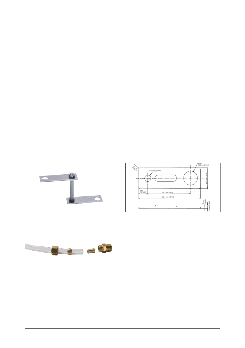
2. Determine the best location for the installation of the support bracket assembly.
The oil leveller must not be more than 60 cm (2 feet, length of plastic tube) from the
application.
3. Adjust the support bracket, which holds the oil leveller to approximately 50 mm
(2 in) below the required oil level.
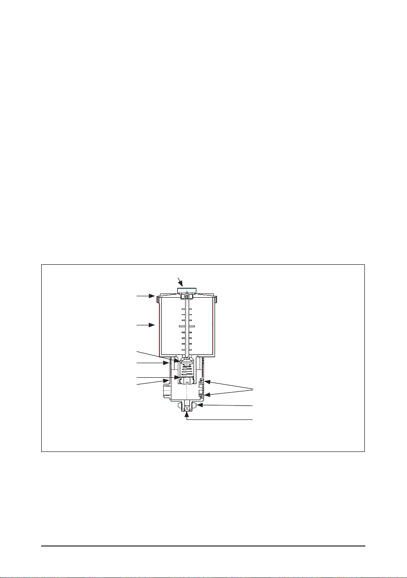
4. Separate the lower and the upper reservoirs from each other.
5. Connect the lower reservoir to the support bracket by means of the fixation nut at the
bottom of the oil leveller.
6. Adjust the height of the oil leveller so that the required oil level is between the two
lines marked on the lower reservoir.
7. Measure and cut the plastic tube to the adequate length.
8. Prepare both ends of the tube with the swivel connectors. Start by sliding the swivel
adapter (with the thread facing outwards) on top of the tube. Insert the copper sleeve
into the tube and slide the copper ring on top of the sleeve.
Bracket assembly Bracket dimensions
Tube & coupling assembly
9. Thread the two connection couplings (G 1/2) onto the oil leveller and the application
and connect the tube. Firmly tighten the swivel adapters.
10. Ensure there are no bends or kinks in the tube preventing the oil to flow freely from
the oil leveller to the application.

7SKF LAHD 500-1000
oil
level
oil
oil oil
level
level
level
Installation
11. Adjust the oil level in the application to the required level and assure that this
corresponds to a level between the two lines marked on the lower reservoir.
If necessary, adjust the height of the lower reservoir by means of the support bracket
screw.
12. Screw the upper reservoir tightly onto the lower reservoir ensuring that the extended
neck is flush with the oil level in the lower reservoir. Use the six rubber gaskets to
obtain the correct height. (Ensure the gasket with the smallest bore remains on top).
13. For high precision applications use the support bracket screw for the fine tuning
(otherwise the accuracy will depend on the thickness of the gaskets).
14. Unscrew the cover of the upper reservoir and fill it with the same oil as used in the
application.
15. Screw back the cover tightly, ensuring that no air can enter into the upper reservoir.
This will also open the valve at the bottom of the upper reservoir and hence connect
the upper and lower reservoir to each other.
16. Start the machine. As the oil in the application will lower due to splashing, oil will flow
from the lower reservoir into the application, exposing the extended neck to open air.
This will allow air to enter the upper reservoir and hence oil to flow down to the lower
reservoir. Once the oil has reached the preset level, air can no longer pass to the
upper reservoir, effectively stopping the flow of oil.
N.B.: During stand-still the oil will stop splashing and the level in the application will rise.
As a consequence the oil level in the oil leveller will also rise above the preset level.
English

8 SKF LAHD 500-1000
5. Maintenance and trouble shooting
5.1 Maintenance
Regularly:
• Check and refill the upper oil reservoir with new, clean oil.
• Clean the oil leveller. For this purpose the lower reservoir is equipped with a drainage
neck with a magnetic plug.
5.2 Trouble shooting
In case of different oil levels in the application and the oil leveller check that:
• The application is provided with a ventilation nipple preventing over/under pressure.
In the case the oil continues to flow from the upper reservoir despite the pre-set level
having been reached:
• Ensure the cover and the oil inlet on the upper reservoir is properly sealed.
In the case of excessive oil consumption check the application for leakage.

9SKF LAHD 500-1000
1. Application .....................................................................................................10
2. Description.....................................................................................................10
3. Caractéristiques techniques............................................................................11
4. Mode d’emploi................................................................................................12
4.1 Installation ....................................................................................................................12
5. Entretien et interventions en cas de panne.....................................................14
5.1 Entretien .......................................................................................................................14
5.2 Interventions en cas de panne...................................................................................14
Table des matières
Traduction extraite du mode d’emploi d’origine
Français

10 SKF LAHD 500-1000
1. Application
Les niveleurs d’huile SKF, de type LAHD, sont conçus pour ajuster automatiquement
le niveau optimal de lubrification en huile d’un logement de roulement, d’une boîte
d’engrenages, d’un carter ou autre application de bain d’huile similaire. Le niveleur
résout le problème de réglage du niveau d’huile correct pendant des conditions de
fonctionnement plutôt qu’en arrêt.
De plus, il compense automatiquement les fuites d’huile et permet de contrôler
visuellement le niveau d’huile. Le niveleur d’huile ne compense pas si le niveau d’huile est
trop élevé.
2. Description
Le niveleur d’huile consiste essentiellement en deux réservoirs d’huile communicants,
disposés l’un sur l’autre. Le réservoir inférieur est en contact direct avec l’application et son
niveau d’huile est par conséquent égal au niveau d’huile de l’application.
Un système de ventilation met le réservoir inférieur en contact avec l’air ambiant.
Le réservoir supérieur est un contenant étanche à l’air qui stocke l’huile de rechange.
Son col prolongé, qui plonge dans l’huile du réservoir inférieur, met les deux réservoirs
en contact direct l’un avec l’autre. Cependant, l’huile ne peut passer du réservoir supérieur
au réservoir inférieur que si le niveau d’huile du réservoir inférieur baisse en deçà du
niveau préréglé, permettant ainsi àà l’air de passer, par le col prolongé, vers le réservoir
supérieur.
Admission d’huile
Couvercle supérieur
Réservoir supérieur
Soupape à ressort
Jeu de joints d’étanchéité
Col prolongé
Réservoir inférieur Ecrou de fixation
Ecrou de fixation
Bouchon de vidange
magnétique
Plan d’assemblage du niveleur d’huile

11SKF LAHD 500-1000
3. Caractéristiques techniques
Dimensions d’encombrement
- LAHD 500 Ø 91 mm x 290 mm de hauteur
- LAHD 1000 Ø 122 mm x 290 mm de hauteur
Volume du réservoir
- LAHD 500 500 ml
- LAHD 1000 1 000 ml
Matériau du réservoir Polycarbonate, aluminium
Plage de températures
admissible - 20 .. 70 °C
Humidité admissible 0 - 100 %
Longueur du tube de 600 mm
raccordement G 1/2
Filetage du raccord Polyuréthanne
Matériau du tube NBR - 70 Shore
Matériau du joint torique NBR - 80 Shore
Joints d’étanchéité 6 unités, 3 unités 3 x 64,5 x 82,5 mm
2 unités 2 x 64,5 x 82,5 mm
1 unités 2 x 62,5 x 82,5 mm
Autres matériaux Aluminium, bronze, acier inoxydable
Types d’huile appropriés huiles minérales et synthétiques
Français

12 SKF LAHD 500-1000
4. Mode d’emploi
4.1 Installation
1. Déterminez le niveau d’huile nécessaire à l’application pendant son fonctionnement.
Pour les logements de roulement lubrifiés à l’huile, ce niveau est normalement fixé à
deux millimètres au-dessus du diamètre interne de la bague intérieure du roulement.
Il est toutefois vivement conseillé de vérifier les recommandations du fabricant du
roulement. Il existe des recommandations pour les boîtes d’engrenage et les carters
de vilebrequin.
2. Déterminez le meilleur endroit pour l’installation de l’assemblage du support. Le
niveleur d’huile ne doit pas être distant de plus de 60 cm (longueur du tube plastique)
par rapport à l’application.
3. Ajustez le support qui retient le niveleur d’huile à environ 50 mm au-dessus du
niveau d’huile requis.
4. Séparez les réservoirs inférieur et supérieur.
5. Fixez le réservoir inférieur au support au moyen des deux écrous de fixation au bas
du niveleur d’huile.
6. Ajustez la hauteur du niveleur d’huile de manière à ce que le niveau d’huile requis se
trouve entre les deux repères indiqués sur le réservoir inférieur.
7. Mesurez et découpez le tube plastique à la longueur adéquate.
8. Préparez les deux extrémités du tube avec les raccords pivotants. Commencez par
glissez l’adaptateur pivotant (son filetage dirigé vers l’extérieur) par le haut du tube.
Insérez le manchon de cuivre dans le tube et glissez la bague de cuivre par le haut du
manchon.
Assemblage du support Dimensions du support
Assemblage du tube et des raccords
9. Vissez les deux raccords (G 1/2) sur le niveleur d’huile et l’application puis raccordez le
tube. Serrez fermement les adaptateurs pivotants.

13SKF LAHD 500-1000
10. Assurez-vous que le tube ne comporte ni courbures ni vrilles empêchant l’huile de
s’écouler librement entre le niveleur d’huile et l’application.
huile
niveau
huile
huile huile
niveau
niveau
niveau
Installation
11. Ajustez le niveau d’huile dans l’application au niveau requis et assurez-vous qu’il
correspond au niveau situé entre les deux repères du réservoir inférieur.
Si nécessaire, ajustez la hauteur du réservoir inférieur à l’aide de la vis du support.
12. Vissez solidement le réservoir supérieur sur le réservoir inférieur en vous assurant
que le col prolongé est de fleur du niveau d’huile du réservoir inférieur. Utilisez les
deux joints étanches en caoutchouc pour obtenir la bonne hauteur.
(Assurez-vous que le joint étanche dont le trou est le plus étroit reste en haut).
13. Pour des applications de haute précision, utilisez la vis du support pour le réglage fin
(sinon la précision dépendra de l’épaisseur des joints d’étanchéité).
14. Dévissez le couvercle du réservoir supérieur et remplissez ce dernier avec la même
huile utilisée dans l’application.
15. Revissez solidement le couvercle et assurez-vous que l’air ne peut pas pénétrer dans
le réservoir supérieur. Cela ouvrira également la soupape située au fond du réservoir
supérieur et donc mettra en communication les réservoirs supérieur et inférieur.
16. Mettez la machine en marche. Comme l’huile présente dans l’application baissera en
raison du barbotage, l’huile passera du réservoir inférieur versà l’application, exposant
ainsi le col prolongé à l’air libre. Cela permettra à l’air de pénétrer dans le réservoir
supérieur et, par conséquent, à l’huile de passer au réservoir inférieur. Une fois que
l’huile aura atteint le niveau préréglé, l’air ne pourra plus passer vers le réservoir
supérieur, arrêtant efficacement l’écoulement d’huile.
N.B. : Lorsque la machine est en arrêt, l’huile s’arrête de barboter et le niveau d’huile dans
l’application augmente. En conséquence de quoi, le niveau d’huile du niveleur d’huile
augmente également au-dessus du niveau préréglé.
Français

14 SKF LAHD 500-1000
5. Entretien et interventions en cas de panne
5.1 Entretien
Régulièrement :
• Contrôlez et ajoutez de l’huile neuve et propre dans le réservoir supérieur.
• Nettoyez le niveleur d’huile. Pour ce faire, le réservoir inférieur est équipé d’un col de
vidange à bouchon magnétique.
5.2 Interventions en cas de panne
Si vous constatez des niveaux d’huile différents dans l’application et le niveleur
d’huile, vérifiez si :
• l’application est dotée d’un embout d’aération empêchant la surpression et la
dépression.
Au cas où l’huile continue de s’écouler du réservoir supérieur bien que le niveau préréglé
ait été atteint :
• assurez-vous que le couvercle et l’admission d’huile du réservoir supérieur sont bien
étanches.
En cas de consommation d’huile excessive, contrôlez l’application quant à la présence
de fuite.

15SKF LAHD 500-1000
1. Anwendung ....................................................................................................16
2. Beschreibung .................................................................................................16
3. Technische Daten ...........................................................................................17
4. Bedienungsanleitung......................................................................................18
4.1 Montage........................................................................................................................18
5. Wartung und Störungsbeseitigung..................................................................20
5.1 Wartung ........................................................................................................................20
5.2 Störungsbeseitigung ...................................................................................................20
Inhalt
Übersetzung der Original-Bedienungsanleitungen
Deutsch

16 SKF LAHD 500-1000
1. Anwendung
Der SKF Ölstandswächter, Typ LAHD, wurde zur automatischen Regulierung des
optimalen Schmierölstands in einem Lagergehäuse, Getriebegehäuse, Kurbelgehäuse
oder einer ähnlichen Ölbadanwendung entworfen. Damit wird das Problem der
Regulierung des korrekten Ölstands während des Betriebs statt während des Stillstands
auf wirksame Weise gelöst. Außerdem kompensiert der Ölstandswächter Ölleckagen
automatisch und bietet die Möglichkeit der Sichtkontrolle des Ölstands. Ein zu hoher
Ölstand kann vom Ölstandswächter nicht kompensiert werden.
2. Beschreibung
Der SKF Ölstandswächter besteht aus zwei kommunizierenden Ölbehältern.
Der untere Behälter ist direkt mit der Anwendung verbunden und hat daher den gleichen
Ölstand wie die Anwendung. Durch ein Lüftungsrohr hat der untere Ölbehälter Kontakt zur
Umgebungsluft.
Der obere Behälter ist luftdicht verschlossen und enthält die Nachfüll-Ölmenge.
Die beiden Behälter sind über einen verlängerten Stutzen, der in das Öl im unteren
Behälter eintaucht, miteinander verbunden. Aus dem oberen Behälter kann nur dann Öl
ausfließen, wenn der Ölstand im unteren Behälter unter das vorher eingestellte Niveau
absinkt, da nur dann Luft über den verlängerten Stutzen in den oberen Behälter gelangen
kann. Der eingestellte Ölstand entspricht daher dem unteren Ende des verlängerten
Stutzens.
Öleinlass
obere Abdeckung
oberer Behälter
Rückschlagventil mit Feder
Dichtungssatz
verlängerter Stutzen
unterer Behälter Ölstand
Befestigungsmuttern
magnetischer Ablassstopfen
Montagezeichnung Ölstandswächter

17SKF LAHD 500-1000
3. Technische Daten
Außenabmessungen:
- LAHD 500 Ø 91 mm x 290 mm Höhe
- LAHD 1000 Ø 122 mm x 290 mm Höhe
Nachfüllvolumen:
- LAHD 500 500 ml
- LAHD 1000 1 000 ml
Behältermaterial Polykarbonat, Aluminium
Umgebungstemperatur - 20 bis 70 °C
Zulässige Luftfeuchte 0 - 100 %
Länge des
Anschlussschlauchs 600 mm
Anschlussgewinde G 1/2
Schlauchmaterial Polyurethan
O-Ringmaterial NBR - 70 Shore
Dichtungen NBR - 80 Shore
6 Stück, 3 Stück 3 x 64,5 x 82,5 mm
2 Stück 2 x 64,5 x 82,5 mm
1 Stück 2 x 62,5 x 82,5 mm
Weitere Werkstoffe Aluminium, Bronze, Edelstahl
Geeignete Öle Mineral- und Syntheseöle
Deutsch

18 SKF LAHD 500-1000
4. Bedienungsanleitung
4.1 Montage
1. Den erforderlichen Ölstand in der Anwendung während des Betriebs bestimmen.
Für ölgeschmierte Lagergehäuse wird dieser normalerweise als zwei Millimeter
über dem inneren Durchmesser des äußeren Rings des Lagers definiert. Es wird
jedoch dringend empfohlen, die Empfehlungen des Lagerherstellers zu beachten.
Entsprechende Empfehlungen gibt es für Getriebegehäuse und Kurbelwellengehäuse.
2. Bestimmen Sie die beste Stelle für die Installation des Stützbügelaufbaus.
Der Ölstandswächter darf nicht mehr als 60 cm (Länge des Plastikschlauchs) von der
Anwendung entfernt sein.
3. Den Stützbügel, der den Ölstandswächter trägt, etwa 50 mm unter dem
erforderlichen Ölstand anbringen.
4. Den oberen und den unteren Behälter voneinander lösen.
5. Den unteren Behälter mit den zwei Befestigungsmuttern, die sich unten am
Ölstandswächter befinden, am Stützbügel befestigen.
6. Die Höhe des Ölstandswächters so anpassen, dass der erforderliche Ölstand zwischen
den zwei Linien liegt, die auf dem unteren Behälter angegeben sind.
7. Den Verbindungsschlauch messen und auf die richtige Länge zuschneiden.
8. Beide Enden des Schlauches mit den Gelenkverbindungen versehen. Dabei erst den
Gelenkadapter (mit nach außen weisendem Gewinde) auf den Schlauch schieben.
Die Kupfer-Laufbuchse in den Schlauch stecken und den Kupferring auf die Buchse
schieben.
Bügelaufbau Bügelabmessungen
Schlauch-und Kupplungsaufbau
9. Die zwei Verbindungskupplungen (G 1/2) auf den Ölstandswächter und die Anwendung
schrauben und den Schlauch anbringen. Die Gelenkadapter fest anziehen.
10. Der Schlauch darf dabei keine Krümmungen und Knicke aufweisen, die den freien
Fluss des Öls vom Ölstandswächter zur Anwendung verhindern.
Other manuals for LAHD 500
1
This manual suits for next models
1
Table of contents
Languages:
Other SKF Measuring Instrument manuals

SKF
SKF LINCOLN VP Series User manual

SKF
SKF PHL FM 10/400 User manual

SKF
SKF Baker AWA-IV Series User manual

SKF
SKF TKRT 25M User manual

SKF
SKF Inspector 400 User manual

SKF
SKF 800030 Product manual

SKF
SKF Baker AWA-IV User manual

SKF
SKF SMD 1B User manual

SKF
SKF VP Series User manual

SKF
SKF TKTL 21 User manual