SKF LINCOLN VP Series User manual

Version 02
951-180-083-EN
03.11.2021
EN
Operating instructions
according to ATEX Directive 2014/34/EU
Progressive metering devices of the series
VP, VPK, VPB EEX
VP VPK VPB

- 2 -
951-180-083-EN
Version 02
EN
Jürgen Kreutzkämper
Manager R&D Germany
Stefan Schürmann
Manager PD Germany South
EU Declaration of Conformity pursuant to ATEX Directive 2014/34/EU, Annex X
The manufacturer, SKF Lubrication Systems Germany GmbH, Walldorf Plant, Heinrich-Hertz-Str. 2-8, DE - 69190 Walldorf, hereby declares under its sole
responsibility conformity of the device
Designation: Progressive metering device, series: VP; VPK und VPB
Part Number: 24-3830-*, 24-3850-*, 24-3810-*, 24-3820-*
Year of manufacture: See type plate
Explosion protection marking:
II 1G IIC T6 Ga /-20...+70°C II 1D IIIC T90°C Da / -20...+70°C Metering device with proximity switch 24-1884-2288
II 2G IIB T4 Gb / -35...+40°C II 2D IIIC T135°C Db / -35...+40°C Metering device with 3/2 directional solenoid valve 24-1254-2219
II 2G IIB T4 Gb / -35...+40°C II 2D IIIC T135°C Db / -35...+40°C Metering device with 2/2 directional solenoid valve 24-1254-2212
II 2G IIB T4 Gb / -20...+40°C II 2D IIIC T135°C Db / -20...+40°C Metering device with proximity switch 24-1884-2288 and with 3/2 directional sole-
noid valve 24-1254-2219
with all essential safety and health requirements of ATEX Directive 2014/34/EU as well as the basic safety and health requirements protection requirements
of Machinery Directive 2006/42/EC specified below at the time of placing on the market.
Furthermore, the following Directives and (harmonized) standards were applied in the applicable areas:
2011/65/EU RoHSII 2014/30/EU Electromagnetic Compatibility
Standard
EN ISO 12100:2010 EN ISO 80079-36:2016 EN 60947-5-6:2000
EN IEC 63000:2018 EN ISO 80079-37:2016 EN 60947-5-2:2007/A1:2012
The device must not be put into service until it has been established that the machinery into which it is to be incorporated is in compliance with the provisions
of ATEX Directive 2014/34/EU, Machinery Directive 2006/42/EC, and all other applicable Directives.
Walldorf, 11/3/2021
EU Declaration of Conformity

- 3 -
951-180-083-EN
Version 02
EN
Masthead
Training
SKF conducts detailed training in order to
enable the maximum safety and efficiency.
SKF recommends taking advantage of this
training. For information, contact the rel-
evant SKF service address.
Copyright
© Copyright SKF
All rights reserved.
Warranty
The instructions do not contain any infor-
mation on the warranty. This can be found in
our General Terms and Conditions.
Disclaimer of liability
The manufacturer shall not be held liable for
damage resulting from:
○Improper usage, assembly,
operation, configuration, maintenance,
repair, intentional or gross negligence, or
accidents
○Use of unsuitable lubricants
○Improper reaction to malfunctions.
○Unauthorized modifications to the
product.
○Use of non-original SKF spare parts
The maximum liability for loss or damage
resulting from the use of our products is
limited to the purchase price. Liability for
indirect damage of any kind is excluded.
Masthead
Manufacturer
SKF Lubrication Systems Germany GmbH
www.skf.com/lubrication
Address of manufacturer plants
Headquarters
Walldorf Plant
Heinrich-Hertz-Str. 2-8
69190 Walldorf
Germany
Tel.: +49 (0) 6227 33-0
Fax: +49 (0) 6227 33-259
Berlin Plant
Motzener Straße 35/37
12277 Berlin
Germany
Tel. +49 (0)30 72002-0
Fax +49 (0)30 72002-111

- 4 -
951-180-083-EN
Version 02
EN Table of contents
Table of contents
Masthead .......................................................................................... 3
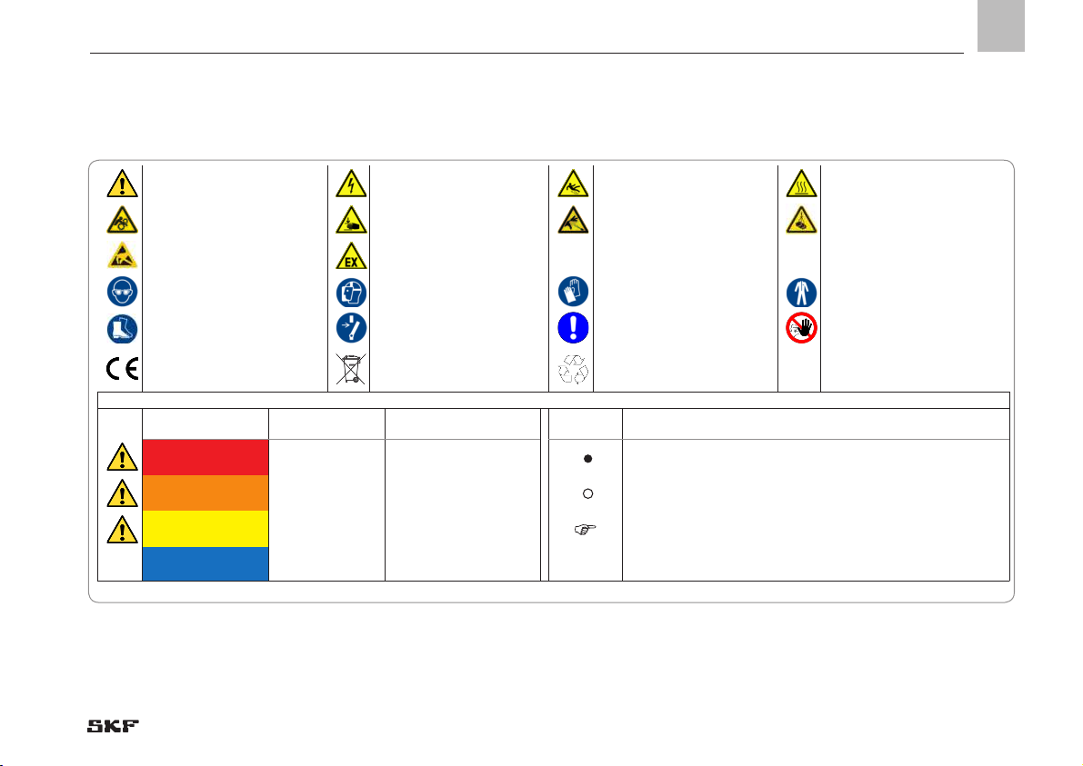
Explanation of symbols and signs ....................................................... 7
1. Safety instructions ................................................................ 9
1.1 General safety instructions ....................................................................9
1.2 General behavior when handling the product .....................................9
1.3 Intended use ..........................................................................................10
1.4 Foreseeable misuse ..............................................................................10
1.5 Painting plastic components ...............................................................11
1.6 Modifications to the product ................................................................11
1.7 Prohibition of certain activities ............................................................11
1.11 Notes on the type plate ........................................................................12
1.12 Note on CE marking .............................................................................12
1.8 Inspections prior to delivery ................................................................12
1.9 Referenced documents ........................................................................12
1.10 Markings on the product ......................................................................12
1.13 Persons authorized to use the product ..............................................13
1.13.1 Operator ...........................................................................................13
1.13.2 Qualified mechanic .........................................................................13
1.13.3 Qualified electrician ......................................................................13
1.16 Operation ...............................................................................................14
1.17 Emergency stop ....................................................................................14
1.18 Transport, assembly, maintenance, malfunction, repair,
shutdown, disposal ...............................................................................14
1.13.4 Specialist in maintenance and servicing in
potentially explosive atmospheres ...............................................14
1.14 Instruction of outside fitters .............................................................14
1.15 Provision of personal protective gear .................................................14
1.19 First start-up, daily start-up ...............................................................16
1.20 Cleaning .................................................................................................16
1.21 Special safety instructions regarding explosion protection .............17
1.22 Nullification of ATEX approval .............................................................19
1.23 Operation in potentially explosive atmospheres ...............................19
1.24 Explosion protection marking .............................................................19
1.25 Obligations of the operator ..................................................................19
1.25.1 Identification of hazards ................................................................19
1.25.2 Explosion protection measures.....................................................19
1.25.3 Provision of necessary information ..............................................20
1.25.4 Duty to provide instruction and training ......................................20
1.26 Residual risks ........................................................................................22
1.27 Residual ATEX risks...............................................................................23
2. Lubricants .......................................................................... 25
2.1 General ...................................................................................................25
2.2 Selection of lubricants ..........................................................................25
2.3 Material compatibility ...........................................................................26
2.4 Aging of lubricants ................................................................................26
2.5 Lubricants in potentially explosive atmospheres ..............................26
3. Overview, functional description .......................................... 27
3.1 Overview of progressive metering devices ........................................27
3.2 ATEX marking according to Directive 2014/34/EU (ATEX) ..............27
3.3 Information on volume data ................................................................28
3.4 Overview of VP progressive metering device series .........................29
3.4.1 Functioning of a VP progressive metering device .......................31
3.5 Overview of VPK progressive metering device series ......................33
3.5.1 Functioning of a VPK progressive metering device ....................35
3.6 Overview of VPB progressive metering device series ......................37
3.6.1 Functioning of a VPB progressive metering device ....................39

- 5 -
951-180-083-EN
Version 02
EN
Table of contents
4. Technical data ..................................................................... 40
4.1 Volume data for VP metering device sections ...................................40
4.1.1 Basic design of VP progressive metering device.........................40
4.1.2 VP progressive metering device with 2/2 directional solenoid
valve for oil and grease, attachment 13 ......................................41
4.1.3 VP progressive metering device with 3/2 directional solenoid
valve for oil and grease, attachment 14 ......................................41
4.1.4 VP progressive metering device with inductive NAMUR sensor . 42
4.2 Volume data for VPK metering device sections .................................43
4.2.1 Basic design of VPK progressive metering device ......................43
4.2.2 VPK progressive metering device with 2/2 directional solenoid
valve for oil and grease, attachment 13 ......................................44
4.2.3 VPK progressive metering device with 3/2 directional solenoid
valve for oil and grease, attachment 14 ......................................44
4.2.4 VPK progressive metering device with inductive NAMUR sensor . 45
4.3 VPB volume data for metering device outlets...................................46
4.3.1 Basic design of VPB progressive metering device ................. 46
4.3.2 VPB progressive metering device with 2/2 directional solenoid
valve for oil and grease, attachment 13 ......................................47
4.3.3 VPB progressive metering device with 3/2 directional solenoid
valve for oil and grease, attachment 14 ......................................47
4.3.4 VPB progressive metering device with inductive NAMUR sensor . 48
5. Delivery, returns, storage .................................................... 49
5.1 Delivery ..................................................................................................49
5.2 Return shipment ...................................................................................49
5.3 Storage ...................................................................................................49
5.3.1 Corrosion protection .......................................................................50
6. Assembly ............................................................................ 51
6.1 Installation information ........................................................................51
6.2 Minimum mounting dimensions.........................................................52
6.3 VP port dimensions, assembly holes, and minimum mounting
dimensions ............................................................................................52
6.3.1 VP in basic design ...........................................................................53
6.3.2 VP tightening torques ....................................................................54
6.3.3 VP progressive metering device with cycle switch,
monitoring type ZY .........................................................................55
6.3.4 VP progressive metering device with inductive NAMUR sensor,
monitoring type ZS (electric monitoring) .....................................55
6.3.5 VP progressive metering device with 2/2 directional solenoid valve 56
6.3.6 VP progressive metering device with 3/2 directional solenoid valve 57
6.3.7 Assembly of the VP progressive metering device .......................57
6.3.8 Connecting outlets on the VPM ....................................................58
6.3.9 Changing VP metering device sections ........................................65
6.4 VPK port dimensions, assembly holes, and minimum
mounting dimensions ..........................................................................65
6.4.1 VPK in basic design ........................................................................65
6.4.2 VPK tightening torques ..................................................................65
6.4.3 VPK progressive metering device with cycle switch, monitoring type ZY ...65
6.4.4 VPK progressive metering device with inductive NAMUR sensor,
monitoring type ZS (electric monitoring) .....................................65
6.4.5 VPK progressive metering device with 2/2 directional solenoid valve 65
6.4.6 VPK progressive metering device with 3/2 directional solenoid valve . 65
6.4.7 Assembly of the VPK progressive metering device .....................65
6.4.8 Consolidation of multiple outlets on the VPK (crossporting) .....66
6.4.9 Changing VPK metering device sections ......................................74

- 6 -
951-180-083-EN
Version 02
EN Table of contents
6.5 VPB port dimensions, assembly holes, and minimum mounting dimensions 7 4
6.5.1 VPB in basic design ........................................................................74
6.5.2 VPB tightening torques ..................................................................74
6.5.3 VPB progressive metering device with cycle switch, monitoring type ZY ...74
6.5.4 VPB progressive metering device with inductive NAMUR sensor,
monitoring type ZS (electric monitoring) .....................................74
6.5.5 VPB progressive metering device with 2/2 directional solenoid valve 74
6.5.6 VPB progressive metering device with 3/2 directional solenoid valve 74
6.5.7 Assembly of the VPB progressive metering device ....................74
6.5.8 Consolidation of multiple outlets on the VPB (crossporting) ....78
6.6 Establishing equipotential bonding ....................................................78
6.7 Electrical connection ...........................................................................78
Connecting the inductive AMUR sensor .......................................................
Connecting directional solenoid valves .........................................................
6.8 Connecting the lubricant line ..............................................................79
6.8.1 Assembly process ...........................................................................80
6.9 Assembly of the lubrication lines using quick disconnect couplings .80
6.10 Lubrication line arrangement .............................................................81
7. First start-up ...................................................................... 83
7.1 Venting a grease progressive system .................................................83
7.2 Venting an oil progressive system ......................................................84
7.3 Inspections before first-time start-up ...............................................85
7.4 Inspections during first-time start-up ...............................................85
8. Operation ........................................................................... 86
9. Cleaning ............................................................................. 86
9.1 Cleaning agents.....................................................................................86
9.2 Exterior cleaning ...................................................................................87
9.3 Interior cleaning ....................................................................................87
10. Maintenance ....................................................................... 88
11. Malfunctions, causes, and remedies ..................................... 89
12. Repairs ............................................................................... 92
12.1 General notes ........................................................................................92
12.2 Replacing inductive NAMUR sensor -see Figure 43 .......................93
13. Shutdown, disposal ............................................................. 94
13.1 Temporary shutdown ...........................................................................94
13.2 Permanent shutdown, disassembly ...................................................94
13.3 Disposal ..................................................................................................94
14. Spare parts ........................................................................ 95
14.1 VP spare parts ......................................................................................95
14.2 VPK spare parts ................................................................................. 103
14.3 VPB spare parts ................................................................................. 109
15. Accessories ....................................................................... 111
15.1 VPB bridge designs (crossporting) .................................................. 111
15.2 VPB check valves ............................................................................... 112
16. Appendix .......................................................................... 113
16.1 Declaration of Conformity proximity switch.................................... 113
16.2 Declaration of Conformity directional solenoid valves .................. 114

- 7 -
951-180-083-EN
Version 02
EN
Explanation of symbols, signs, and abbreviations
Explanation of symbols and signs
General warning Risk of electrical shock Risk of slipping Hot surfaces
Being drawn into machinery Crushing hazard Pressure injection Suspended load
Electrostatic sensitive
components
Potentially explosive
atmosphere
Wear personal protective gear
(goggles)
Wear personal protective
gear (face mask)
Wear personal protective gear
(gloves)
Wear personal protective gear
(protective clothing)
Wear personal protective gear
(protective footwear) Unlock the product General notes Unauthorized persons must be
kept away
CE marking Disposal of waste electrical
and electronic equipment Disposal, recycling
Warning level Consequence Probability Symbol Meaning
DANGER Death, serious
injury Immediate Chronological instructions
WARNING Death, serious
injury Possible Bullet list items
CAUTION Minor
injury Possible Indicates the requirements that must be met for the actions de-
scribed in the following
NOTICE Property damage Possible

- 8 -
951-180-083-EN
Version 02
EN Explanation of symbols, signs, and abbreviations
Abbreviations and conversion factors
re: regarding °C degrees Celsius °F degrees Fahrenheit
approx. approximately K Kelvin Oz. ounce
i.e. that is N Newton fl. oz. Fluid ounce
etc. et cetera h hour in. inch
poss. possibly s second psi pound per square inch
if necessary if necessary d day sq.in. square inch
usually usually Nm Newton meter cu. in. cubic inch
incl. including ml milliliter mph miles per hour
min. minimum ml/d milliliters per day RPM Revolutions per minute
max. maximum ccm cubic centimeter gal. gallon
Min. minute mm millimeter lb. pound
etc. et cetera l liter hp horsepower
e.g. for example db (A) Sound pressure level kp kilopound
kW kilowatt > greater than fpsec feet per second
U Voltage < less than Conversion factors
R Resistance ± plus minus Length 1 mm = 0.03937 in.
I current intensity Ø diameter Area 1 cm² = 0.155 sq.in.
V volt kg kilogram Volume 1 ml = 0.0352 fl.oz.
Wwatt RH relative humidity 1 l = 2.11416 pints (US)
AC alternating current ≈ approximately Ground 1 kg = 2.205 lbs
DC direct current = equal to 1 g = 0.03527 oz.
A ampere % percent Density 1 kg/cm³ = 8.3454 lb./gal(US)
Ah ampere hour ‰ per mil (thousandth) 1 kg/cm³ = 0.03613 lb./cu.in.
Hz Frequency (Hertz) ≥ greater or equal Force 1 N = 0.10197 kp
NC Normally closed contact ≤ less or equal Pressure 1 bar = 14.5 psi
NO Normally open contact mm2square millimeter Temperature °C = (°F-32) x 5/9
rpm Revolutions per minute Power 1 kW = 1.34109 hp
Acceleration 1 m/s² = 3.28084 ft./s²
Speed 1 m/s = 3.28084 fpsec.
1 m/s = 2.23694 mph

1
- 9 -
951-180-083-EN
Version 02
EN
1. Safety instructions
1.1 General safety instructions
○The operator must ensure that the in-
structions are read by all persons tasked
with working on the product or who
supervise or instruct such persons. The
operator must also ensure that the staff
fully understands the content of the in-
structions. Putting the products into op-
eration or operating them without having
read the instructions is prohibited.
○Retain the instructions for further use.
○The products described here were
manufactured in accordance with current
state-of-the-art technology. Risks may,
however, arise from non-compliant us-
age and may result in personal injury or
damage to material assets.
○Any malfunctions which may affect safety
must be remedied immediately. In ad-
dition to these instructions, the statu-
tory regulations for accident prevention
and environmental protection must be
observed.
1.2 General behavior when handling the
product
○The product may only be used in aware-
ness of the potential dangers, in proper
technical condition, and according to the
information in this manual.
○Familiarize yourself with the functions
and operation of the product. The speci-
fied assembly and operating steps and
their sequences must be observed.
○Any unclear points regarding proper
condition or correct assembly/operation
must be clarified. Operation is prohibited
until issues have been clarified.
○Unauthorized persons must be kept
away.
○Wear personal protective equipment.
○All safety regulations and in-house
instructions relevant to the particular
activity must be observed.
○Responsibilities for different activities
must be clearly defined and observed.
Uncertainty seriously endangers safety.
○Protective and safety mechanisms
supplied by the operator must not be
removed, modified, nor disabled dur-
ing operation and must be checked for
proper function and completeness at
regular intervals.
○If protective and safety mechanisms
must be removed, they must be rein-
stalled immediately following conclusion
of work and then inspected for proper
function.
○Any malfunctions that occur must be
resolved according to responsibility. The
supervisor must be notified immediately
in case of malfunctions outside one's in-
dividual scope of responsibility.

- 10 -
951-180-083-EN
Version 02
EN 1. Safety instructions
1.3 Intended use
The ATEX progressive metering devices are
designed for positively driven distribution
of lubricants (oils/greases) in a centralized
lubrication system.
The maximum inlet volumetric flow of the
progressive metering devices is as follows
for the series:
VP 1000 cm3/min
VPK 500 cm3/min
VPB 400 cm3/min.
On all series, the maximum permissible op-
erating pressure for oil is 200 bar and 300
bar for grease.
The inlet and outlet fittings and their con-
necting lines must be designed for these
parameters.
The technical requirements for the in-
stallation of the ATEX VP, VPK, and VPB
progressive feeders are set out in Chapter
6, “Assembly.” These requirements must
be complied with. The same applies to the
technical specifications in Chapter 4, “Tech-
nical data.”
When designing a progressive metering
device, pay attention to the number of cycles
(strokes). On VP and VPK progressive me-
tering devices, the number of cycles should
be kept as low as possible by selecting high-
volume metering device sections. A maxi-
mum value of 200 cycles/min should not be
exceeded. In case of an installation on mov-
ing machine parts or in case of strong vibra-
tions (e.g., on pressing machines), the piston
position of the metering device should not
correspond with the direction of movement
of the machine part.
Only ATEX attachments and monitoring
equipment approved by SKF for the VP;VPK;
VPB metering devices may be installed.
○Never use any part of the centralized
lubrication system as a stand or step or
for climbing.
Any other or additional usage of ATEX VP,
VPK, or VPB progressive metering devices
is deemed non-compliant with the intended
use and could result in damage, malfunc-
tion, or even injury.
1.4 Foreseeable misuse
○Any usage of the product other than as
specified in this manual is strictly prohib-
ited. Particularly prohibited are:
○Use outside the specified operating tem-
perature range
○Use of non-specified equipment
○Use without a pressure relief valve
○Use in continuous operation
○Use in areas with aggressive, corrosive
substances (e.g., high ozone loads)

1
- 11 -
951-180-083-EN
Version 02
EN
1. Safety instructions
○Use in areas with damaging radiation
(e.g., ionizing radiation)
○Use to feed, forward, or store hazardous
substances and mixtures as defined in
Annex I Part 2-5 of the CLP Regulation
(EC 1272/2008) that are marked with
hazard pictograms
GHS01-GHS 09
○Use to feed / forward / store gases,
liquefied gases, dissolved gases, va-
pors, or fluids whose vapor pressure
exceeds normal atmospheric pressure
(1013 mbar) by more than 0.5 bar at
their maximum permissible operating
temperature
○Use in an explosion protection zone
○Use to feed, forward, or store lubricants
with solvents
○Use in potentially explosive gases and
vapors whose ignition temperature is
less than 125% of the maximum surface
temperature
○Use in potentially explosive dusts whose
minimum ignition temperature and glow
temperature are less than 150% of the
maximum surface temperature
○Use in another, more critical explosion
protection zone
○Use with a damaged, missing, or improp-
erly performed subsequent ATEX finish
1.5 Painting plastic components
The painting of all plastic components and
seals of the products described here is
prohibited.
Completely remove or mask affected com-
ponents before painting the main machine.
1.6 Modifications to the product
Unauthorized modifications and changes
can have an unpredictable effect on safety.
Unauthorized modifications and changes
are therefore prohibited.
1.7 Prohibition of certain activities

- 12 -
951-180-083-EN
Version 02
EN 1. Safety instructions
The following activities must be performed
only by employees of the manufacturer or
authorized persons due to possibly unde-
tectable sources of error or due to statutory
requirements:
○Replacement, modifications to the pis-
tons of the metering device elements
1.8 Inspections prior to delivery
The following tests were performed prior to
delivery:
○Safety and functional tests
○
Inspections pursuant to the requirements
of the ATEX Directive.
1.9 Referenced documents
In addition to this manual, the following
documents must be observed by the re-
spective target group:
○Operational instructions, approval rules
○The safety data sheet of the lubricant
used
If applicable:
○Project planning documents
○Instructions from suppliers of purchased
parts
○Instructions for other components for
setting up the centralized lubrication
system
○Other relevant documents for integration
of the product into the main machine,
system
○The explosion protection document of
the operator
1.11 Notes on the type plate
The rating plate provides important data
such as the type designation, order number,
etc.
To avoid loss of this data in case the type
plate becomes illegible, these characteristics
should be entered in the manual.
Material number: 24-38___________ATEX
CE EX _______________________
CE EX __________________________
Series No.________________
1.10 Markings on the product
Equipotential bonding connec-
tions
on the product

1
- 13 -
951-180-083-EN
Version 02
EN
1. Safety instructions
1.12 Note on CE marking
The CE marking is based on the require-
ments of the applied Directives:
○2014/34/EU
Directive for equipment and protective
systems intended for use in potentially
explosive atmospheres (ATEX)
○2014/30/EU
Electromagnetic compatibility
○2011/65/EU
(RoHS II) Directive on the restriction of
the use of certain hazardous substances
in electrical and electronic equipment
Note on Low-Voltage Directive 2014/35/EU
The protection objectives of the Low Voltage
Directive 2014/35/EU are met in accor-
dance with Annex II, No. 1.2.7 of the ATEX
Directive 2014/34/EU.
Note on Pressure Equipment Directive
2014/68/EU
Due to its performance characteristics, the
product does not reach the limit values
defined in Article 4, Paragraph 1, Subpara-
graph (a) (ii) and is excluded from the scope
of Pressure Equipment Directive 2014/68/
EU in accordance with Article 1, Paragraph 2
Subparagraph (f).
1.13 Persons authorized to use
the product
1.13.1 Operator
A person competent due to training, knowl-
edge, and experience to execute the func-
tions and activities associated with normal
operation. This also includes the avoidance
of possible hazards that may arise during
operation.
1.13.2 Qualified mechanic
A person with appropriate technical train-
ing, knowledge, and experience who can
recognize and avoid the hazards that may
occur during transport, assembly, first start-
up, operation, maintenance, repair, and
dismantling.

- 14 -
951-180-083-EN
Version 02
EN 1. Safety instructions
1.13.3 Qualified electrician
A person with appropriate technical training,
knowledge, and experience who can recog-
nize and avoid hazards that may result from
electricity.
1.13.4 Specialist in maintenance and
servicing in potentially explosive
atmospheres
This is a person competent due to qualified
technical education, training, and experi-
ence to recognize risks and possible hazards
when working on the device or subcompo-
nents in potentially explosive atmospheres
and to rectify these by taking suitable ac-
tions. The specialist has knowledge of the
various types of protection, installation
procedures, and explosive atmosphere clas-
sifications. The specialist is familiar with
the rules and requirements relevant to his
or her activity and explosion protection,
especially ATEX Directives 2014/34/EU and
1999/92/EC.
1.14 Instruction of outside fitters
Before commencing work, the operator
must inform outside fitters of the safety
regulations,
applicable accident prevention regulations,
and the functions of the centralized lubrica-
tion system and protective devices.
1.15 Provision of personal protective gear
The operator must provide personal protec-
tive gear appropriate for the location and
intended application. This also includes ESD
clothing and ESD tools for work in a poten-
tially explosive atmosphere.
1.16 Operation
The following must be observed during first
start-up and operation:
○All information within this manual and
all information within the referenced
documents
○All laws and regulations that
the operator must observe
1.17 Emergency stop
Shut down the product in an emergency by:
○Switching off the main machine in which
the product is integrated
○If necessary, pressing the on/off switch
on the main machine

1
- 15 -
951-180-083-EN
Version 02
EN
1. Safety instructions
1.18 Transport, assembly, maintenance, malfunction, repair, shutdown, disposal
limbs can be pinched by unintended
movements.
○Assemble the product only outside the
operating range of moving parts, at an
adequate distance from sources of heat
or cold. Other units of the machine, the
vehicle must not be damaged or impaired
in their function by the installation.
○Dry any wet, slippery surfaces or cover
appropriately.
○Cover hot or cold surfaces appropriately.
○Work on electrical components may be
performed only by qualified electricians.
Note possible waiting times for discharge.
○Work on electrical components may be
performed only in a voltage-free state
and using tools suitable for electrical
work.
○Establish the electrical connection only in
accordance with the valid circuit diagram
and in observance of the relevant regula-
tions and the local electrical operating
conditions.
○Do not touch cables or electrical compo-
nents with wet or moist hands.
○Fuses must not be bridged. Always re-
place defective fuses with fuses of the
same type.
○Ensure proper grounding of the product.
○Drill required holes only on non-critical,
non-load-bearing parts of the opera-
tor's machine/infrastructure. Use existing
boreholes. Do not damage lines or cables
when drilling. Modifications to SKF prod-
ucts are prohibited. This also includes
all drilling, welding, firing, and grinding
work.
○Prior to the start of this work, all relevant
persons must be notified of it. Precau-
tionary operational measures, work
instructions must be observed.
○Transport only with suitable transport
and lifting gear on suitable paths.
○Maintenance and repair work can be
subject to restrictions at low or high tem-
peratures (e.g., altered flow properties
of the lubricant). Maintenance and repair
work should therefore preferably be per-
formed at room temperature.
○Prior to performing work, the product
and the machine in which the product
will be integrated must be de-energized,
depressurized, and secured against un-
authorized activation.
○Take appropriate measures to ensure
that moving, detached parts are im-
mobilized during the work and that no

- 16 -
951-180-083-EN
Version 02
EN 1. Safety instructions
○
Observe any possible wearing spots. Pro-
tect components appropriately.
○All components used must be designed
for:
- The maximum operating pressure
- The maximum/minimum ambient tem-
perature
- The lubricant to be delivered
- The required ATEX zone
- The operating and ambient conditions
at the place of use.
○No parts may be subjected to torsion,
shearing, or bending.
○Check parts for contamination before use
and clean if necessary.
○Lubrication lines should be filled with lu-
bricant prior to assembly. This simplifies
subsequent bleeding of the system.
○Adhere to the specified torques. Use
a calibrated torque wrench when
tightening.
○Use suitable hoisting equipment when
working with heavy parts.
○Avoid mixing up or incorrectly assem-
bling disassembled parts. Label parts.
1.19 First start-up, daily start-up
Ensure that:
○All safety mechanisms are fully present
and functional
○All connections are properly connected
○All parts are correctly installed
○All warning labels on the product are fully
present, visible, and undamaged
○Illegible or missing warning labels are
immediately replaced.

1
- 17 -
951-180-083-EN
Version 02
EN
1. Safety instructions
1.20 Cleaning
○There is a fire hazard from the use of
flammable cleaning agents. Use only
non-flammable cleaning agents that are
suitable for the intended purpose.
○Do not use corrosive cleaning agents.
○Do not use steam-jet equipment or high-
pressure cleaners. This may damage
electrical components.
Observe the IP enclosure rating.
○Mark wet areas accordingly.
1.21 Special safety instructions regarding explosion protection
○Inspect the product at regular intervals
for damage that may present a risk of
ignition.
○The lubricant’s ignition temperature has
to be at least 50 kelvin above the max.
surface temperature of the components.
○Use only tools and clothing approved for
use in potentially explosive atmospheres
(ESD).
○Transport/assembly/repairs and work on
electrical components may be performed
only if it is ensured that there is no explo-
sive atmosphere present.
○Repairs or modifications to explosion-
proof machinery may be performed only
by the manufacturer or a workshop rec-
ognized by a notified body and accepted
by the manufacturer. If the work is not
performed by the manufacturer itself, the
repair must be accepted and approved in
○Always behave so as to avoid explosion
hazards.
○A written work authorization from the
operator is required prior to initiating
work in potentially explosive atmo-
spheres. Unauthorized persons must be
kept away
○There must be no evidence that parts of
the explosion protection are missing or
non-functional. If this is not excluded,
switch off the machine and immediately
notify the supervisor.
○Explosion protection measures must
never be deactivated, changed, or
bypassed.
○The introduction of ignition sources such
as sparks, open flames, and hot surfaces
into potentially explosive atmospheres is
prohibited.

- 18 -
951-180-083-EN
Version 02
EN 1. Safety instructions
writing by an inspector from a recognized
validation organization. The repair is
marked by a repair sign on the machine
containing the following information:
- Date
- Executing company
- Type of repair
- If applicable, mark by expert
○Shipping damage may lead to the loss of
explosion protection. If there is apparent
shipping damage, do not install or put
into operation the product.
○All parts of the grounding concept must
be properly present and connected with
the main machine.
○Handle materials in such a way that no
sparks may arise from tilting, dropping,
slipping, rubbing, or striking. If necessary,
cover materials by appropriate means.
○Never disconnect plug-in connections
under electrical voltage. Secure plug-in
connections against disconnection by
hand using the locking clips provided
○The operator must critically examine
whether operation without an empty
signal results in a new hazard potential
(e.g., due to heating of bearings on the
machine being lubricated to the range
of the ignition temperature in case of
lubrication failure). If this cannot be reli-
ably excluded, an empty signal must be
provided or appropriate organizational
measures taken to monitor the tempera-
ture of the bearings.
○Avoid / immediately remove any accu-
mulated dust. Accumulated dust has a
thermal insulating effect and promotes
the formation of a potentially explosive
atmosphere when agitated/swirled.
○The product must be integrated into the
operator’s lightning protection scheme.
○All parts must be inspected for corrosion
on a regular basis. Replace affected parts
○Junction boxes must be securely closed
and the cable glands properly sealed.
○Any additional electrical monitoring
equipment must be securely connected
and correctly configured.

1
- 19 -
951-180-083-EN
Version 02
EN
1. Safety instructions
1.22 Nullification of ATEX approval
The ATEX approval is nullified by:
○Improper usage
○Unauthorized alterations
○Use of non-original SKF spare/replace-
ment components
○Failure to comply with this manual and
referenced documents
○Use of non-specified equipment
○Failure to observe the prescribed repair
and maintenance intervals
○Operation with a damaged, missing, or
improperly performed subsequent ATEX
finish
1.23 Operation in potentially explosive
atmospheres
Operation is only permitted in compliance
with:
○All information within this manual and
the information within the referenced
documents
○All laws and regulations that the operator
must observe
○The information on explosion protection
according to Directive 1999/92/EC (ATEX
137)
○The ATEX approval
1.24 Explosion protection marking
The explosion protection marking is located
on the Declaration of Conformity and on the
rating plate.
1.25 Obligations of the operator
1.25.1 Identification of hazards
The operator must identify all hazards
resulting from integration into the main
machine as well as the hazards at the ma-
chine’s place of installation. The operator
must take necessary measures for safety
and health protection.
1.25.2 Explosion protection measures
Based on a comprehensive assessment of
the work area, the operator ensures that the
equipment and all installation materials are
suitable for operation in potentially explosive
atmospheres and are assembled, installed,
and operated in such a way that they do not
cause an explosion.

- 20 -
951-180-083-EN
Version 02
EN 1. Safety instructions
If modifications, extensions, and/or conver-
sions are performed in potentially explosive
atmospheres, the operator shall take the
necessary measures to ensure that these
modifications, extensions, or conversions
fulfill the minimum explosion protection
requirements.
The operator
○Documents the measures for explosion
protection
○Marks the potentially explosive areas
○Prepares written operating instructions
○Selects suitable employees
○Provides the employees with adequate
and appropriate instruction regarding
explosion protection
○Employs a release system for hazardous
activities and for those that may become
dangerous in interaction with other work
○Performs required tests and monitoring
○Ensures that only original spare parts
are used
1.25.3 Provision of necessary information
The operator must the relevant required
instructions available to all persons assigned
with operation, repair, and maintenance.
The operator must ensure that the persons
in question have read and understood the
required instructions.
The same applies to all relevant safety data
sheets, operational instructions, accident
protection regulations, and instructions
from suppliers of purchased parts and
consumables.
Depending on the operational organization,
the relevant instructions may need to be
made available to further persons and/or
departments.
This manual suits for next models
2
Table of contents
Other SKF Measuring Instrument manuals

SKF
SKF WEM-200 User manual

SKF
SKF MicroVibe P CMVL 3860-ML User manual

SKF
SKF TKRT 25M User manual

SKF
SKF 15V-090-00102-200 User manual

SKF
SKF VP Series User manual

SKF
SKF TKRT 10 User manual

SKF
SKF Baker AWA-IV Series User manual

SKF
SKF TKRT 21 User manual

SKF
SKF IMx-W User manual

SKF
SKF 800030 Product manual
Popular Measuring Instrument manuals by other brands

TSI Instruments
TSI Instruments Airflow TA500 Series Operation and service manual

Extech Instruments
Extech Instruments MA1500 user manual

Fluidwell
Fluidwell F115-P manual

wtw
wtw pHotoFlex pH quick start guide

PCB Piezotronics
PCB Piezotronics 357B82 Installation and operating manual

Proceq
Proceq Equotip Piccolo 2 Quick reference guide