WI-09-237 Rev. J P/N 701202 3.15.06 SloanLED Page 17 of 22
5.0 PowerLED Mounting and Connection
Mount the transformer directly to the wall, in a vertical position with label at the top (or in
a weatherproof enclosure for outdoor locations) with #8 pan head screws at the top and
bottom of the transformer. The transformer must be mounted in an area that allows for
accessibility after installation and must not be in an area that is adjacent to combustible
materials or that will be allowed to exceed temperatures of 90°C (194°F). After securely
mounting the transformer, remove the front cover to expose the primary and secondary
hook-ups. Have the primary connected by a licensed electrician, following the
instructions on the inside of power supply cover and in accordance with codes.
NOTE ABOUT BOOST TAP HOOK UP: The PowerLED transformer is designed to
reduce primary input voltage (120VAC to 110VAC) to secondary output voltage of
24VAC. It is provided, however, with a boost tap for lower primary voltage applications.
For primary hook up in the range of 120VAC to 110VAC, use the black wire and leave
the blue, boost tap, wire capped. If primary voltage is and will remain below 110VAC,
connect the blue, boost tap, wire to the supply wire and cap the black wire.
WARNING: Whichever option is used, the wire left unconnected must be capped with a
wire nut. It is a live primary voltage potential.
Note: a switch or other disconnect device, which carries the correct rating per UL 48 and
is UL Listed, needs to be wired between the primary power input and the transformer
(see figure 25). This disconnect switch or device must meet the following criteria:
1) Must be provided with each transformer (if multiple transformers are mounted
next to each other and powered on the same primary circuit, one switch can be
used to cut off power to all of them).
2) Must be mounted at or near each transformer.
3) It must have a manual actuator, which shall be protected against mechanical
injury and shall be operable before entering the electrical enclosure of the
transformer.
4) It must be marked with an ON and OFF position.
5) It must have no energized parts accessible to contact when in the OFF position
and not be of the solid-state type.
To hook up the secondary power output (to the LEDStripe product), remove one or more
of the plastic hole plugs in the bottom of the transformer. Insert PLTC wire through hole.
Cut and strip the end. (Strip back about 2” of cable jacket and strip about 3/8” of
insulation off each wire.) Tie a knot in the cable so if it is pulled on from the outside, the
force will not be transmitted to the terminal block. Slide each wire into one output of the
terminal block and secure with the screws supplied. (See figure 24.) When all
secondary outputs are correctly and securely connected, replace the cover and secure
with supplied screws. A licensed, experienced electrician, in accordance with all codes
and regulations should do all electrical connections, both primary and secondary. When
passing through a wall with the transformer output cables, UL Listed, Power Limited Tray
Cable (PLTC), seal the hole in both sides of the wall with silicone. PLTC can be passed
through a wall and be routed inside and outside the building without conduit.
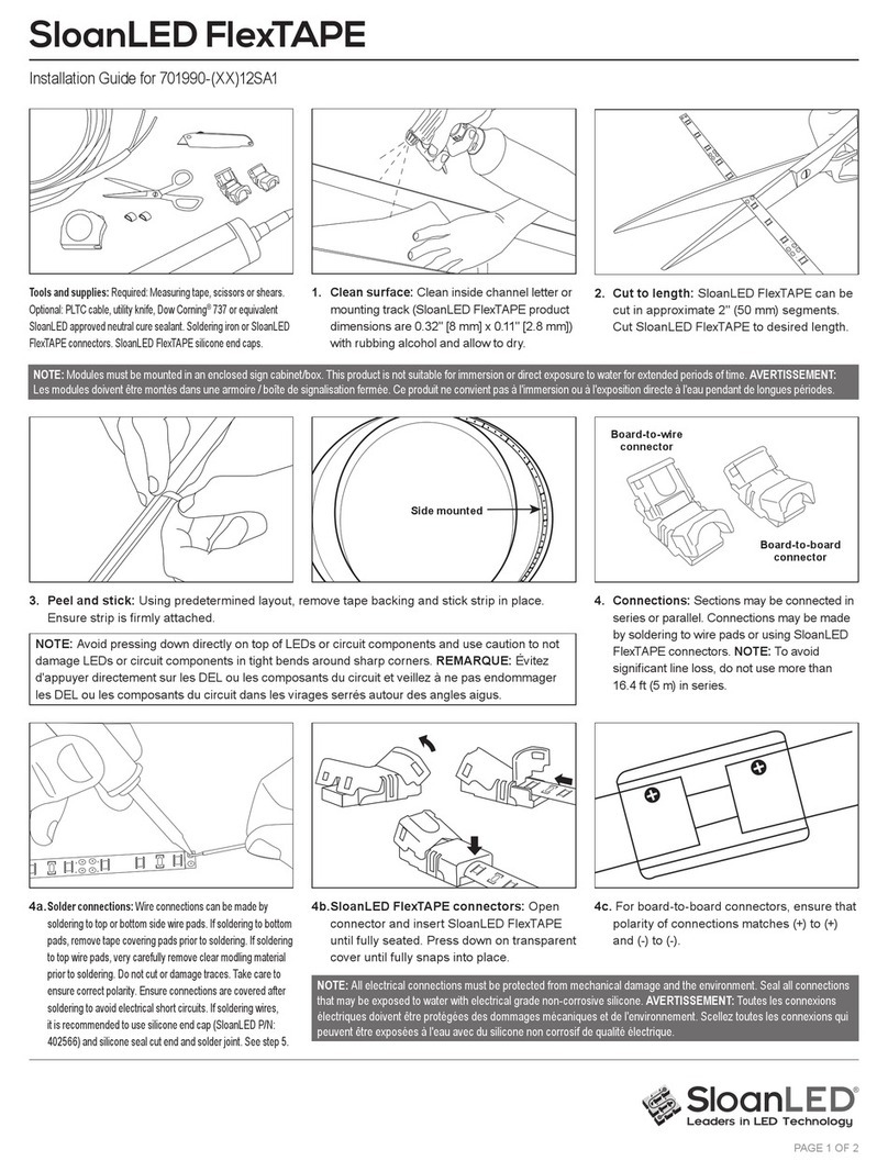
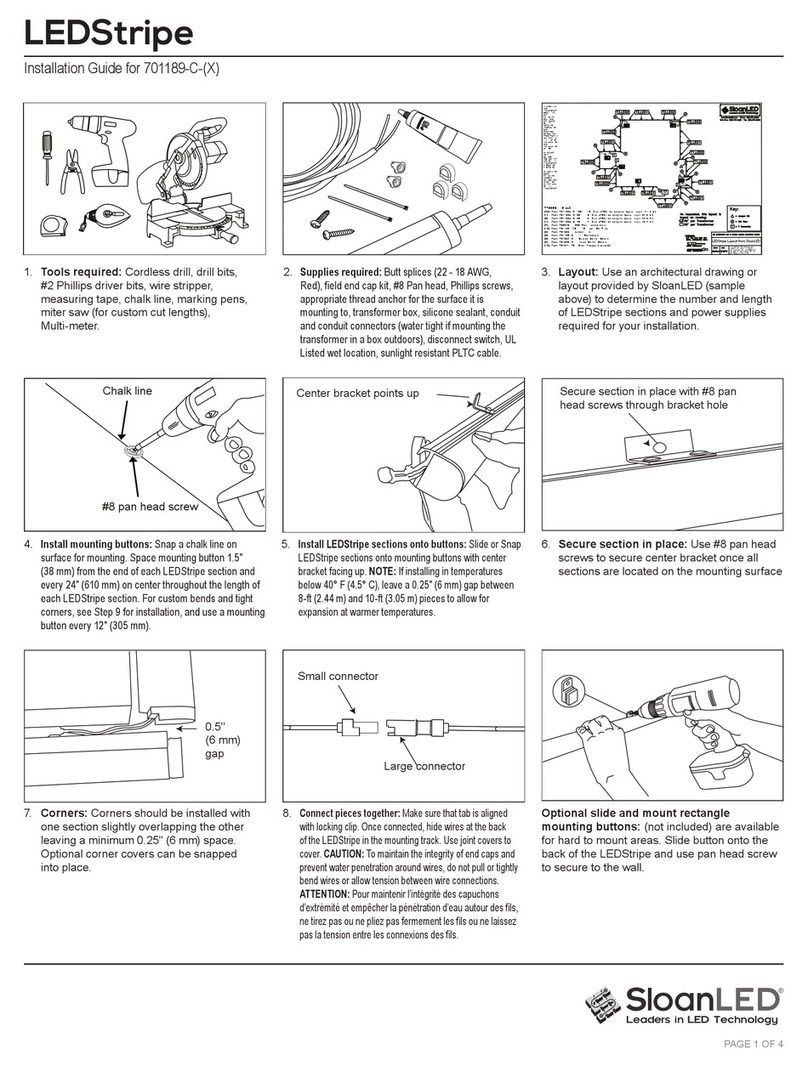
To connect secondary output to LEDStripe product, cut PLTC cable coming from
PowerLED transformer to required length, strip the end, and butt splice connector
assembly to cable. See figure 26. (Use male or female connector as necessary.) The
maximum allowable cable length is 15’ if 18AWG is used or 50’ if 14 AWG is used. After
butt splicing the cable and connector assembly together, seal butt splice with liquid


