manuals.online logo
Brands
  1. Home
  2. •
  3. Brands
  4. •
  5. SloanLED
  6. •
  7. Lighting Equipment
  8. •
  9. SloanLED SignBOX II User manual

SloanLED SignBOX II User manual

IEC_SloanLED_SignBox2_InstallGuide_TDS.pdf
2240 Yates Ave. Commerce, CA 90040
800.CALL IEC
(225.5432)
| Fax 323.803.2019 | www.IECDelivers.com
SIGN LIGHTING GRAPHICS DISPLAY
Excellence in Distribution Since 1946
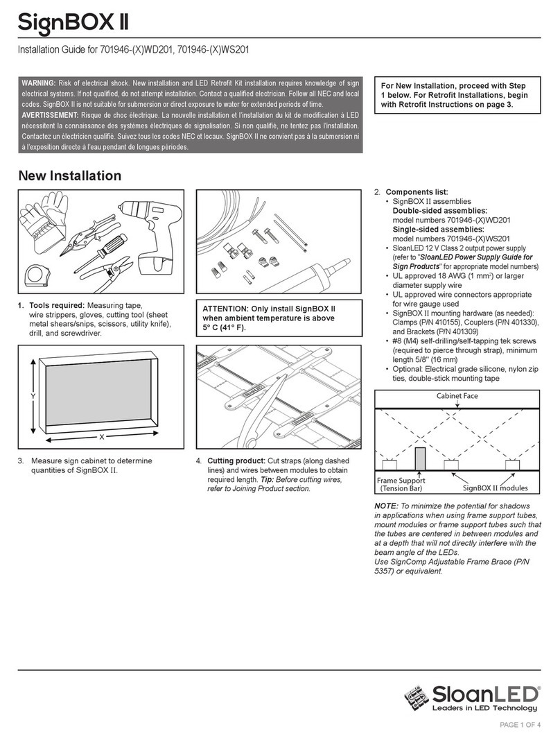
SignBOX™ II
Installation Guide for 701946-XWD201, 701946-XWS201
PAGE 1 OF 3
Tools required: Measuring tape, wire
strippers, gloves, cutting tool (sheet metal
shears/snips, scissors, utility knife), drill,
and screwdriver.
1. Cutting product: Cut straps (along dashed
lines) and wires between modules to obtain
required length. Tip: Before cutting wires,
refer to Joining Product section.
Supplies required: PLTC cable, #8 (M4)
self-drilling/self-tapping tek screws (required
to pierce through strap), minimum length 5/8
in (4 mm), wire nuts, IDC connectors or butt
splices with appropriate safety agency markings.
Optional: cable ties, silicone, double stick tape.
SignBOX II mounting hardware: Clamps (P/N
410155), Couplers (P/N 401330) (as needed),
and Brackets (P/N 401309) (optional).
Installation
RETROFITS: )RU5HWUR¿WVUHIHUWR
installation guide 401302-RET. This guide
can be found on the SloanLED website
under technical info or contact your
SloanLED Customer Service
Representative at 888.747.4LED.
NOTE: All materials removed must
be disposed of in accordance with
applicable local, state and federal laws.
Joining Product
2. When cutting wires between modules,
leaving one side longer will aid in joining
product where needed. If, however, wires
are not long enough for connections, use
either jumper wires or remove a module to
maximize wire length.
3. Use SignBOX II Clamps (P/N 410155) and
SignBOX II Couplers (P/N 401330) to join
shorter pieces of product to required length.
Insert straps from both sides of modules into
clamps (track features facing same direction)
PDNLQJVXUHFODPSVDUHÀXVKDJDLQVW
modules, snap closed (avoid pinching wires),
slide onto couplers, and secure to them with
#8 (M4) tek screws. Connect wires.
1.37
3.25
.10 THICK
SignBOX II Coupler dimensions: 3.25 in x
1.37 in x .10 in (82,5 mm x 34,8 mm x 2,5 mm)
SLO-SB2-MC
SLO-SB2-C
SLO-
SB2-MC SLO-SB2-C
SLO-SB2-EB
2240 Yates Ave. Commerce, CA 90040
800.CALL IEC
(225.5432)
| Fax 323.803.2019 | www.IECDelivers.com
SIGN LIGHTING GRAPHICS DISPLAY
Excellence in Distribution Since 1946
SignBOX™ II
Installation Guide for 701946-XWD201, 701946-XWS201
PAGE 2 OF 3
Mounting Product
4a.Mounting modules with SignBOX II
Clamps (P/N 410155) directly to cabinet:
Insert straps from both sides of module into
clamps (track features facing away from
mounting surface) making sure clamps are
ÀXVKDJDLQVWPRGXOHVQDSFORVHGDYRLG
pinching wires), and secure to cabinet
structure using #8 (M4) tek screws*. Repeat
on opposite end making sure product is taut.
4b.Mounting modules with SignBOX II
Clamps (P/N 410155) using SignBOX II
Brackets (P/N 401309): Install brackets 12
in (305 mm) center-to-center along returns
of cabinet*. Insert straps from both sides of
module into clamps (track features facing
same direction) making sure clamps are
ÀXVKDJDLQVWPRGXOHVQDSFORVHGDYRLG
pinching wires), slide onto bracket, and
secure to it with #8 (M4) tek screws. Repeat
on opposite end making sure product is taut.
4c. Optional mounting in single-sided
cabinet with double stick tape: Using
non-oil based cleaner, clean all mounting
surfaces of sign and bottom of modules for
proper tape adhesion. With double stick
tape on bottom of modules (not included),
mount to back of cabinet. Make sure
product is taut.
Opened Clamp
Structural Support Guidelines for SignBOX II
Vertical mounting: space supports at even intervals, but no further apart than 8 ft (2,4 m).
Horizontal mounting: space supports at even intervals, but no further apart than 4 ft (1,2 m).
Connecting Product to Power Supply
20 ft max 10 ft max
option 1
10 ft max
option 2
20 ft max
option 3
Single-sided option Double-sided options
5. Using electrical connectors with appropriate safety agency markings,
daisy chain product as required and connect to power supply as
shown above. CAUTION! Have a licensed electrician connect primary.
Modules may be connected in series or parallel. End wires of SignBOX
II should be capped and not tied back to power supply.
WARNING check polarity:
All connections must be RED-TO-RED (+) and BLACK-TO-
BLACK (-). Reverse polarity connections may damage the LEDs
and will void product warranty.
* Refer to Density Guidelines to determine SignBOX II product and installation method.
IEC_SloanLED_SignBox2_InstallGuide_TDS.pdf
SLO-SB2-MC SLO-SB2-MC
SLO-SB2-EB
2240 Yates Ave. Commerce, CA 90040
800.CALL IEC
(225.5432)
| Fax 323.803.2019 | www.IECDelivers.com
SIGN LIGHTING GRAPHICS DISPLAY
Excellence in Distribution Since 1946
Customer service and technical support
888.747.4LED (888.747.4533)
SloanLED.com • [email protected]
Europe: Customer service and technical support
+31 (15) 3641569
SloanLED.com • [email protected]
P/N 401302 Rev A 2013-07-18
SignBOX™ II
Installation Guide for 701946-XWD201, 701946-XWS201
PAGE 3 OF 3
12 VDC Power Supply Capacity Table for SignBOX II
Input Output
Power Supply Part # (Each) Nominal Input
Voltage
Input
Current
Power
Output
Output
Current
Maximum modules
single-sided or one leg of
double-sided
Maximum modules
double-sided, both legs
Self Contained 20 701680 120-240 V 0.3 A 20 W 1.5 A 20 10
MODW 60 W (North America) 701507-MODW 120-240 V 1.0 A 60 W 4.5 A 60 30
MODWE 60 W (Europe) 701507-MODWE 100-240 V 1.0 A 60 W 4.5 A 60 30
MOD277 60 W 701507-MOD277 277-347 V 0.5 A 60 W 4.5 A 60 30
All footage based on 90% of rated capacity Power used per foot (Meter) in Watts: 2.7 W (8,9) 5.4 W (17,7)
Extension of Power Supply Leads
If longer lead wire from power supply to LED modules is needed, an extension can be used. Extension should be kept as short as possible, i.e.,
under 15 ft for 18 AWG UL Listed PLTC (4,6 m for 1 mm² PLTC) or under 50 ft for 14 AWG UL Listed PLTC (15,2 m for 2,5 mm² PLTC).
Troubleshooting:
Entire box/cabinet or product
does not light after complete
installation.
&KHFNFRQQHFWLRQIURPSRZHUVXSSO\OHDGWR¿UVWPRGXOH0DNHVXUHSRODULW\RIFRQQHFWLRQVPDGHDWWKHSRZHUVXSSO\OHDGDQG
any jumper wire is correct. Power supply outputs should be connected RED-TO-RED and BLACK-TO-BLACK.
Still does not light.
Check output voltage of power supply using a voltmeter. The output voltage should be DC 12.0 V ± 0.5 V. If there is no output
voltage, have a licensed electrician check input voltage. Make sure power supply is connected correctly and getting primary power.
If power supply is connected properly and getting primary power and there is still no output voltage, try a different power supply.
Still does not light.
If power supply is getting primary power and modules don’t light, there may be a short in the secondary wiring. Check all
connections and cap all loose wires.
The beginning of a strip lights,
but the entire strip does not
light or lights intermittently.
The primary cause of a portion of a strip is not lighting or lighting intermittently is a bad connection or reverse polarity connection
between modules that light and modules that don’t light. Check this connection.
One module does not light, but
all others in the product light.
SignBOX
II
is designed so if one module fails, it will not cause the entire box/cabinet or strip to go out. If one module does not
light, but all others in the product do, replace this module with a new one.
US patents and foreign patents pending
IEC_SloanLED_SignBox2_InstallGuide_TDS.pdf
SLO-PS-12SC
SLO-PS-12C
SLO-PS12C277
SLO-PS-12C

Other SloanLED Lighting Equipment manuals

SloanLED 701946-6WMLP1 User manual

SloanLED

SloanLED 701946-6WMLP1 User manual

SloanLED PosterBOX User manual

SloanLED

SloanLED PosterBOX User manual

SloanLED SignBOX 3 Slim User manual

SloanLED

SloanLED SignBOX 3 Slim User manual

SloanLED PosterBOXID 701946-6WLNP1 User manual

SloanLED

SloanLED PosterBOXID 701946-6WLNP1 User manual

SloanLED PrismBEAM 24V User manual

SloanLED

SloanLED PrismBEAM 24V User manual

SloanLED LEDStripe User manual

SloanLED

SloanLED LEDStripe User manual

SloanLED HighLINER 2 User manual

SloanLED

SloanLED HighLINER 2 User manual

SloanLED PosterBOX Mini User manual

SloanLED

SloanLED PosterBOX Mini User manual

SloanLED FlexTAPE User manual

SloanLED

SloanLED FlexTAPE User manual

SloanLED SignBOX 3 User manual

SloanLED

SloanLED SignBOX 3 User manual

SloanLED 12 V BP LEDStripe User manual

SloanLED

SloanLED 12 V BP LEDStripe User manual

SloanLED PosterBOX Slim User manual

SloanLED

SloanLED PosterBOX Slim User manual
SloanLED Prism User manual

SloanLED

SloanLED Prism User manual

SloanLED LEDStripe User manual

SloanLED

SloanLED LEDStripe User manual

SloanLED PosterBOX3 User manual

SloanLED

SloanLED PosterBOX3 User manual

SloanLED SignBOX II User manual

SloanLED

SloanLED SignBOX II User manual

SloanLED PrismBEAM24 User manual

SloanLED

SloanLED PrismBEAM24 User manual

SloanLED LEDStripe User manual

SloanLED

SloanLED LEDStripe User manual

SloanLED Value-Line 701269-WLX-MB User manual

SloanLED

SloanLED Value-Line 701269-WLX-MB User manual

SloanLED HighLINER Instruction Manual

SloanLED

SloanLED HighLINER Instruction Manual

SloanLED BendLUX 701960-6WS241 User manual

SloanLED

SloanLED BendLUX 701960-6WS241 User manual

SloanLED BendLUX 701960-6WS241 User manual

SloanLED

SloanLED BendLUX 701960-6WS241 User manual

Popular Lighting Equipment manuals by other brands

Access 23089FC installation instructions

Access

Access 23089FC installation instructions

IOTA I-320 instruction manual

IOTA

IOTA I-320 instruction manual

Elation Design Spot 1400E owner's manual

Elation

Elation Design Spot 1400E owner's manual

Saber light ATD-80028 owner's manual

Saber light

Saber light ATD-80028 owner's manual

Solar Sun Rings Solar Sun Ring in Plain Blue manual

Solar Sun Rings

Solar Sun Rings Solar Sun Ring in Plain Blue manual

LED World FA60M50-4M-12V-RGB Important instructions

LED World

LED World FA60M50-4M-12V-RGB Important instructions

DÖRR FX-4555 BC instruction manual

DÖRR

DÖRR FX-4555 BC instruction manual

ENER-J SHA5298 installation guide

ENER-J

ENER-J SHA5298 installation guide

EuroLite LED FL-2200 Flamelight with DMX user manual

EuroLite

EuroLite LED FL-2200 Flamelight with DMX user manual

Lightolier LP-15 Specification sheet

Lightolier

Lightolier LP-15 Specification sheet

Robe Robin Actor 3 Smart White user manual

Robe

Robe Robin Actor 3 Smart White user manual

Hubbell Kim Lighting Lightvault LTV59 installation instructions

Hubbell

Hubbell Kim Lighting Lightvault LTV59 installation instructions

Dextra Lighting OAT quick guide

Dextra Lighting

Dextra Lighting OAT quick guide

LIGMAN QUANTUM 3 QA-50021 installation manual

LIGMAN

LIGMAN QUANTUM 3 QA-50021 installation manual

Steren LAM-820 instruction manual

Steren

Steren LAM-820 instruction manual

Hess LEDIA GL D Installation and operating instructions

Hess

Hess LEDIA GL D Installation and operating instructions

Beghelli Tempesta TA-RMT-LED instructions

Beghelli

Beghelli Tempesta TA-RMT-LED instructions

Event Lighting PIXBAR12x8 user manual

Event Lighting

Event Lighting PIXBAR12x8 user manual

manuals.online logo
manuals.online logoBrands
  • About & Mission
  • Contact us
  • Privacy Policy
  • Terms and Conditions

Copyright 2025 Manuals.Online. All Rights Reserved.