PAGE 2 OF 3
PosterBOX 3
Installation Guide for 701946-6WLRP1, -6WSRP1
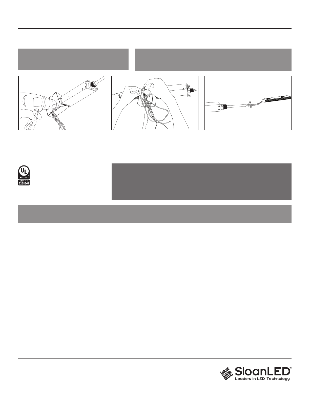
5. Units may be mounted in any orientation
using mounting tabs.
6. Connect primary: CAUTION!
Have a licensed electrician connect primary.
7. Connect to power supply: Using UL Listed
electrical connectors, daisy chain product as
required and connect to power supply.
CAUTION: Luminaire should be positioned so that prolonged staring into
luminaire at a distance closer than 12.7" (322 mm) is not expected.
ATTENTION: Le luminaire doit être placé de manière à ne pas provoquer de
regards prolongés dans le luminaire à une distance inférieure à 322 mm (12.7").
WARNING: Connect Red striped wire of LED modules (+) to Red wire of power supply (+). Connect White wire of LED modules
(-) to Black wire of power supply (-). Reverse polarity connections may damage the LEDs and will void product warranty.
AVERTISSEMENT: Connectez le l rouge des modules LED (+) au l rouge de l'alimentation (+). Connectez le l blanc des modules
LED (-) au l noir de l'alimentation (-). Des connexions inversées peuvent endommager les DEL et annuler la garantie du produit.
Retrot Instructions for Existing Signs
WARNING: Risk of re or electric shock. Install this kit only in host signs that have been identied in the installation instructions, and
where the input rating of the retrot kit does not exceed the input rating of the sign. Installation of this LED retrot kit may involve drilling
or punching of holes into the structure of the sign. Check for enclosed wiring and components to avoid damage to wiring and electrical
parts. AVERTISSEMENT: Risque d’incendie ou de choc électrique. Installez ce kit uniquement sur les panneaux hôtes identiés dans
les instructions d'installation et dans lesquels les caractéristiques nominales d'entrée du kit de modication ne dépassent pas celles du
panneau. L’installation de ce kit d’amélioration des LED peut impliquer de percer ou de percer des trous dans la structure de l’enseigne.
Vériez le câblage et les composants inclus pour éviter d'endommager le câblage et les pièces électriques.
GENERAL PURPOSE
RETROFIT SIGN CONVERSION.
FOR USE ONLY IN ACCORDANCE
WITH KIT INSTRUCTIONS.
KIT IS COMPLETE ONLY WHEN ALL PARTS
REQUIRED BY THE INSTRUCTIONS ARE PRESENT.
CAUTION: Turn o power to sign before inspecting or removing existing light source. Power must remain o while installing LED product.
ATTENTION : Coupez l'alimentation générale du panneau avant d'intervenir ou de retirer la source lumineuse existante. L'alimentation générale doit
être coupée tout au long de l'installation du kit de remplacement en LED.
1. Identify sign to be retrot and ensure branch circuit supplying existing sign are within voltage range for LED power supply.
Refer to components list (page 1) and "24 VDC Power Supply Capacity Chart" (page 3).
2. Remove existing lighting equipment intended to be replaced, such as neon or uorescent, and all power supplies, transformers, or ballasts.
Remove existing neon and all standos to leave an empty sign cabinet. NOTE: All materials removed must be disposed of in accordance with
applicable local, state, and federal laws.
3. If required by local, state, or national electrical code, install a new disconnect switch.
4. Determine suitability and structural integrity of existing sign after removal of existing lighting equipment. If retrot does not require the making
of any new holes, do not make or alter any open holes in an enclosure of wiring or electrical components during kit installation. If existing holes
are present in a wet or outdoor location sign, repair and seal any unused openings in the electrical enclosure.
Openings greater than 0.5" (12.7 mm) diameter require a metal patch secured by screws or rivets and caulked with non-hardening caulk.
Smaller openings may be sealed with non-hardening caulk.
5. Clean inside of sign using non-oil based cleaner. Follow all manufacturer’s instructions and ensure inside of sign is dry before proceeding with
installation. This is an important step for good adhesion of PosterBOX 3 module mounting tape.
6. To populate sign, refer to PosterBOX 3 density guidelines as well as power supply loading chart (page 3) to determine appropriate number of
modules and power supplies. A list of acceptable power supply models is shown in the "24 VDC Power Supply Capacity Chart" (page 3).
7. Follow all instructions on pages 1 and 2 under "New Installation" to properly install LED modules.
8. Connect modules to power supply output as shown on page 2 under "New Installation".
9. Connect power supply input as outlined in power supply installation guide in accordance with local, state and national electrical codes by
qualied personnel. Refer to power supply install guide included with power supply for details.
10. If required, install disconnect switch in accordance with local, state and national electrical codes by qualied personnel.


