manuals.online logo
Brands
  1. Home
  2. •
  3. Brands
  4. •
  5. SloanLED
  6. •
  7. Lighting Equipment
  8. •
  9. SloanLED SignBOX II User manual

SloanLED SignBOX II User manual

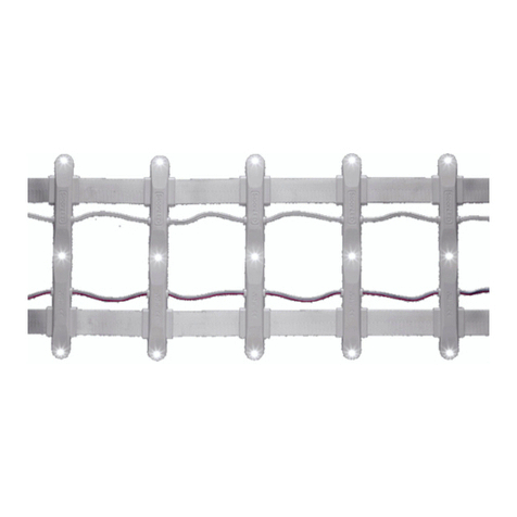
SignBOX II
Installation Guide for 701946-(X)WD201, 701946-(X)WS201
PAGE 1 OF 4
WARNING: Risk of electrical shock. New installation and LED Retrot Kit installation requires knowledge of sign
electrical systems. If not qualied, do not attempt installation. Contact a qualied electrician. Follow all NEC and local
codes. SignBOX II is not suitable for submersion or direct exposure to water for extended periods of time.
AVERTISSEMENT: Risque de choc électrique. La nouvelle installation et l’installation du kit de modication à LED
nécessitent la connaissance des systèmes électriques de signalisation. Si non qualié, ne tentez pas l'installation.
Contactez un électricien qualié. Suivez tous les codes NEC et locaux. SignBOX II ne convient pas à la submersion ni
à l’exposition directe à l’eau pendant de longues périodes.
For New Installation, proceed with Step
1 below. For Retrot Installations, begin
with Retrot Instructions on page 3.
2. Components list:
• SignBOX II assemblies
Double-sided assemblies:
model numbers 701946-(X)WD201
Single-sided assemblies:
model numbers 701946-(X)WS201
•
SloanLED 12 V Class 2 output power supply
(refer to "SloanLED Power Supply Guide for
Sign Products" for appropriate model numbers)
• UL approved 18 AWG (1 mm2) or larger
diameter supply wire
• UL approved wire connectors appropriate
for wire gauge used
•
SignBOX II mounting hardware (as needed):
Clamps (P/N 410155), Couplers (P/N 401330),
and Brackets (P/N 401309)
• #8 (M4) self-drilling/self-tapping tek screws
(required to pierce through strap), minimum
length 5/8" (16 mm)
• Optional: Electrical grade silicone, nylon zip
ties, double-stick mounting tape
ATTENTION: Only install SignBOX II
when ambient temperature is above
5° C (41° F).
1. Tools required: Measuring tape,
wire strippers, gloves, cutting tool (sheet
metal shears/snips, scissors, utility knife),
drill, and screwdriver.
New Installation
4. Cutting product: Cut straps (along dashed
lines) and wires between modules to obtain
required length. Tip: Before cutting wires,
refer to Joining Product section.
3. Measure sign cabinet to determine
quantities of SignBOX II.
Y
X
NOTE: To minimize the potential for shadows
in applications when using frame support tubes,
mount modules or frame support tubes such that
the tubes are centered in between modules and
at a depth that will not directly interfere with the
beam angle of the LEDs.
Use SignComp Adjustable Frame Brace (P/N
5357) or equivalent.
SignBOX II modules
Frame Support
(Tension Bar)
Cabinet Face
SignBOX II
Installation Guide for 701946-(X)WD201, 701946-(X)WS201
PAGE 2 OF 4
4b.Mounting modules with SignBOX II
Clamps (P/N 410155) using SignBOX II
Brackets (P/N 401309): Install brackets
12" (305 mm) center-to-center along returns
of cabinet*. Insert straps from both sides of
module into clamps (track features facing
same direction) making sure clamps are
ush against module, snap closed (avoid
pinching wires), slide onto bracket, and
secure to it with #8 (M4) tek screws. Repeat
on opposite end making sure product is taut.
Opening can t
over existing
sockets
Mounting Product
4a.Mounting modules with SignBOX II
Clamps (P/N 410155) directly to cabinet:
Insert straps from both sides of module into
clamps (track features facing away from
mounting surface) making sure clamps are
ush against module, snap closed (avoid
pinching wires), and secure to cabinet
structure using #8 (M4) tek screws*. Repeat
on opposite end making sure product is taut.
Opened Clamp
4c. Optional mounting in single-sided
cabinet with double stick tape: Using
non-oil based cleaner, clean all mounting
surfaces of sign and bottom of modules
for proper tape adhesion. With double
stick tape on bottom of modules, mount to
back of cabinet. Make sure product is taut.
(Double stick tape is not included.)
Structural Support Guidelines for SignBOX II
Vertical mounting: space supports at even intervals, but no further apart than 8 ft (2.4 m).
Horizontal mounting: space supports at even intervals, but no further apart than 4 ft (1.2 m).
* Refer to Density Guidelines to determine SignBOX II product and installation method.
6.
Use SignBOX II Clamps (P/N 410155) and SignBOX II
Couplers (P/N 401330) to join shorter pieces of
product to required length. Insert straps from both
sides of modules into clamps (track features facing
same direction) making sure clamps are ush against
modules, snap closed (avoid pinching wires), slide
onto couplers, and secure to them with #8 (M4) tek
screws. Connect wires.
Joining Product
5. When cutting wires between modules,
leaving one side longer will aid in joining
product where needed. If, however, wires
are not long enough for connections, use
either jumper wires or remove a module to
maximize wire length.
1.37
3.25
.10 THICK
SignBOX II Coupler dimensions: 3.25" x
1.37" x.10" (82.5 mm x34.8 mm x2.5 mm)
SignBOX II
Installation Guide for 701946-(X)WD201, 701946-(X)WS201
PAGE 3 OF 4
1. Identify sign to be retrot and ensure branch circuit supplying existing sign are within voltage range for LED power supply.
Refer to components list (page 1) and "12 VDC Power Supply Capacity Chart" (page 4).
2. Remove existing lighting equipment intended to be replaced, such as neon or uorescent, and all power supplies, transformers, or ballasts. If previous sign is neon, remove
existing neon and all standoffs to leave an empty sign cabinet. NOTE: All materials removed must be disposed of in accordance with applicable local, state, and federal laws.
3. If required by local, state, or national electrical code, install a new disconnect switch.
4. Determine suitability and structural integrity of existing sign after removal of existing lighting equipment. If retrot does not require the making of any new holes, do not make or
alter any open holes in an enclosure of wiring or electrical components during kit installation. If existing holes are present in a wet or outdoor location sign, repair and seal any
unused openings in the electrical enclosure. Openings greater than 0.5" (12.7 mm) diameter require a metal patch secured by screws or rivets and caulked with non-hardening
caulk. Smaller openings may be sealed with non-hardening caulk.
5. Clean inside of sign using non-oil based cleaner. Follow all manufacturer’s instructions and ensure inside of sign is dry before proceeding with installation. This is an important
step for good adhesion of SignBOX II module mounting tape.
6. To populate sign, refer to SignBOX II density guidelines as well as power supply capacity chart (page 4) to determine appropriate number of modules and power supplies. A list
of acceptable power supply models is shown in the supplemental "SloanLED Power Supply Guide for Sign Products".
7. Follow all instructions on pages 1 and 2 under "New Installation" to properly install LED modules.
8. Connect modules to power supply output as shown on page 3 under "New Installation".
9. Connect power supply input as outlined in power supply installation guide in accordance with local, state and national electrical codes by
qualied personnel. Refer to power supply install guide included with power supply for details.
10. If required, install disconnect switch in accordance with local, state and national electrical codes by qualied personnel.
Retrot Instructions for Existing Signs
WARNING: Risk of re or electric shock. Install this kit only in host signs that have been identied in the installation instructions, and
where the input rating of the retrot kit does not exceed the input rating of the sign. Installation of this LED retrot kit may involve drilling
or punching of holes into the structure of the sign. Check for enclosed wiring and components to avoid damage to wiring and electrical
parts. AVERTISSEMENT: Risque d’incendie ou de choc électrique. Installez ce kit uniquement sur les panneaux hôtes identiés dans
les instructions d'installation et dans lesquels les caractéristiques nominales d'entrée du kit de modication ne dépassent pas celles du
panneau. L’installation de ce kit d’amélioration des LED peut impliquer de percer ou de percer des trous dans la structure de l’enseigne.
Vériez le câblage et les composants inclus pour éviter d'endommager le câblage et les pièces électriques.
GENERAL PURPOSE
RETROFIT SIGN CONVERSION.
FOR USE ONLY IN ACCORDANCE
WITH KIT INSTRUCTIONS.
KIT IS COMPLETE ONLY WHEN ALL PARTS
REQUIRED BY THE INSTRUCTIONS ARE PRESENT.
Connecting Product to Power Supply
20 ft max 10 ft max
option 1
10 ft max
option 2
20 ft max
option 3
Single-sided option Double-sided options
5. Using electrical connectors with appropriate safety agency markings,
daisy chain product as required and connect to power supply as shown
above. CAUTION! Have a licensed electrician connect primary.
ATTENTION! Demandez à un électricien agréé de connecter le
primaire. Modules may be connected in series or parallel. End wires of
SignBOX II should be capped and not tied back to power supply.
WARNING check polarity: All connections must be RED-TO-RED (+) and BLACK-TO-
BLACK (-). Reverse polarity connections may damage the LEDs and will void product
warranty. AVERTISSEMENT vérier la polarité: toutes les connexions doivent être
ROUGE-ROUGE (+) et NOIR-NOIR (-). Des connexions inversées peuvent endommager
les DEL et annuler la garantie du produit.
SloanLED Headquarters
5725 Olivas Park Drive, Ventura, CA, USA
888.747.4LED (888.747.4533) • info@SloanLED.com
SloanLED.com
SloanLED Europe b.v.
Argonstraat 110, 2718 SN Zoetermeer, NL
+31 88 12 44 900 • Europe@SloanLED.com
P/N 401302 Rev K 2022-10-03
Customer service and technical support
SignBOX II
Installation Guide for 701946-(X)WD201, 701946-(X)WS201
PAGE 4 OF 4
US patents and foreign patents pending
Extension of Power Supply Leads
If longer lead wire from power supply to LED modules is needed, an extension can be used. Extension should be kept as short as possible, i.e.,
under 15 ft for 18 AWG UL Listed PLTC (4.6 m for 1 mm² PLTC) or under 50 ft for 14 AWG UL Listed PLTC (15.2 m for 2.5 mm² PLTC).
Troubleshooting:
Entire box/cabinet or product
does not light after complete
installation.
Check connection from power supply lead to rst module. Make sure polarity of connections made at power supply lead and any
jumper wire is correct. Power supply outputs should be connected RED-TO-RED and BLACK-TO-BLACK.
Still does not light.
Check output voltage of power supply using a voltmeter. The output voltage should be DC 12.0 V ± 0.5 V. If there is no output
voltage, have a licensed electrician check input voltage. Make sure power supply is connected correctly and getting primary power.
If power supply is connected properly and getting primary power and there is still no output voltage, try a different power supply.
Still does not light.
If power supply is getting primary power and modules don’t light, there may be a short in the secondary wiring. Check all
connections and cap all loose wires.
The beginning of a strip lights,
but entire strip does not light or
lights intermittently.
The primary cause of a portion of a strip is not lighting or lighting intermittently is a bad connection or reverse polarity connection
between modules that light and modules that don’t light. Check this connection.
One module does not light, but
all others in the product light.
SignBOX
II
is designed so if one module fails, it will not cause the entire box/cabinet or strip to go out. If one module does not
light, but all others in the product do, replace this module with a new one.
12 VDC Power Supply Capacity Chart
Power
output
Maximum modules
single-sided or one leg
of double-sided
Maximum modules
double-sided, both legs
20 W 20 10
25 W
(EU/ROW ONLY) 25 12
30 W
(EU/ROW ONLY) 30 15
60 W 60 30
2 × 60 W 60 × 2 30 × 2
2 × 75 W*
(EU/ROW ONLY) 75 × 2 37 × 2
100 W*
(EU/ROW ONLY) 100 50
Power used per
ft (m) in watts 2.7 W (8.9) 5.4 W (17.7)
E215393
241542
* Must split load at power supply output to prevent exceeding
maximum wire/module ampacity of 5A per single leg.
Capacities based on 90% of power supply output.
NOTE: Refer to "SloanLED Power Supply Guide for Sign Products"
for appropriate 12 V power supply models.
Scan QR code to
download SloanLED
Power Supply Guide
for Sign Products
https://sloanled.com/downloads/SloanLEDPowerSupplyGuideForSignProducts.pdf

This manual suits for next models

4

Other SloanLED Lighting Equipment manuals

SloanLED PrismBEAM24 User manual

SloanLED

SloanLED PrismBEAM24 User manual

SloanLED PosterBOXID 701946-6WLNP1 User manual

SloanLED

SloanLED PosterBOXID 701946-6WLNP1 User manual

SloanLED PosterBOX Slim User manual

SloanLED

SloanLED PosterBOX Slim User manual

SloanLED SignBOX 3 Slim User manual

SloanLED

SloanLED SignBOX 3 Slim User manual

SloanLED 701946-6WMLP1 User manual

SloanLED

SloanLED 701946-6WMLP1 User manual

SloanLED LEDStripe User manual

SloanLED

SloanLED LEDStripe User manual

SloanLED SignBOX II User manual

SloanLED

SloanLED SignBOX II User manual

SloanLED FlexTAPE User manual

SloanLED

SloanLED FlexTAPE User manual

SloanLED PosterBOX User manual

SloanLED

SloanLED PosterBOX User manual

SloanLED HighLINER Instruction Manual

SloanLED

SloanLED HighLINER Instruction Manual

SloanLED Value-Line 701269-WLX-MB User manual

SloanLED

SloanLED Value-Line 701269-WLX-MB User manual

SloanLED LEDStripe User manual

SloanLED

SloanLED LEDStripe User manual

SloanLED BendLUX 701960-6WS241 User manual

SloanLED

SloanLED BendLUX 701960-6WS241 User manual

SloanLED PosterBOX Mini User manual

SloanLED

SloanLED PosterBOX Mini User manual

SloanLED LEDStripe User manual

SloanLED

SloanLED LEDStripe User manual

SloanLED 12 V BP LEDStripe User manual

SloanLED

SloanLED 12 V BP LEDStripe User manual

SloanLED Prism User manual

SloanLED

SloanLED Prism User manual

SloanLED HighLINER 2 User manual

SloanLED

SloanLED HighLINER 2 User manual

SloanLED PosterBOX3 User manual

SloanLED

SloanLED PosterBOX3 User manual

SloanLED PrismBEAM 24V User manual

SloanLED

SloanLED PrismBEAM 24V User manual

SloanLED BendLUX 701960-6WS241 User manual

SloanLED

SloanLED BendLUX 701960-6WS241 User manual

SloanLED SignBOX 3 User manual

SloanLED

SloanLED SignBOX 3 User manual

Popular Lighting Equipment manuals by other brands

Ayra TDC 4 LED user manual

Ayra

Ayra TDC 4 LED user manual

Luminaire led LVP58 installation guide

Luminaire led

Luminaire led LVP58 installation guide

Prilux STAR FLAKE MINI manual

Prilux

Prilux STAR FLAKE MINI manual

Techni-Lux DL-PAR38C75/B user manual

Techni-Lux

Techni-Lux DL-PAR38C75/B user manual

Pinegreen Lighting CL-TP18RGB-EXT user manual

Pinegreen Lighting

Pinegreen Lighting CL-TP18RGB-EXT user manual

Leding Spark Wash 4C user manual

Leding

Leding Spark Wash 4C user manual

Orno OR-SW-7002L4 Operating and instalation instructions

Orno

Orno OR-SW-7002L4 Operating and instalation instructions

Holiday Living Y830-151600090-CY quick start guide

Holiday Living

Holiday Living Y830-151600090-CY quick start guide

LEDone LOD-EXTED Series instructions

LEDone

LEDone LOD-EXTED Series instructions

Osram ADB KLEMANTIS AS 1000 instruction manual

Osram

Osram ADB KLEMANTIS AS 1000 instruction manual

S.R.Smith ROGUE GRAND RAPIDS owner's manual

S.R.Smith

S.R.Smith ROGUE GRAND RAPIDS owner's manual

Verilux HappyLite Mini Plus VT01 user guide

Verilux

Verilux HappyLite Mini Plus VT01 user guide

Toro LT-F3000 installation instructions

Toro

Toro LT-F3000 installation instructions

Matco Tools MFL4500 instruction manual

Matco Tools

Matco Tools MFL4500 instruction manual

Kogan KARILI10LEB user guide

Kogan

Kogan KARILI10LEB user guide

Juniper THIN Suspension installation guide

Juniper

Juniper THIN Suspension installation guide

Commercial Electric EXLEDRG120277 Use and care guide

Commercial Electric

Commercial Electric EXLEDRG120277 Use and care guide

RAB X17 XFU 60W instructions

RAB

RAB X17 XFU 60W instructions

manuals.online logo
manuals.online logoBrands
  • About & Mission
  • Contact us
  • Privacy Policy
  • Terms and Conditions

Copyright 2025 Manuals.Online. All Rights Reserved.