SignBOX 3
Installation Guide for 701946-(X)WDLS1, 701946-(X)WSLS1, and 701946-(X)WSLT1
PAGE 4 OF 5
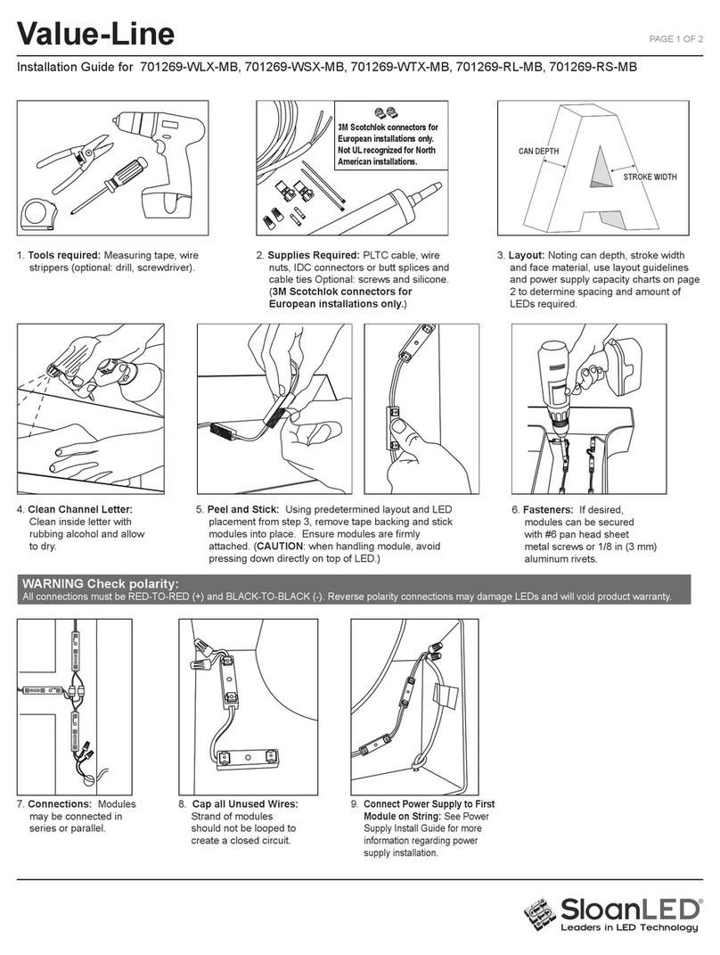
6. Connections: Modules may be connected in series* or parallel.
*For optimal performance, SloanLED recommends connecting no
more than 24 module in series.
7. &DSDOOXQXVHGZLUHV The
strand of modules should not be
looped to create a closed circuit.
8. &RQQHFWSRZHUVXSSO\WR¿UVW
module on string: See power
supply install guide for more
information regarding power
supply installation.
WARNING:
&RQQHFW5HGVWULSHGZLUH
RI/('PRGXOHVWR5HG
ZLUHRISRZHUVXSSO\
Connect White wire of LED
PRGXOHVWR%ODFNZLUHRI
SRZHUVXSSO\5HYHUVH
SRODULW\FRQQHFWLRQVPD\
damage LEDs and will void
SURGXFWZDUUDQW\
5HWUR¿W,QVWUXFWLRQVIRU([LVWLQJ6LJQV
:$51,1*5LVNRI¿UHRUHOHFWULFVKRFN,QVWDOOWKLVNLWRQO\LQKRVWVLJQVWKDWKDYH
EHHQ LGHQWL¿HG LQ WKH LQVWDOODWLRQ LQVWUXFWLRQV DQG ZKHUH WKH LQSXW UDWLQJ RI WKH
UHWUR¿WNLWGRHVQRWH[FHHGWKHLQSXWUDWLQJRIWKHVLJQ,QVWDOODWLRQRIWKLV/('UHWUR¿W
NLWPD\LQYROYHGULOOLQJRUSXQFKLQJRIKROHVLQWRWKHVWUXFWXUHRIWKHVLJQ&KHFNIRU
HQFORVHGZLULQJDQGFRPSRQHQWVWRDYRLGGDPDJHWRZLULQJDQGHOHFWULFDOSDUWV
GENERAL PURPOSE
RETROFIT SIGN CONVERSION.
FOR USE ONLY IN ACCORDANCE
WITH KIT INSTRUCTIONS.
KIT IS COMPLETE ONLY WHEN ALL PARTS
REQUIRED BY THE INSTRUCTIONS ARE PRESENT.
&$87,217XUQR௺SRZHUWRVLJQEHIRUHLQVSHFWLQJRUUHPRYLQJH[LVWLQJOLJKWVRXUFH3RZHUPXVWUHPDLQR௺ZKLOHLQVWDOOLQJ/('SURGXFW
$77(17,21&RXSH]ODOLPHQWDWLRQJpQpUDOHGXSDQQHDXDYDQWGLQWHUYHQLURXGHUHWLUHUODVRXUFHOXPLQHXVHH[LVWDQWH/DOLPHQWDWLRQJpQpUDOH
GRLWrWUHFRXSpHWRXWDXORQJGHOLQVWDOODWLRQGXNLWGHUHPSODFHPHQWHQ/('
1. ,GHQWLI\VLJQWREHUHWUR¿WDQGHQVXUHEUDQFKFLUFXLWVXSSO\LQJH[LVWLQJVLJQDUHZLWKLQYROWDJHUDQJHIRU/('SRZHUVXSSO\
Refer to components list (page 1) and "24 VDC Power Supply Capacity Chart" (page 3).
2. 5HPRYHH[LVWLQJOLJKWLQJHTXLSPHQWLQWHQGHGWREHUHSODFHGVXFKDVQHRQRUÀXRUHVFHQWDQGDOOSRZHUVXSSOLHVWUDQVIRUPHUVRUEDOODVWV
5HPRYHH[LVWLQJQHRQDQGDOOVWDQGRႇVWROHDYHDQHPSW\VLJQFDELQHW127( All materials removed must be disposed of in accordance with
applicable local, state, and federal laws.
3. If required by local, state, or national electrical code, install a new disconnect switch.
4. 'HWHUPLQHVXLWDELOLW\DQGVWUXFWXUDOLQWHJULW\RIH[LVWLQJVLJQDIWHUUHPRYDORIH[LVWLQJOLJKWLQJHTXLSPHQW,IUHWUR¿WGRHVQRWUHTXLUHWKHPDNLQJ
of any new holes, do not make or alter any open holes in an enclosure of wiring or electrical components during kit installation. If existing holes
are present in a wet or outdoor location sign, repair and seal any unused openings in the electrical enclosure.
Openings greater than 0.5" (12.7 mm) diameter require a metal patch secured by screws or rivets and caulked with non-hardening caulk.
Smaller openings may be sealed with non-hardening caulk.
5. Clean inside of sign using non-oil based cleaner. Follow all manufacturer’s instructions and ensure inside of sign is dry before proceeding with
installation. This is an important step for good adhesion of SignBOX 3 module mounting tape.
6. To populate sign, refer to SignBOX 3 density guidelines as well as power supply loading chart (page 1) to determine appropriate number of
modules and power supplies. A list of acceptable power supply models is shown in the "24 VDC Power Supply Capacity Chart" (page 3).
7. Follow all instructions on pages 1 and 2 under "New Installations" to properly install LED modules.
8. Connect modules to power supply output as shown on page 1 under "New Installations"
9. Connect power supply input as outlined in power supply installation guide in accordance with local, state and national electrical codes by
TXDOL¿HGSHUVRQQHO5HIHUWRSRZHUVXSSO\LQVWDOOJXLGHLQFOXGHGZLWKSRZHUVXSSO\IRUGHWDLOV
10. ,IUHTXLUHGLQVWDOOGLVFRQQHFWVZLWFKLQDFFRUGDQFHZLWKORFDOVWDWHDQGQDWLRQDOHOHFWULFDOFRGHVE\TXDOL¿HGSHUVRQQHO


