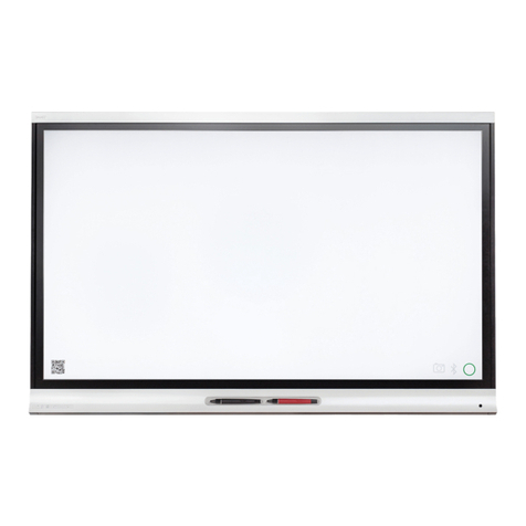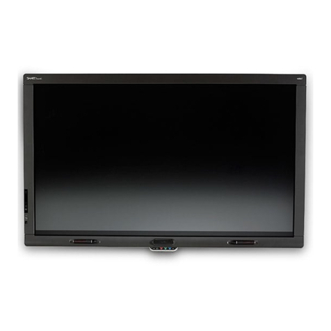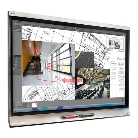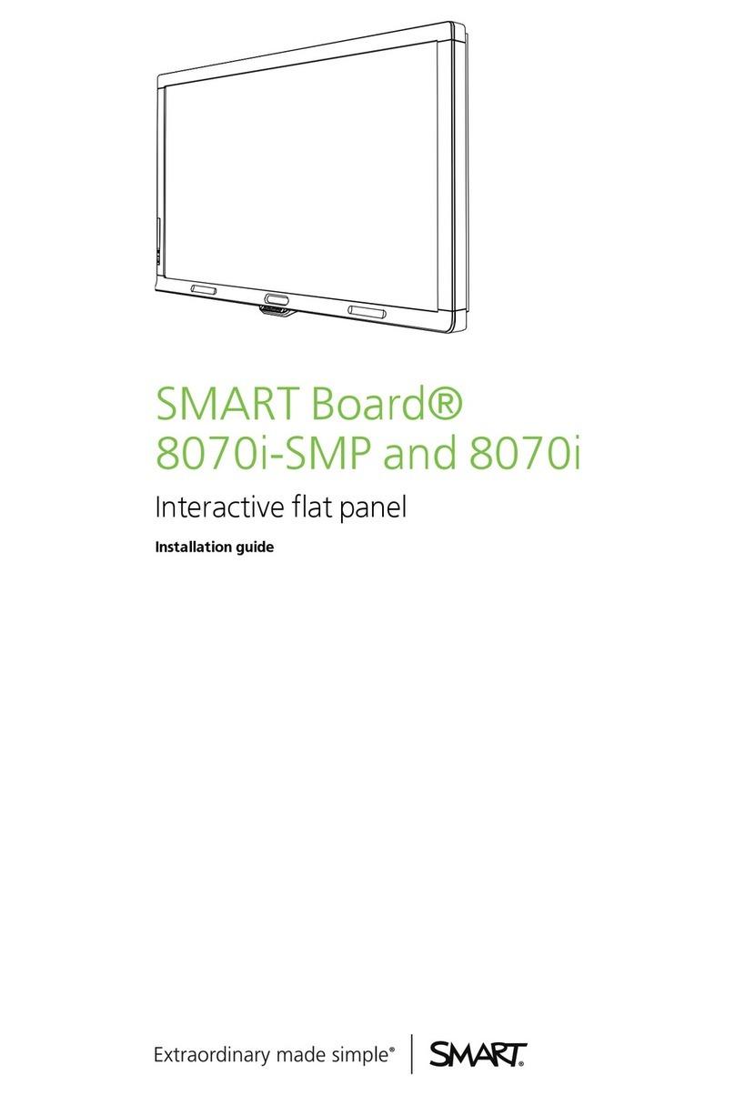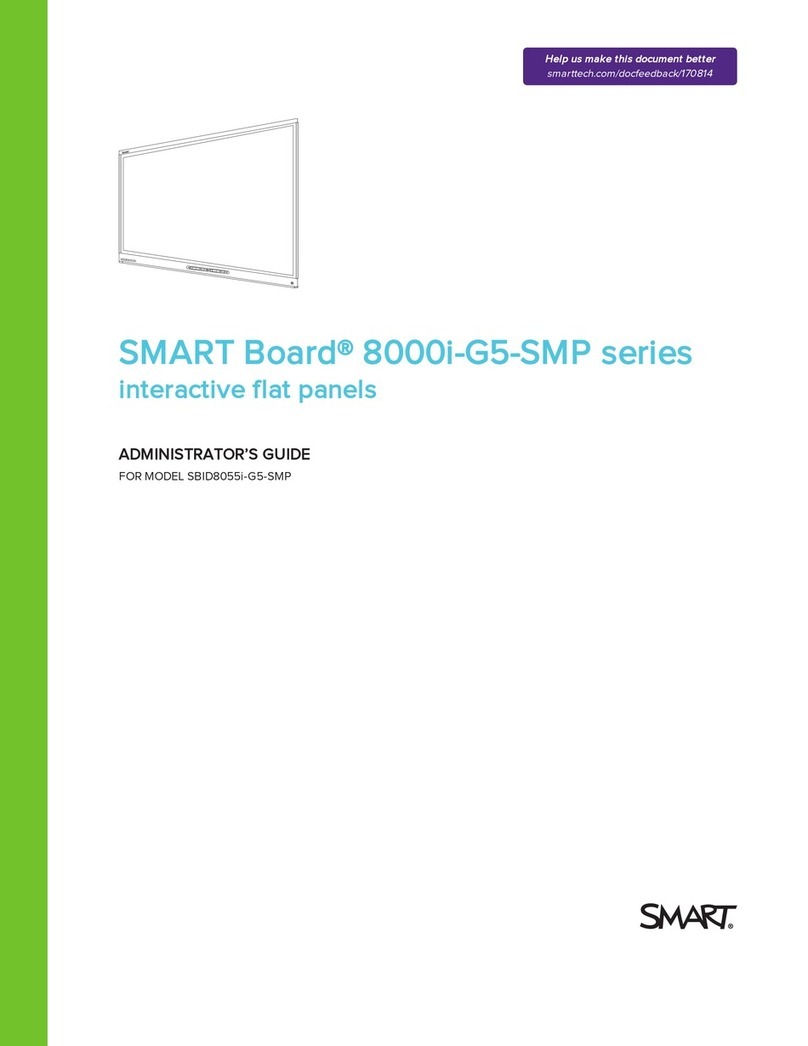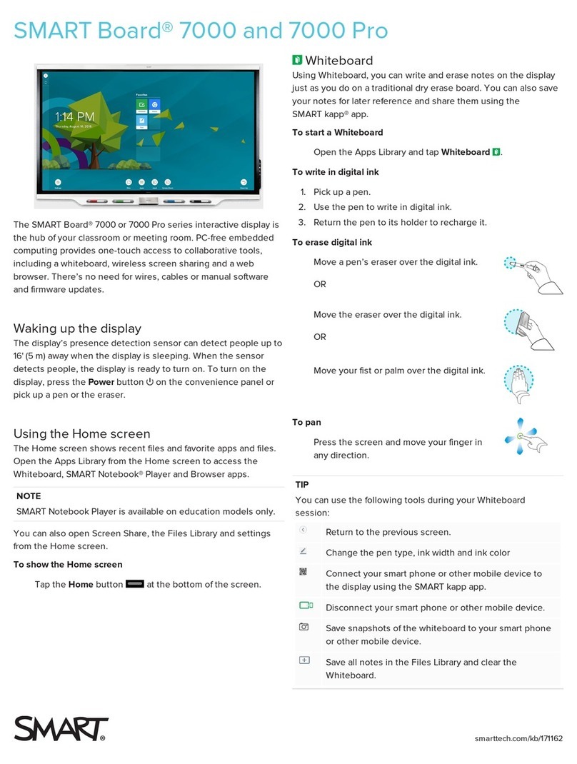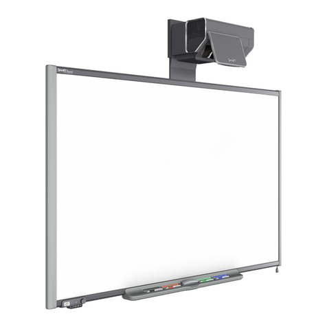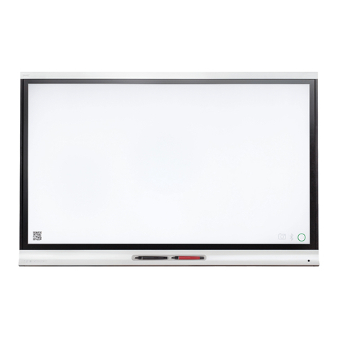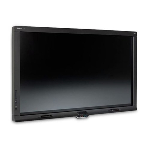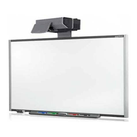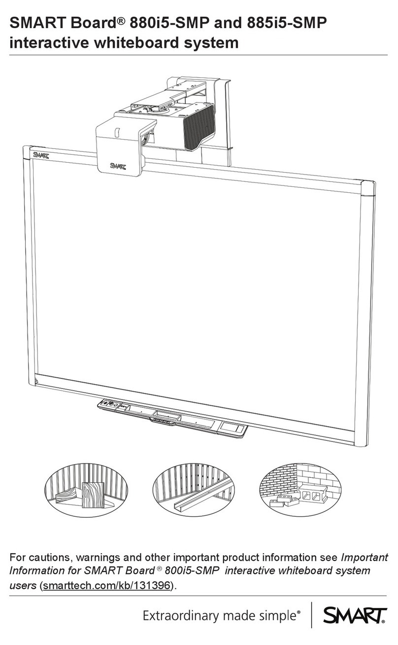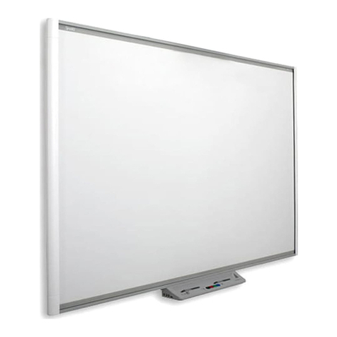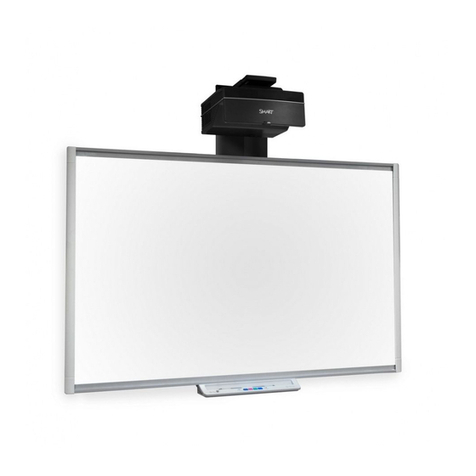
SMART Board™ 8055i
InteractiveDisplay
User'sGuide
DVI
HDMI
1
Extending
USBConnections
SMARTBoard®800 seriesinteractive
whiteboardsand systems
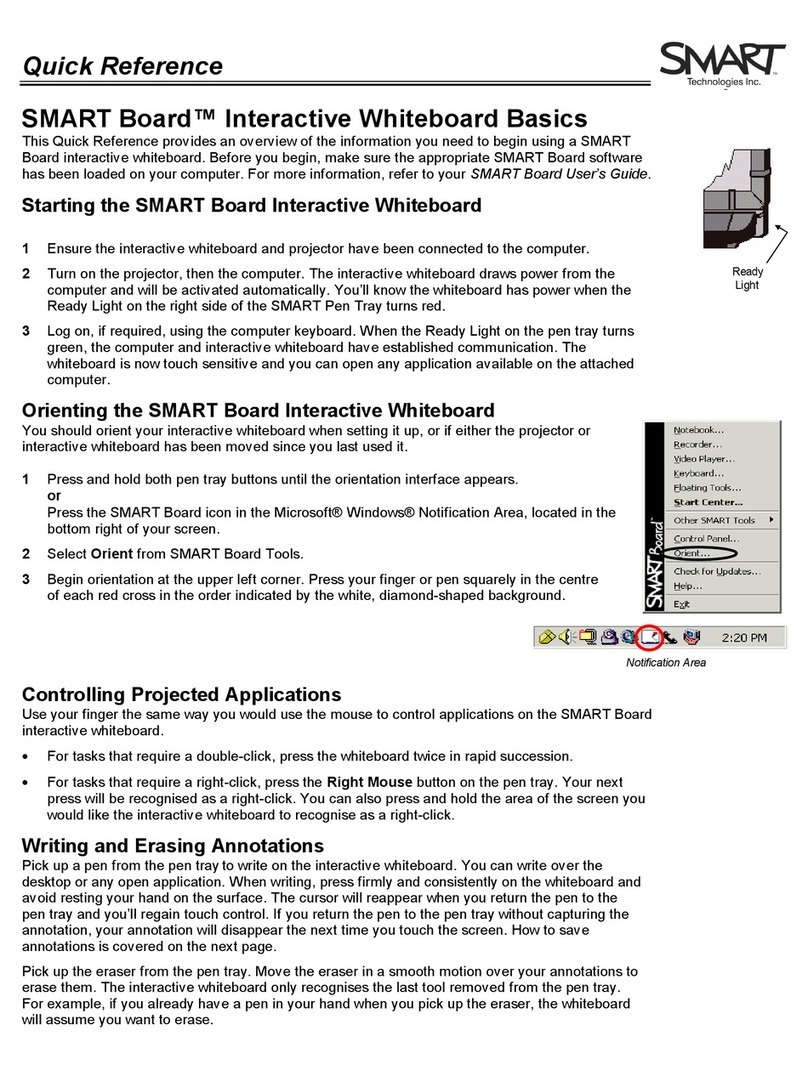
17/04/2012 Conguringyour SMART Board 8055i USB and video port mapping
1/2intranet.smarttech.com/documentation/kb/NatS/Support/170190.htm
C onfiguring the video and touc h input for yo ur
S MA R T B oa rd 8055i interac tive fla t panel
SMAR T hardw ar e SMAR T Board 8 05 5i interactive flat pa nel s
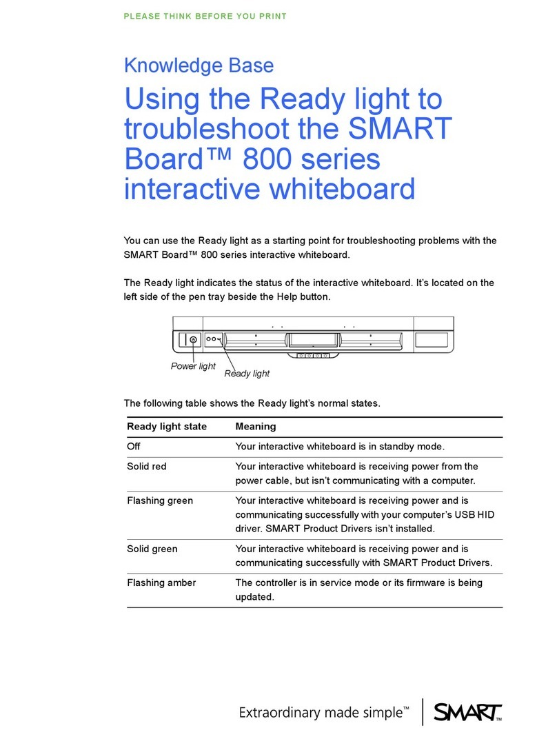
Ove rview
You ca n c onne ct your SMART Boa rd 8 055 i i nterac tive flat pa ne l to u p to thre e computers at once . E a ch computer must be
connected to the intera ctive flatpa nel with a U SB c able for touch inpu tan d a video cab le for video input.
The follo wing ta ble s h ows the defa ult touch inputa nd vide o i nput pa irings .
Compute r Default touch inputc o nne c tion Default video in put connec tion
Comp uter 1 (room computer) USB 1 VGA 1
Comp uter 2 (gues t co mputer) USB 2 VGA 2
Gues t la ptop USB 3 HDMI 2
Ifyou wan tto use a vide oa nd touch inputpa iring other than thed efault, you can chang e thevide oin puts ettings in the on-
scre en displa y me nu.
Detai ls
IM P OR TA N T
Ifyou cha nge the video inputpa ired with a U SB touch input, ens ure the co mputer's video conne ction matche s the ne w video
input. Ifthe video conne ction does no tma tchthe video input, you could los e touch control of yourintera ctive flatpa nel.
Configuring the video and touchi nputpairing
To confi gure the video a nd touch input
1. Pr es s ME NU onthe menu c ontrol panel.
The o n-s cre en menu a ppea rs .
NO T E
You can configure the video a nd touch input with the remote co ntrola s we ll.
2. Bro ws e to SET UP us ing the down button.
3. Pr es s the S E T b utton to s ele ct S E T UP .
4. Bro ws e toUS B SE T TIN G using thedo wn bu tton.
5. Pr es s the right b utton to s ele ct U S B SE TT ING .
6. Pr es s the down buttonto s ele ct a USB rece ptacle .
7. Pr es s the le fta nd rightbuttons tos e lec t a video input for each U S B touch input.
8. Pr es s the MENU button twice toclo s e the on-s cree nm enu.
Firs t publis h ed Apr.1 6, 2012
USB 1 / USB 2 HDMI / DVI / DisplayPort
a
Power switch
Computer 2 (USB 2)
VGA
k
DVI
HDMI
jm
OR OR
r
OR
DisplayPort
DisplayPort
1
2
Inside terminal
panel
Bottom terminal panel
Room
control
n
Remotely managing your
SMART Board™ 8055i
interactive flat panel
Connectingyourinteractive display to an RS-232system 2
Connectiondiagram 2
Serialinterfacesettings3
Powermodes4
RS-232programmingcommandsandresponses 4
Interpretingthe“invalidcmd” response 5
Commandinventory 5
Designatingvideoinput source commands foraspecificv ideoinput6
Designatingatarget interactive display 7
Commandsandcontrols 8
Powerstatecommands8
Videoinputsource 9
Videosourcecommands10
Audiooutputcommands13
Systeminformationcommands14
Serviceinformation 18
Thisdocumentincludesdetailed instructions on how tosetupyour computer or room control system
toremotelymanage your SMART Board™ 8070iinteractivedisplayusingan RS-232 serial interface.
1
52' (16 m) max.
f
h
g
Guest laptop (USB 3)
Guest laptop terminal panel
(For appliance)
q
52' (16 m) max.
p
p
h
HDMI
j
Speakers
b
c
e
f
smarttech.com/kb/170189
smarttech.com/kb/170166
smarttech.com/kb/170190
smarttech.com/kb/170166
smarttech.com/kb/170157
smarttech.com/kb/170177
Alternative cable connections
*1019288*

