MGCP100B-2 Diesel Engine Control Box User Manual Page 9 of 17
4.3 DESCRIPTION OF CONTROL BOX INDICATORS AND MODULES
1) Lead Power Indicator: illuminates when lead power is available.
2) Standby Power Indicator: illuminates when standby power is available.
3) Buzzer: when controller detects fault signals, buzzer makes a beeping sound and flashes. Press
“Alarm Mute”key can remove the sound.
4) AC Power Indicator: illuminates when AC power is available.
5) Charging Indicator: illuminates when the battery is charged by the charger.
6) Water Heater Indicator: illuminates when water heater is working.
7) Power Switch: control DC power supply. Turn right to power on, and display screen illuminates,
then modules start to self-check. Sound-light alarms will be initiated if alarm signals occur or
parameters reach to alarm limit value, otherwise, the screen displays normal parameters and
status.
8) Local/Remote Control Knob: used for switching local mode and remote control mode. In local
mode, control box can start/stop engine, and transfer between idle and rated speed; in remote
control mode, control box can start/stop engine through remote control module or remote
start/stop signals.
9) Idle/Rated Speed Knob: used for switching engine in idle speed or rated speed.
10) Water Heating On-off Knob: it is in “off” position under normal condition. When the water heater is
required to work, it is in “on” position and water heater indicator illuminates.
11) Speed Raise/Drop Knob: it is a three-position automatic reset switch. It is in middle position under
normal condition. When it turns left, speed drop command is active, the speed is adjusted to lower
limit; when it turns right, speed raise command is active, the speed is adjusted to upper limit.
12) Emergency Stop Key: press this key when emergency occurs, emergency stop outputs and engine
will stop immediately.
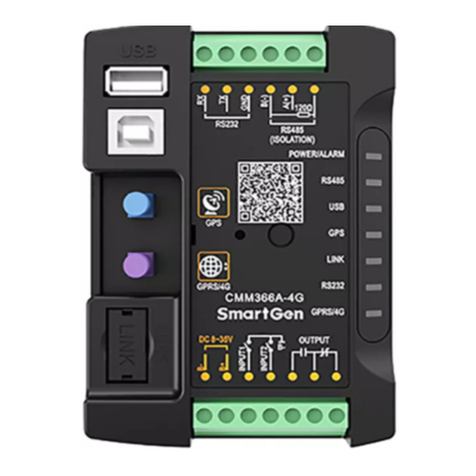
13) AIN8 analog input module is 8-way analog input module, each sensor input on the module can be
configured as PT100 resistance input, (4-20)mA current input and (0-5)V voltage input. The
measured data is transmitted to the main controller via CANBUS, and main controller’s alarm
threshold corresponding to each sensor of AIN8 module can be configured. When the alarm
condition is reached, corresponding sensor alarm information will be displayed on the main
controller. It should be noted that this module must be used with main controller.
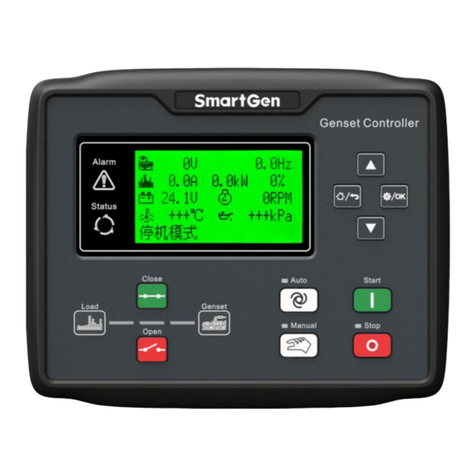
14) HMP300 power integrated protection module integrates digitization, intelligentization and network
technology, can measure genset voltage, current, power, frequency data and output corresponding
actions when abnormal situations occur. All parameters can be adjusted from front panel or LINK
port via PC. CANBUS port enables it to connect HMC9000/HMC6000 module to simultaneously
measure and display power and engine data. It is suitable for 3P4W, SP3W, 1P2W, 2P3W power
with 50Hz/60Hz system.
15) RPU560A redundant protection unit can autonomously maintain the engine running and protect it.
The module is connected to HMC9000/HMC6000 via CANBUS port. All data and alarm information
can be checked on the master module. It has two working modes, one is applied to synchronously
protect engine normal running with master module, another is applied to automatically maintain
and protect engine normal running after master module is inactive. It has 4-way programmable
digital fault shutdown input, 5-way relay output, emergency stop and override mode input port that
is suitable for marine main propulsion, main genset, emergency units or pump units.
NOTE:
1) Emergency stop key can’t be used in non-emergency situation.


