manuals.online logo
Brands
  1. Home
  2. •
  3. Brands
  4. •
  5. Solplanet
  6. •
  7. Inverter
  8. •
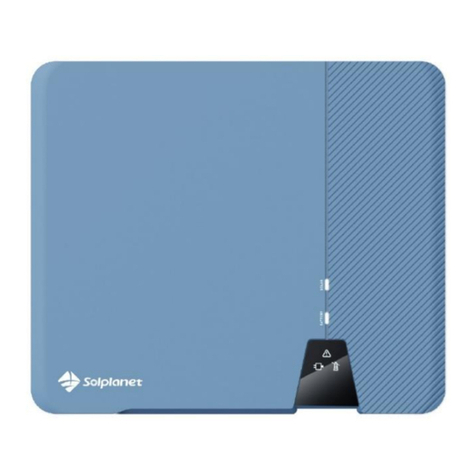
  9. Solplanet ASW30K-LT-G2 User manual

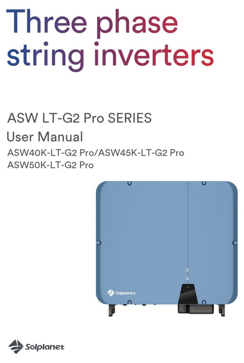
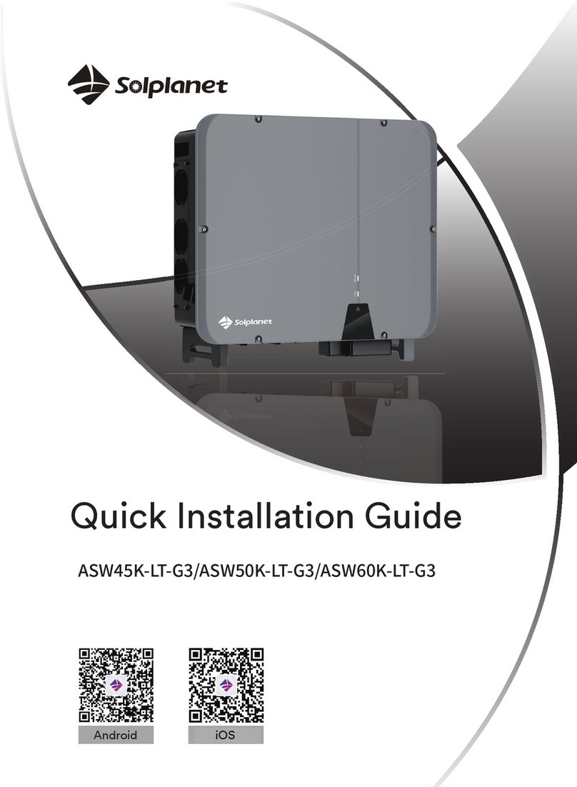
Solplanet ASW30K-LT-G2 User manual

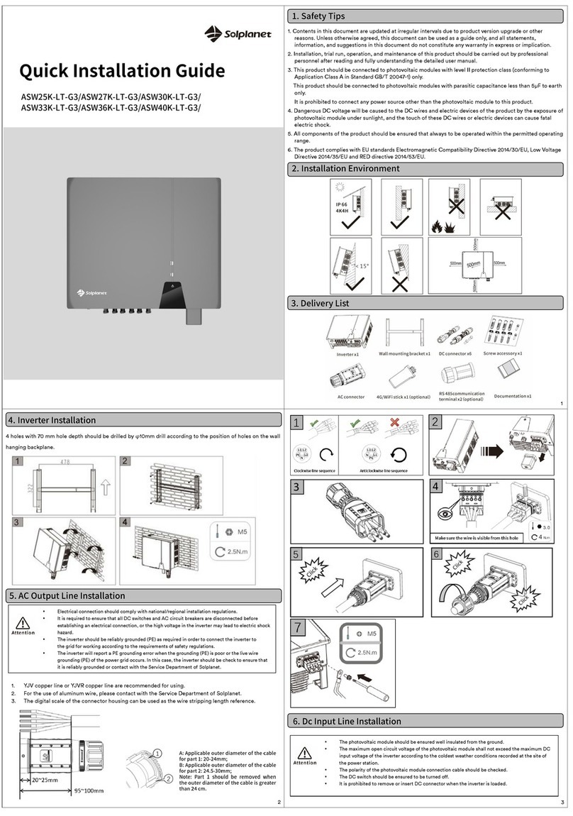
Quick Installation Guide
ASW30K-LT-G2/ ASW33K-LT-G2
ASW36K-LT-G2/ ASW40K-LT-G2
ASW45K-LT-G2/ ASW50K-LT-G2
1. The contents of this document will be updated irregularly for product version upgrade or other
reasons. Unless otherwise specified, this document only works as guide. All statements,
information and suggestions in this document do not constitute any guarantee.
2. This product can only be installed, commissioned, operated and maintained by technicians who
have carefully read and fully understood the user manual.
3. This product must only be connected with PV modules of protection class II (in accordance with
IEC 61730, application class A). PV modules with a high capacitance to ground must only be used
if their capacity does not exceed 1μF.Do not connect any sources of energy other than PV
modules to the product.
4. When exposed to sunlight, the PV modules generate dangerous high DC voltage which is present
in the DC cable conductors and live components. Touching live DC cable conductors and live
components can result in lethal injuries due to electric shock.
5. All components must remain within their permitted operating ranges at all times.
6. The product complies with Electromagnetic compatibility 2014/30/EU, Low Voltage Directive
2014/35/EU and Radio Equipment Directive 2014/53/EU.
1. Ensure that the inverter is installed out of the reach of children.
2. To ensure best operating status and prolonged service life, the
ambient temperature of the location should be ≤40°C.
3. To avoid direct sunlight, rain, snow, pooling of water on the inverter, it is
suggested to mount the inverter in places which are shaded during the majority of
the day or to install an external cover that provides shade for the inverter.
Do not place a cover directly on top of the inverter.
4. The mounting condition must be suitable for the weight and size of the inverter. The inverter is suitable
to be mounted on a solid wall that is vertical or tilted backwards (Max. 15°). It is not recommended to
install the inverter on walls made of plasterboards or similar materials. The inverter may emit noise
during operation.
5. To ensure adequate heat dissipation, the recommended clearances between the
inverter and other objects is shown in the image to the right:
1. Use a Φ12mm bit to drill 3 holes at a depth of about 70mm according to the location of the wall
mounting bracket. (Figure A)
2. Insert three wall plugs into the wall and fix the wall mounting bracket to the wall by inserting three
M8 Screws (SW13). (Figure B)
3. Hang the inverter to the wall mounting bracket. (Figure C)
4. Secure the inverter to the wall mounting bracket on both sides using two M4 screws.
Screwdrivertype:PH2, torque:1.6Nm. (Figure D)
1. AC cable requirements are as follows. Strip the cable as shown in the figure, and crimp the copper
wire to the appropriate OT terminal (provided by the customer).
Object
Description
Value
A
External diameter
20-42mm
B
Copper conductor cross-section
16-50mm2
C
Stripping length of the insulated conductors
Matching terminal
D
Stripping length of the cable outer sheath
130mm
The external diameter of the OT terminal shall be less than 22mm.
The PE conductor must be 5 mm longer than the L and N conductors.
Please use a copper - aluminum terminal when aluminum cable is selected.
2. Remove the plastic AC/COM cover from the inverter, pass the cable through the waterproof
connector on the AC/COM cover in the wall-mounting accessories package, and retain the
appropriate sealing ring according to the wire diameter, lock the cable terminals onto the inverter-
side wiring terminals respectively (L1/L2/L3/N/PE,M8/M5), install the AC insulation sheets onto the
wiring terminals (as shown in Step 4 of the figure below), then lock the AC/COM cover with screws
(M4x10), and finally tighten the waterproof connector. (Torque M4:1.6Nm; M5:5Nm; M8:12Nm;
M63:SW65,10Nm)
3. If required, you can connect a second protective conductor as equipotential bonding.
1. Please refer to “DC Connector Installation Guide”.
2. Before DC connection, insert the DC plug connectors with
sealing plugs into DC input connectors of the inverter to
ensure protection degree.
Object
Description
M5×12 screw
Screwdriver type: PH2, torque: 2.5Nm
OT terminal lug
Customer provided, type: M5
Grounding cable
Copper conductor cross-section: 16-25mm2
3
1
2
Figure A
Figure B
I. Safety Instruction
II. Mounting environment
III. Scope of delivery
IV. Inverter’s mounting
Figure C
Figure D
V.AC connection
▪All electrical installations must be done in accordance with all local and national rules.
▪Make sure that all DC switches and AC circuit breakers have been disconnected before establishing
electrical connection. Otherwise, the high voltage within the inverter may lead to electrical shock.
▪In accordance with safety regulations, the inverter need be grounded firmly. When poor ground
connection (PE) occurs, the inverter will report PE grounding error. Please check and ensure that
the inverter is grounded firmly or contact AISWEI service.
VI.DC connection
▪Make sure PV modules have good insulation against ground.
▪On the coldest day based on statistical records, the Max. open-circuit voltage of the PV modules
must not exceed the Max. input voltage of the inverter.
▪Check the polarity of DC cables.
▪Ensure that DC switch has been disconnected.
▪Do not disconnect DC connectors under load.
VII. Communication setup
▪Separate communication cables from power cables and serious interference sources.
▪The communication cables must be CAT-5E or higher-level shield cables. Pin assignment complies
with EIA/TIA 568B standard. For outdoor use, the communication cables must be UV-resistant. The
total length of communication cable cannot exceed 1000m.
▪If only one communication cable is connected, insert a sealing plug into the unused hole of sealing
ring of the cable gland.
▪Before connecting communication cables, ensure the protective film or communication plate attached to the
communication opening on the inverter is sealed tightly.
1. COM1: WiFi / 4G (optional)
2. COM2: RS485 (Type 1)
1) RS485 cable pin assignment as below.
2) Disassemble the AC/COMcover and unscrew the waterproof connector, and thenguide the cable through
the connector and insert it into the corresponding terminal. Assemble the AC/COM cover with M4 screws
and screw the waterproof connector. (Screw torque: M4:1.6Nm; M25:SW33,7.5 Nm)
3. COM2: RS485 (Type 2)
1) The cable pin assignment as below, others refer to the above type 1.
4. COM2: RS485 (Multi-machine communication)
1) Refer to the following Settings
1. Switch on AC circuit breaker between the inverter and the grid.
2. Switch on DC switch.
3. Please refer to the AiProfessional/Aiswei App manual for commissioning of the inverter via Wifi.
4. When there is sufficient DC power and the grid conditions are met, the inverter will start to
operate automatically.
Within the scope of the EU directives:
- Electromagnetic compatibility 2014/30/EU
(L 96/79-106 ,March 29, 2014)(EMC)
- Low voltage directive 2014/35/EU (L 96/357-374 ,March 29, 2014)(LVD)
- Radio equipment directive 2014/53/EU (L 153/62-106 ,May 22, 2014)(RED)
AISWEI Technology (Shanghai) Co., Ltd. confirms herewith that the inverters mentioned in this document
are in compliance with the fundamental requirements and other relevant provisions of the above
mentioned directives.
The entire EU Declaration of Conformity can be found at www.aiswei-tech.com.
If you have any technical problems with our products, please contact our service.
Provide the following information to assist in providing you with the necessary assistance:
- Inverter device type
- Inverter serial number
- Type and number of connected PV modules
- Error code
- Mounting location
- Warranty card
EMEA
Service email: ser[email protected]t
APAC
Service email: service.APAC@solplanet.net
LATAM
Service email: service.LATAM@solplanet.net
Aiswei Greater China
Service email: service.china@aiswei-tech.com
Hotline: +86 400 801 9996
Taiwan
Service email: service.taiwan@aiswei-tech.com
Hotline: +886 809089212
https://solplanet.net/contact-us/
5
6
▪Only applicable to the company's products, can’t be connected to other USB devices.
▪The connection refers to “GPRS/ WiFi-stick User Manual”.
VIII. Commissioning
▪Check that the inverter is grounded reliably.
▪Check that the ventilation condition surrounding the inverter is good.
▪Check that the grid voltage at the point of connection of the inverter is within the permitted range.
▪Check that the sealing plugs in DC connectors and the communication cable gland are sealed tightly.
▪Check that grid connection regulations and other parameter settings meet safety requirements.
IX. EU Declaration of Conformity
XI. Contact
4

Other manuals for ASW30K-LT-G2

1

This manual suits for next models

5

Other Solplanet Inverter manuals

Solplanet ASW6000-S User manual

Solplanet

Solplanet ASW6000-S User manual

Solplanet ASW LT Series User manual

Solplanet

Solplanet ASW LT Series User manual

Solplanet ASW LT Series User manual

Solplanet

Solplanet ASW LT Series User manual

Solplanet ASW3K-LT-2 Pro User manual

Solplanet

Solplanet ASW3K-LT-2 Pro User manual

Solplanet ASW 3-6K S G2 Series User manual

Solplanet

Solplanet ASW 3-6K S G2 Series User manual

Solplanet ASW3000-T User manual

Solplanet

Solplanet ASW3000-T User manual

Solplanet ASW08KH-T1 User manual

Solplanet

Solplanet ASW08KH-T1 User manual

Solplanet ASW75K-LT User manual

Solplanet

Solplanet ASW75K-LT User manual

Solplanet ASW S-A Series User manual

Solplanet

Solplanet ASW S-A Series User manual

Solplanet ASW25K-LT-G3 User manual

Solplanet

Solplanet ASW25K-LT-G3 User manual

Solplanet ASW75K-LT User manual

Solplanet

Solplanet ASW75K-LT User manual

Solplanet ASW LT Series User manual

Solplanet

Solplanet ASW LT Series User manual

Solplanet ASW05kH-T2 User manual

Solplanet

Solplanet ASW05kH-T2 User manual

Solplanet ASW H-T1 Series User manual

Solplanet

Solplanet ASW H-T1 Series User manual

Solplanet ASW30K-LT-G2 User manual

Solplanet

Solplanet ASW30K-LT-G2 User manual

Solplanet ASW T Series User manual

Solplanet

Solplanet ASW T Series User manual

Solplanet ASW LT-G2 Pro Series User manual

Solplanet

Solplanet ASW LT-G2 Pro Series User manual

Solplanet ASW45K-LT-G3 User manual

Solplanet

Solplanet ASW45K-LT-G3 User manual

Solplanet ASW45K-LT-G3 User manual

Solplanet

Solplanet ASW45K-LT-G3 User manual

Solplanet ASW H-S Series User manual

Solplanet

Solplanet ASW H-S Series User manual

Solplanet ASW LT-G2-A Series User manual

Solplanet

Solplanet ASW LT-G2-A Series User manual

Solplanet ASW8K-LT-G2 User manual

Solplanet

Solplanet ASW8K-LT-G2 User manual

Solplanet ASW S-GW Series User manual

Solplanet

Solplanet ASW S-GW Series User manual

Solplanet ASW H-S2 Series User manual

Solplanet

Solplanet ASW H-S2 Series User manual

Popular Inverter manuals by other brands

Victron energy 48/3000/35-32 manual

Victron energy

Victron energy 48/3000/35-32 manual

Unipower SLI 15 Installation & operating manual

Unipower

Unipower SLI 15 Installation & operating manual

Engel SHX8000Di owner's manual

Engel

Engel SHX8000Di owner's manual

CE+T Power TSI Bravo user manual

CE+T Power

CE+T Power TSI Bravo user manual

SimpliPhi Outback AccESS installation manual

SimpliPhi

SimpliPhi Outback AccESS installation manual

AEG AGN6500 Original instructions

AEG

AEG AGN6500 Original instructions

Platinum 13000 TL Installation and user guide

Platinum

Platinum 13000 TL Installation and user guide

Siel SOLEIL SRT user manual

Siel

Siel SOLEIL SRT user manual

Hoval TopTronic E Solar TTE-SOL instructions

Hoval

Hoval TopTronic E Solar TTE-SOL instructions

Goodwe ABD Series Quick installation guide

Goodwe

Goodwe ABD Series Quick installation guide

Enerdrive ePRO owner's manual

Enerdrive

Enerdrive ePRO owner's manual

Central Machinery 95105 Set up and operating instructions

Central Machinery

Central Machinery 95105 Set up and operating instructions

York YH9FXH24BAH--FX Service manual

York

York YH9FXH24BAH--FX Service manual

Generac Power Systems 13694330200 owner's manual

Generac Power Systems

Generac Power Systems 13694330200 owner's manual

Huawei SUN2000-(3KTL-12KTL)-M0 quick guide

Huawei

Huawei SUN2000-(3KTL-12KTL)-M0 quick guide

Kostal PIKO MP plus 1.5-1 technical information

Kostal

Kostal PIKO MP plus 1.5-1 technical information

BELTTT BEP150S manual

BELTTT

BELTTT BEP150S manual

Goodwe ES Series user manual

Goodwe

Goodwe ES Series user manual

manuals.online logo
manuals.online logoBrands
  • About & Mission
  • Contact us
  • Privacy Policy
  • Terms and Conditions

Copyright 2025 Manuals.Online. All Rights Reserved.