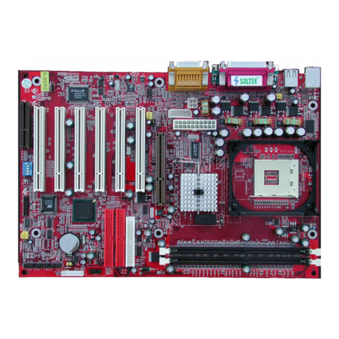
SOLTEK SL-67EV1 Use and care manual

This User’s Guide & Technical Reference is for assisting system
manufacturers and end-users in setting up and installing the
mainboard.
Every effort has been made to ensure that the information in this
manual is accurate. Solte Computer Inc. is not responsible for
printing or clerical errors. Information in this document is subject to
change without notice and does not represent a commitment on
the part of Solte Computer Inc.
No part of this manual may be reproduced, transmitted, translated
into any language in any form or by any means, electronic or
mechanical, including photocopying and recording, for any purpose
without the express written permission of Solte Computer Inc.
Companies and products mentioned in this manual are for identifi-
cation purpose only. Product names appearing in this manual may
or may not be registered trademar s or copyrights of their respec-
tive companies.
Solte Computer Inc. Provides this manual “AS IS” without war-
ranty of any ind, either express or implied, including but not limited
to the implied warranties or conditions of merchantability or fitness
for a particular purpose. In no event shall Solte Computer Inc. Be
liable for any loss or profits, loss of business, loss of use or data,
interruption of business, or for indirect, special, incidental, or con-
sequential damages of any ind, even if Solte Computer Inc. Has
been advised of the possibility of such damages arising from any
defect or error in this manual or product.
© Copyright 2000 Soltek Computer Inc.
All rights reserved
Model : SL- 7EV1
Edition : April, 2000
Version : 2.0
http://www.solte .com.tw
e-mail: support@solte .com.tw
NOTICE TO END USER

7EV1
2
C O N T E N T
Chapter 1: Introduction .......................... 4
1-1 CPU .................................................................................... 4
1-2 CHIPSET ............................................................................ 4
1-3 L2 CACHE .......................................................................... 4
1-4 MAIN MEMORY .................................................................. 4
1-5 BIOS ................................................................................... 4
1- SUPER I/O FUNCTON ....................................................... 4
1-7 OTHER FEATURES ........................................................... 5
1-8 MOTHERBOARD LAYOUT ................................................
Chapter 2: Hardware Setup .................... 7
2-1 CPU TYPE CONFIGURATION ........................................... 7
2-2 SYSTEM MEMORY CONFIGURATION ............................. 8
2-3 JUMPER SETTINGS .......................................................... 8
2-4 CONNECTORS ................................................................ 11
2-4.1 J2 SWITCH SIGNAL SUMMARY .................................. 12
2-4.2 J3 SWITCH SIGNAL SUMMARY .................................. 13
Chapter 3: BIOS Setup.......................... 14
3-1 STANDARD CMOS SETUP ............................................. 15
3-2 BIOS FEATURES SETUP ................................................ 17
3-3 CHIPSET FEATURES SETUP ......................................... 21
3-4 POWER MANAGEMENT SETUP .................................... 24
3-5 PNP / PCI CONFIGURATION SETUP.............................. 28
3- LOAD SETUP DEFAULTS ............................................... 30
3-7 CPU SPEED SETTING..................................................... 31
3-8 INTEGRATED PERIPHERALS ........................................ 33
3-9 SUPERVISOR / USER PASSWORD ............................... 37

7EV1
3
3-10 HDD AUTO DETECTION ............................................... 38
3-11 SAVE & EXIT SETUP ..................................................... 38
3-12 EXIT WITHOUT SAVING................................................ 38

7EV1
4
Chapter 1: Introduction
1-1 CPU
• Supports Intel Celeron / Pentium II / Pentium !!! CPUs using SLOT-1 at
233MHz up to 1GHz or higher.
• Supports CPU voltage auto-detect circuit.
• Supports 66 / 100 / 103 / 112MHz Bus Cloc with auto-detect. (BIOS provides
75 / 83 / 103 / 112 / 133 / 150MHz Bus Cloc without auto-detect)
1-2 CHIPSET
• VIA VT82C693A + VT82C596B chipset with 133MHz FSB.
• PCI Rev 2.1, 5V, 33MHz interface compliant.
• Supports 66 / 100 / 133MHz, 3.3V AGP (Accelerated Graphics Port) slot.
1-3 L2 CACHE
• Pentium II / Pentium !!! supports 512K write bac cache with Pipelined
Burst SRAMs.
1-4 MAIN MEMORY
• Memory range from 8MB up to 768MB (SDRAM) with DRAM Table Free
configuration.
• Supports SDRAM with 12 / 10 / 8 / 6 ns speed.
• Supports 3pcs 168pin DIMM soc ets. (3.3V Unbuffered and 4 cloc type)
• DRAM supports ECC or Parity function.
1-5 BIOS
• Award Plug and Play BIOS.
• Supports ACPI and legacy APM.
• Flash Memory for easy upgrade.
1- SUPER I/O FUNCTON
• Integrated USB (Universal Serial Bus) controller with 2 USB ports.
• Supports 2 IDE channels with 4 IDE devices. (including ZIP / LS-120 devices)
• Provides PCI IDE Bus Master function and supports Ultra DMA33 / 66
function.
• Provides 1 floppy port.
• 2 high speed 16550A FIFO UART ports.

7EV1
5
• 1 parallel port with EPP / ECP / SPP capabilities.
• PS/2 mouse connector.
• Built-In RTC, CMOS, eyboard controller on single I/O chip.
• Peripherals boot function. (with ATX power)
1-7 OTHER FEATURES
• ATX size 17.0cm x 30.5cm.
• 5 PCI Master slots, 2 ISA slots and 1 AGP slot.
• Provides DIP switch setting.
• Supports 66 / 100 / 133MHz Bus Cloc .
• Supports eyboard power on function.
• Supports WOL (Wa e On LAN) function.
• BIOS supports 103 / 112 / 133 / 150MHz Bus Cloc .

7EV1
1-8 MOTHERBOARD LAYOUT
• DEFAULT SETTING: Celeron 300/66MHz, Pentium II / Pentium !!! 450/
100MHz.
NOTE: FOR 100 / 133MHz CPU ENVIRONMENT, THE SDRAM MUST COMPLY WITH PC-100 / PC-
133 SPEC.
1 3
JP3
JP4
3 1
3 1
JP2
3
1
JBAT1
3
1
JP
1
3
JP7
JVGA1
PFAN1
JWOL1
SFAN1
CFAN1
PCI 1
PCI 2
PCI 3
PCI 4
PCI 5
HDD/LED
SPK RESET KEYLOCK SUSLED
IR PWR/SW
IDE 2
IDE 1
FDD
DIMM 1
DIMM 2
DIMM 3
15
15
USB0
USB1 PS/2
MOUSE
PS/2
K/B
LPT1
COM2 COM1
AGP
Li
Battery
SLOT 1
ATX POWER
ISA 1
ISA 2
FLASH BIOS
SW1
ON DIP
1 2 3 4 5
VIA
93A
VIA
59 B
J2
J3

7EV1
7
Chapter 2: Hardware Setup
2-1 CPU TYPE CONFIGURATION
Celeron 2 / ( MHz * 4.0x)
Pentium II 400/100 (100MHz * 4.0x)
Pentium III 533B/133 (133MHz * 4.0x)
Pentium III 533EB/133 (133MHz * 4.0x)
OFF
OFF
ON
ON
ON
ON
ON
1 2 3 4 5 6
Celeron 300/ ( MHz * 4.5x)
Pentium II/III 450/100 (100MHz * 4.5x)
Pentium III 00B/133 (133MHz * 4.5x)
Pentium III 00EB/133 (133MHz * 4.5x)
OFF
OFF
OFF
ON
ON
ON
ON
1 2 3 4 5 6
Celeron 333/ ( MHz * 5.0x)
Pentium II/III 500/100 (100MHz * 5.0x)
Pentium III 500E/100 (100MHz * 5.0x)
Pentium III 7/133 (133MHz * 5.0x)
OFF
OFF
OFF
ON
ON
ON
ON
1 2 3 4 5 6
Celeron 3 / ( MHz * 5.5x)
Pentium II/III 550/100 (100MHz * 5.5x)
Pentium III 550E/100 (100MHz * 5.5x)
Pentium III 733/133 (133MHz * 5.5x)
OFF
OFF
OFF
OFF
ON
ON
ON
1 2 3 4 5 6
Celeron 400/ ( MHz * .0x)
Pentium II/III 00/100 (100MHz * .0x)
Pentium III 00E/100 (100MHz * .0x)
Pentium III 800EB/133 (133MHz * .0x)
OFF
OFF
ON
ON
ON
ON
ON
1 2 3 4 5 6
Celeron 433/ ( MHz * .5x)
Pentium II 50/100 (100MHz * .5x)
Pentium III 50/100 (100MHz * .5x)
OFF
OFF
OFF
ON
ON
ON
ON
1 2 3 4 5 6
Celeron 4 / ( MHz * 7.0x)
Pentium III 700/100 (100MHz * 7.0x)
OFF
OFF
OFF
ON
ON
ON
ON
1 2 3 4 5 6
Celeron 500/ ( MHz * 7.5x)
Pentium III 750/100 (100MHz * 7.5x)
Pentium III 1000B/133 (133MHz * 7.5x)
OFF
OFF
OFF
OFF
ON
ON
ON
1 2 3 4 5 6
Celeron 533/ ( MHz * 8.0x)
Pentium III 800/100 (100MHz * 8.0x)
OFF
OFF
OFF
ON
ON
ON
ON
1 2 3 4 5 6
Using these CPUs which bus ratio exceed
8.0x, user can not change all values from
the DIP switch but detection by BIOS
automatically.
Over 8.0x
Manual DIP switches for diverse CPUs

7EV1
8
2-2 SYSTEM MEMORY CONFIGURATION
• This VIA 693 Apollo Pro Plus motherboard supports 168pin DIMM of 4MB,
8MB, 16MB, 32MB, 64MB and 128MB to form a memory size between
8MB up to 768MB (SDRAM). VIA 693 Apollo Pro Plus chipset provides
“Table-Free” function. It means that users can install DRAM with any
configuration and in any ban , and that is why the DRAM table is not needed
but do remember that the DRAM must be 3.3V type. For 100 / 133MHz
CPU environment, the SDRAM specification must comply with PC-
100 / PC-133 spec.
2-3 JUMPER SETTINGS
CPU FAN
CFAN1/SFAN1/PFAN1: ONBOARD FAN (12V)
SFAN1
CFAN1
SYSTEM FAN
PFAN1
CHASSIS FAN
NOTE : • If he JP2 is fixed by jumperwire, hen he mo herboard doesn’ sup-
por keyboard power on func ion.
• When he keyboard power on func ion shows any compa ible problem,
choose Disabled and repor o he keyboard vendor/manufac urer.
• Keyboard power on func ion mus be se from he BIOS. Refer o he
“In egra ed and Peripherals” sec ion in he Chap er 3.
Disabled (default)
JP2: KEYBOARD POWER ON
1 3
JP2
Enabled 1 3
JP2
Redirect all USB ports to USB
connector (default)
JP3/JP4: USB PORT SELECT
1
3
1
3
JP3 JP4
Redirect USB1 to AGP port
1
3
1
3
JP3 JP4

7EV1
9
This jumper allows you o use he swi ch of ATX power supply o con rol ON/
OFF swi ch direc ly ins ead of using he power swi ch on he mo herboard.
Clear CMOS Data
Retain Data (default)
JBAT1: CLEAR CMOS DATA
3
1
JBAT1
3
1
JBAT1
Normal (default)
JVGA1: VGA Card
JVGA1
For PCI VGA card JVGA1
Connect the Wa e On LAN signal from LAN card
to JWOL1
JWOL1 : WAKE ON LAN (WOL) FUNCTION
JWOL1
This fea ure requires ha Wake-On-LAN fea ures are enabled and ha your sys-
em has an ATX power supply wi h a leas 720mA / +5V s andby power.
Enabled
Normal (default)
JP : POWER LOST RESUME
3
1
JP
3
1
JP
Auto Detect 66MHz/100MHz/
133MHz (default)
JP7: BUS CLOCK SELECT
1
3
JP7
133MHz
1
3
JP7

7EV1
10
BUS CLOCK SELECT
SW1 DIP1 ~ DIP4 SETTING
OFF
ON
ON
ON
ON
1 2 3 4 5 6
OFF
ON
3.0x
OFF
OFF
ON
ON
ON
1 2 3 4 5 6
OFF
ON
3.5x
OFF
ON
ON
ON
ON
1 2 3 4 5 6
OFF
ON
4.0x
OFF
OFF
ON
ON
ON
1 2 3 4 5 6
OFF
ON
4.5x
OFF
OFF
ON
ON
ON
1 2 3 4 5 6
OFF
ON
5.0x
OFF
OFF
OFF
ON
ON
1 2 3 4 5 6
OFF
ON
5.5x
OFF
ON
ON
ON
ON
1 2 3 4 5 6
OFF
ON
.0x
OFF
OFF
ON
ON
ON
1 2 3 4 5 6
OFF
ON
.5x
OFF
OFF
ON
ON
ON
1 2 3 4 5 6
OFF
ON
7.0x
OFF
OFF
OFF
ON
ON
1 2 3 4 5 6
OFF
ON
7.5x
OFF
OFF
ON
ON
ON
1 2 3 4 5 6
OFF
ON
8.0x
BUS RATIO SELECT
OFF
ON
1 2 3 4 5 6
OFF
ON
1 2 3 4 5 6
133MHz
OFF
OFF
ON
ON
1 2 3 4 5 6
66MHz
OFF
ON ON
ON
1 2 3 4 5 6
66/100/133MHz
Auto Select (default)
SW1 DIP5 ~ DIP SETTING JP7
1
3
1
3
100MHz

7EV1
11
2-4 CONNECTORS
A.
D. E. F. G.
B. C.
A1 : 1st HDD LED
A2 : 2nd HDD LED
B : INFRARED (IR)
C : POWER SWITCH
D : SMI
E : SPEAKER
F : RESET SWITCH
G : POWER LED
H : KEYLOCK
I : GREEN LED
1
1
15
15
EF G
C
H I
D
A1 A2 B
J2¤
J3
++
--
+-
A : PS/2 MOUSE
B : USB O
C : LPT 1
D : PS/2 KEYBOARD
E : USB 1
F : COM 1
G : COM 2

7EV1
12
2-4.1 J2 SWITCH SIGNAL SUMMARY
HDD INDICATOR LED (PIN1 ~ PIN4)
• This connector connects with the hard dis indicator LED on the case.
INFRARED PORT MODULE CONNECTOR (PIN6 ~ PIN10)
• The system board provides a 5-pin infrared connector for an optional wire-
less transmitting and receiving module. Pin 6 through pin 10 are Transmit,
GND, Receive (low speed), Receive (high speed) and Vcc, respectively.
POWER SWITCH (PIN12 ~ PIN13)
• Toggle pin 12 and pin 13 for turning ON/OFF of the power supply. (For ATX
power only)
SLEEP SWITCH (PIN14 ~ PIN15)
• Toggle this jumper forces the system to sleep and the system won’t wa e
up until the hardware event is coming. (The BIOS Power Management
setting must be ENABLED)
N.C. Empty11
Power Switch GND12
Power Switch for ATX13
Sleep Switch GND14
Sleep Signal15
Infrared Connector
7
8
Infrared Transmit Signal
GND
Infrared Receive Signal¤
(Low Speed)
9Infrared Receive Signal¤
(High Speed)
10 +5V
N.C. 5 Empty
HDD LED Connector
1
2
3
4
J2 Pin Signal Description
+5V
HDD LED Signal
HDD LED Signal
+5V

7EV1
13
N.C. Empty13
Keylock Connector Keylock Signal11
GND12
Reset Switch Reset Signal5
GND
Power LED Connector
+5V8
Empty9
GND10
Power Saving Connector Empty14
Empty15
N.C. 7 Empty
Speaker
1
2
3
4
J3 Pin Signal Description
Speaker Signal
Empty
GND
+5V
2-4.2 J3 SWITCH SIGNAL SUMMARY
SPEAKER CONNECTOR (PIN1 ~ PIN4)
• The spea er is a 4-pin connector to connect with the system and the spea er.
RESET SWITCH (PIN5 ~ PIN6)
• The system board has a 2-pin connector for rebooting your computer with-
out having to turn off the power switch. This prolongs the life of the system’s
power supply.
POWER LED a d KEYLOCK SWITCH (PIN8 ~ PIN12)
• The eyloc switch is a 5-pin connector for loc ing the eyboard for secu-
rity purposes. Pin 8 ~ pin 10 is connected to power LED and pin 11 ~ pin 12
is connected to eyloc switch.
GREEN LED (PIN14 ~ PIN15)
• Reserved.

7EV1
14
Chapter 3: BIOS Setup
• This 693 Apollo Pro Plus motherboard comes with the AWARD BIOS from
AWARD Software Inc. Enter the Award BIOS program Main Menu by:
1. Turn on or reboot your system. After a series of diagnostic chec s, the
following message will appear:
PRESS <DEL> TO ENTER SETUP
2. Press the <DEL> ey and the main program screen will appear as follows.
3. Using the arrows on your eyboard, select an option, and press <Enter>.
Modify the system parameters to reflect the options installed in your system.
4. You may return to the Main Menu anytime by pressing <ESC>.
5. In the Main Menu, “SAVE AND EXIT SETUP” saves your changes and
reboots the system, and “EXIT WITHOUT SAVING” ignores your changes
and exits the program.
ROM PCI / ISA BIOS (2A6LGSNC)
CMOS SETUP UTILITY
AWARD SOFTWARE, INC.
STANDARD CMOS SETUP
BIOS FEATURES SETUP
CHIPSET FEATURES SETUP
POWER MANAGEMENT SETUP
PNP/PCI CONFIGURATION
LOAD SETUP DEFAULTS
CPU SPEED SETTING
INTEGRATED PERIPHERALS
SUPERVISOR PASSWORD
USER PASSWORD
IDE HDD AUTO DETECTION
SAVE & EXIT SETUP
EXIT WITHOUT SAVING
Esc: Quit
F10: Save & Exit Setup (Shift) F2 : Change Color
Time, Date, Hard Dis Type...
: Select Item

7EV1
15
• Standard CMOS Setup allows you to record some basic system hardware
configuration and set the system cloc and error handling. You only need
to modify the configuration values of this option when you change your
system hardware configuration or the configuration stored in the CMOS
memory gets lost or damaged.
Run the STANDARD CMOS SETUP as following:
1. Choose “STAND CMOS SETUP” from the Main Menu and a screen with a
list of option will appear:
2. Use one of the arrow eys to move between options and modify the se-
lected options by using PgUp / PgDn / + / - eys.
3-1 STANDARD CMOS SETUP
ROM PCI / ISA BIOS
STANDARD CMOS SETUP
AWARD SOFTWARE, INC.
Date (mm:dd:yy):Tue, Oct 19 1999
Time (hh:mm:ss):15:15 : 20
HARD DISKSTYPESIZECYLSHEADPRECOMPLANDZSECTORMODE
Primary Master: Auto0M00000AUTO
Primary Slave: Auto0M00000AUTO
Secondary Master: Auto0M00000AUTO
Secondary Slave: Auto0M00000AUTO
Drive A:1.44, 3.5 in
Drive B:None
Video:EGA / VGA
Halt On:All Errors
Base Memory : 640K
Extended Memory : 64512K
Other Memory : 384K
Total Memory : 65536K
PU/PD/+/- : ModifyEsx : Quit
F10: Save & Exit Setup (Shift) F2 : Change Color
: Select Item

7EV1
1
Date (mm:dd:yy)
Time (hh:mm:ss) Set the current date and time.
Primary / Secondary
Master / Slave This field records the specifications for all non-SCSI
hard dis drives installed in your system. Refer to the
respective documentation on how to install the drives.
Drive A / Drive B Set this field to the type(s) of floppy dis drive(s) in-
stalled in your system. The choices are:
360KB, 5.25in.,
1.2MB, 5.25in.,
720KB, 3.5in.,
1.44MB, 3.5in., (default)
2.88MB, 3.5in.,
None.
Video Set this field to the type of video display card installed
in the system. The choices are:
Monochrome,
Color 40x25,
VGA / EGA, (default)
Color 80x25.
Halt On Set this warning feature for the type of errors that will
cause the system to halt. The choices are:
No Errors,
All, But Keyboard,
All, But Dis ette,
All, But Dis / Key.
3. Press <ESC> to return to the Main Menu when you finish setting up all
items.

7EV1
17
3-2 BIOS FEATURES SETUP
• BIOS FEATURES SETUP allows you to improve your system performance
or set up sysem features according to your preference.
Run the BIOS FEATURES SETUP as following:
1. Choose “BIOS FEATURES SETUP” from the Main Menu and a screen
with a list of option will appear:
2. Use one of the arrow eys to move between options and modify the se-
lected options by using PgUp / PgDn / + / - eys. An explanation of the
<F> eys follows:
<F1>: “Help” gives oions available for each item.
<Shift> + <F2>: Change color.
<F5>: Get the previous values. These values are the values with which the
user started in the current session.
<F6>: Load all options with the BIOS default values.
<F7>: Load all options with the Setup default values.
Video BIOS Shadow : Enabled
C8000-CBFFF Shadow : Disabled
CC000-CFFFF Shadow : Disabled
D0000-D3FFF Shadow : Disabled
D4000-D7FFF Shadow : Disabled
D8000-DBFFF Shadow : Disabled
DC000-DFFFF Shadow : Disabled
Virus Warning : Disabled
CPU Internal Cache : Enabled
External Cache : Enabled
CPU L2 Cache ECC Chec ing : Enabled
Quic Power On Self Test : Enabled
BOot Sequence : A, C, SCSI
Swap Floppy Drive : Disabled
Boot Up Floppy See : Disabled
Boot Up NumLoc Status : On
IDE HDD Bloc Mode : Enabled
Gate A20 Option : Fast
Memory Parity / ECC Chec : Disabled
Typematic Rate Setting : Disabled
Typematic Rate (Chars / Sec) : 6
Typematic Delay (Msec) : 250
Security Option : Setup
PCI / VGA Palette Snoop : Disabled
OS Select for DRAMs > 64MB : Non-OS/2
Report No FDD For WIN95 : No
Esc : Quit
F1 : Help
F5 : Old Value
F7 : Load Setup Defaults
PU/PD/+/- : Modify
(Shift) F2 : Color
: Select Item
ROM PCI/ISA BIOS
BIOS FEATURES SETUP
AWARD SOFTWARE, INC.

7EV1
18
CPU Internal Cache Choose Enabled (default) or Disabled. This option
allows you to enable or disable the CPU’s internal
cache.
External Cache Choose Enabled (default) or Disabled. This option
allows you to enable or disable the external cache.
Quick Power On Self
Test Choose Enabled (default) or Disabled. This option
allows you to speed up the Power-On Self-Test
routine.
Boot Sequence Default is “A, C, SCSI”. This option determines which
drive to boot at first for an operating system.
Swap Floppy Drive Choose Enabled or Disabled (default). This option
swaps floppy drive assignments when it is enabled.
Boot Up Floppy Seek Enabled (default): During POST, BIOS chec s the
trac number of the floppy dis drive to see
whether it is 40 or 80 trac s.
Disabled: During POST, BIOS will not chec the trac
number of the floppy dis drive.
Boot Up NumLock
Status Choose ON (default) or OFF. THis option lets user
activates the NumLoc function at boot-up.
Virus Warning Enabled: Activates automatically when the system
boots up causing a warning message to
appear if there is anything attempting to
access the boot sector or hard dis parti-
tion table.
Disabled: No warning message will appear when there
is something attempting to access the boot
sector or hard dis partition table.
NOTE: Many diagnos ic (or boo manager) programs which a -
emp o access he boo sec or able can cause he above
warning message. If you will be running such a program,
we recommend ha you disable he virus pro ec ion firs .

7EV1
19
Gate A20 Option Choose Normal or Fast (default). This option allows
the RAM to access the memory above 1MB by using
the fast gate A20 line.
Memory Parity /
ECC Check Choose Enabled or Disabled.
Typematic Rate Setting Choose Enabled or Disabled (default). Enable this
option to adjust the eystro e repeat rate.
Typematic Rate (Chars
/ Sec) Range between 6 (default) and 30 characters per
second. This option controls the speed of repeating
eystro es.
Typematic Delay
(Msec) Choose 250 (default), 500, 750 and 1000. This op-
tion sets the time interval for displaying the first and
the second characters.
Security Option Choose System or Setup (default). This option pre-
vents unauthorized system boot-up or use of BIOS
setup.
PCI / VGA Palette
Snoop Choose Enabled or Disabled (default). It determines
whether or not the MPEG ISA cards can wor with
PCI / VGA.
OS Select For DRAM >
4MB Non-OS/2 (default): For Non-OS/2 system.
OS: For OS/2 operating system.
IDE HDD Block Mode Choose Enabled (default) or Disabled. If your hard
dis size is larger than 540MB, then choose Enabled.
If you are using the IDE HDD AUTO DETECTION
option, the BIOS will choose this option automatically.
NOTE: Some older model HDDs do no provide his fea ure.

7EV1
20
Report No FDD For
WIN95 Yes : BIOS reports “NO FDD” to Win95.
No (default): BIOS will not report “NO FDD” to Win95.
Video BIOS Shadow Enabled copies Video BIOS to shadow RAM for im-
proving performance.
The choice: Enabled (default), Disabled.
C8000-CBFFF to
DC000-DFFFF Shadow These options are used to shadow other expansion
card ROMs.
3. Press <ESC> to return to the Main Menu when you finish setting up all
items.
Table of contents
Other SOLTEK Motherboard manuals

SOLTEK
SOLTEK SL-52D2 User manual

SOLTEK
SOLTEK SL-85DRV+ User manual

SOLTEK
SOLTEK SL-67EZ Use and care manual

SOLTEK
SOLTEK 85ERV2 User manual

SOLTEK
SOLTEK SL-65MIV-C User manual

SOLTEK
SOLTEK SL-85DR User manual

SOLTEK
SOLTEK 85MR3 User manual

SOLTEK
SOLTEK SL-67G60 Use and care manual

SOLTEK
SOLTEK SL-KT880E-GR User manual
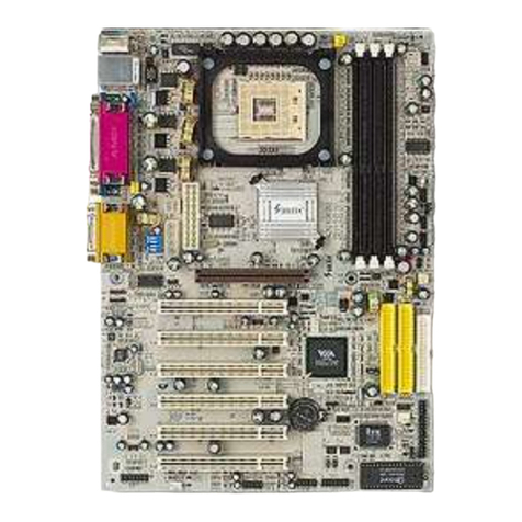
SOLTEK
SOLTEK SL-B9D-FGR User manual

SOLTEK
SOLTEK SL-63AV Use and care manual

SOLTEK
SOLTEK SL-65EB User manual

SOLTEK
SOLTEK B9A-FGR User manual

SOLTEK
SOLTEK SL-67EB Plus User manual

SOLTEK
SOLTEK SL-65F+ User manual

SOLTEK
SOLTEK SL-65EP User manual

SOLTEK
SOLTEK SL-PT880E-R User manual

SOLTEK
SOLTEK SL-65FVB User manual

SOLTEK
SOLTEK SL-67D User manual

SOLTEK
SOLTEK SL-75DRV2 User manual