manuals.online logo
Brands
  1. Home
  2. •
  3. Brands
  4. •
  5. SOMFY
  6. •
  7. Engine
  8. •
  9. SOMFY J4 1TN User manual

SOMFY J4 1TN User manual

1
© 2011 Somfy SAS. All rights reserved. 09/2011
DE
www.somfy.com
Motore J4 per veneziane da esterno
Ref. 5055337C
J4
1TN / 2TN
J4
HTM
J4
WT
Antrieb J4 für Außenjalousie / Raffstore
J4 motor for exterior Venetian Blinds
Moteur J4 pour brise soleil orientable
3RKRQ-SURYHQNRYQtåDOX]LHNotice dinstallation
1iYRGNSRXåLWtGuida all'installazione
Installation Guide
Gebrauchsanleitung
CZIT EN DE
FR
l5:$g&>m
12 © 2011 Somfy SAS. All rights reserved. 09/2011
EN
1. Glossary
Shaft adaptor Head rail adaptor
Power supply
connector
Shaft
Mushroom
Limit switch casing
Large acoustic strip
Gearbox
Brake
Rotor/Stator
*ORVVDU\2. General 19
3. Assembly 22
4. Electrical connection 27 71716HWWLQJWKHHQGOLPLWV6. HTM : Setting the end limits 29
7. WT : Setting the end limits 31
1. Glossaire 33
2. Généralités 34
3. Montage 37
4. Branchement électrique 42
5. 1TN / 2TN : réglage des fins de course 43
6. HTM : réglage des fins de course 44
7. WT : réglage des fins de course 46
1.1. EN - Contents
1.1. FR - Sommaire
*ORViĜ2. Veobecné pokyny 49
0RQWiå4. Electrické zapojení 57 3RKRQ\71711DVWDYHQtNRQFRYêFKSRORK6. Pohony HTM: Nastavení koncových poloh 59
7. WT: Nastavení koncových poloh 61
1.1. CZ - Obsah
1. Glossario 63
2. Informazioni generiche 64
3. Montaggio 67
4. Collegamento elettrico 72
5. 1TN/2TN: Regolazione dei finecorsa 73
6. HTM: Regolazione dei finecorsa 74
7. WT: Regolazione dei finecorsa 76
1.1. IT - Indice
1. Bezeichnungen 3
2. Allgemeines 4
3. Montage 7
4. Elektrischer anschluss 12
5. 1TN/2TN: Einstellen der endlagen 13
6. HTM : Einstellen der endlagen 14
7. WT : Einstellen der endlagen 16
1.1. DE - Inhalt
13
© 2011 Somfy SAS. All rights reserved. 09/2011
EN
Please read this installation guide carefully and in full in order to use the products functionalities
to their full extent. Somfy accepts no responsibility for any faults or damage resulting from failure
to adhere to the installation guide (use other than for the intended purpose, incorrect installation,
operating error etc.).
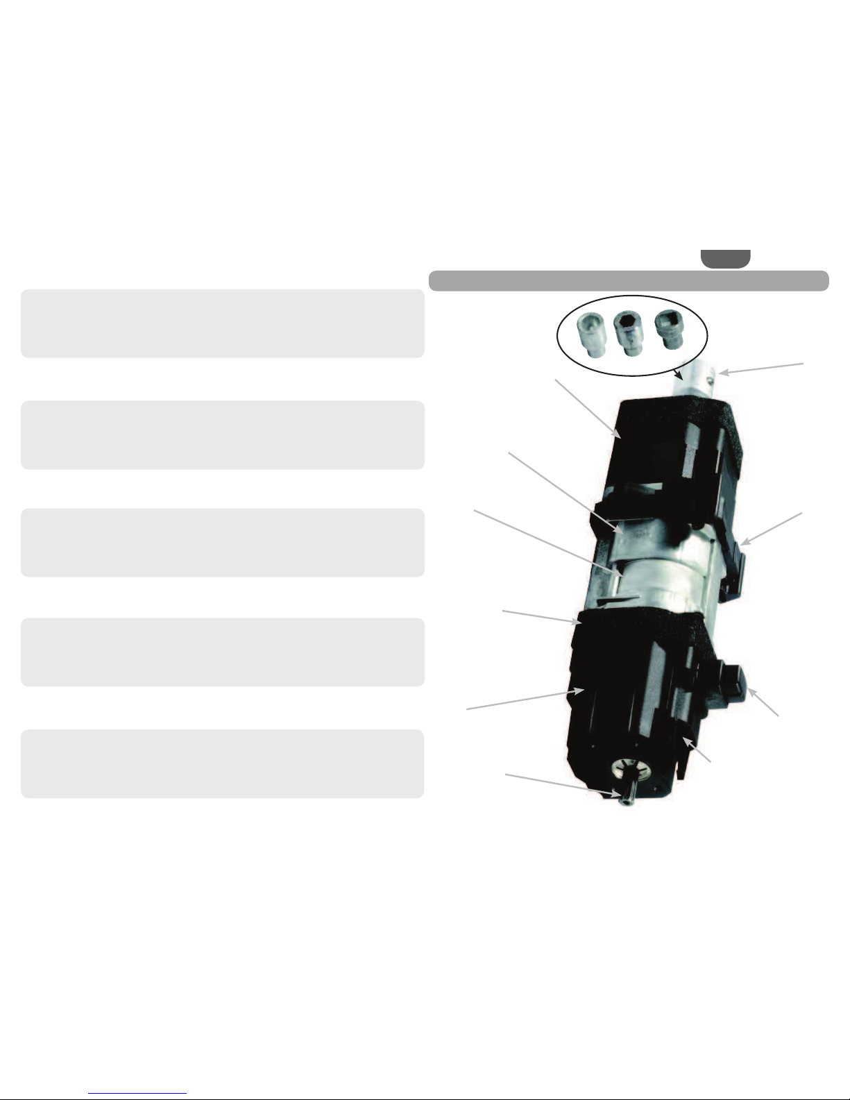
The J4 motor is designed for the electrical control of exterior Venetian blinds.
It is important to follow these instructions for the safety of all persons. Incorrect
assembly can lead to serious injury. These safety instructions must be retained.
The motor, torque and operating time must be adjusted according to the whole installation.
Only original Somfy accessories should be used (adaptors, brackets, same type of cable, etc.).
Fitting, testing, commissioning and repair of the installation must only be carried out by
qualified personnel.
Correct operation of the installation is only guaranteed if the installation and assembly
have been carried out according to best practices, if the power supply is adequate and if
maintenance is carried out.
The moving parts of the motors must be protected if operating below 2.50 m from ground level.
The installation must not be used if it shows any signs of damage (for example wear, damaged
cables/springs or misadjusted end limits).
The installation must be protected from all unauthorised use. Take preventive measures to
avoid any unwanted operation.
Children are not permitted to play with the wired controls. Keep the remote control out of the
reach of children.
Disconnect all connected cables from the power supply before working on the installation.
The permanently installed control points must be visible.
Do not use the installation if work (cleaning windows for example) is being carried out nearby.
Comply with the assembly and operating guides, in particular the safety instructions of the
manufacturer of the device to be used.
Subject to technical modifications.
SOMFY hereby declares that the device complies with the applicable directives.
A declaration of conformity is available at www.somfy.com/ce.
2. General
2.3.1. General information
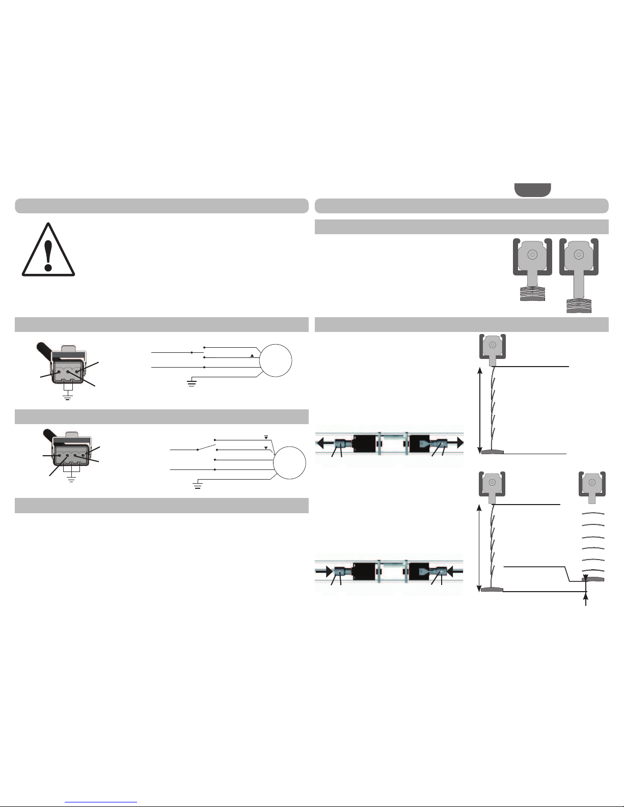
The main function of the mushroom is to ensure the safety of the installer and the end user, by
protecting the motor and the product on which it is installed.
For J4 1TN and J4 2TN motors, the mushroom must be used as an upper end limit.
For J4 HTM and J4 WT motors, the mushroom can be used as an upper end limit if the installer
does not want to adjust this position.
Be sure that during the operation, no slat of the end product exerts radial effort on the mus-
hroom, or the guide tube (if used).
7KHSXOOLQJRXWRIWKHDGMXVWDEOHH[WHQVLRQPDNHVWKHPRWRUXQXVDEOHGH¿QLWLYHO\2.3.2. Options
1TN / 2TN
HTM
2.1. General safety instructions
2.2. Declaration of conformity
2.3. Mushrooms
Black cover Ref. 9014160
Short (standard)
mushroom
With an adjustable
extension Ref.
With an adjustable
H[WHQVLRQ5HI+ 1 extension (2 max.)
Ref. 9014159
Short (standard)
mushroom
Ref. 9014233
With a long
mushroom
Ref. 9016331
With a long mushroom Ref. 9016331
+ 1 or 2 extensions Ref. 9014159
Black cover Ref. 9014160
With an adjustable extension
5HI+ 3 extension Ref. 9014159
+ 1 guide cable Ref. 9014229
14 © 2011 Somfy SAS. All rights reserved. 09/2011
EN
2.4.4. Thermal time
J4 1TN/2TN/HTM/WT motors are protected by a thermal cut-out in the event of a temperature rise
caused by continuous use, longer than 6 minutes.
2.4.5. Motor angle
The J4 motor is designed to operate in a horizontal position:
2.4.6. Direction of rotation
2.4.1. Cutaway diagram of the head rail
For detailed technical information, please refer to the appropriate data sheets and interface
drawings.
2.4.2. Applicable torque
2.4.3. Limit switch capacity
2.4. Technical data
Power supply 230 V ~ 50 Hz
Operating temperature - 20 °C à + 70 °C
Index protection rating IP 54
Safety level Classe I
Torque (Nm) 6 10 18
Power (W) 95 110 155
1TN
2TN
HTM
WT
R 13 max
36 mini
20 mini
26 mini
26 mini
Maximum applicable
torque/motor type
J406 J410 J418
For the J418 motor, the maxi-
mum torque on one shaft output
is 12N.m
6
N.m
10
N.m
18
N.m
Maximum
capacity
of the limit
switch unit
(in turns)
1TN 2TN HTM WT Factory-set
capacity
of the limit
switch unit
1TN 2TN HTM WT
60 60 90 200 60 60 60 120
NOT OK OK OK
10°
max
TopBottom
Power supply
connector
15
© 2011 Somfy SAS. All rights reserved. 09/2011
EN
3. Assembly
3.1.
[PPRU[PPKHDGUDLORSHQDWWKHERWWRP
3.2. [PPKHDGUDLORSHQDWWKHWRS3.3. [PPKHDGUDLORSHQDWWKHWRS1
2
1
3
7
7
2
1
2
1
3
7
7
2
1
2
1
3
7
7
2
5
6a 4
7
7
4
56a
4
7
7
5
56a
4
7
7
5
4
55
7
7
1
2
1
5
5
7
7
3
2
3.3.1. Assembly with external clips
Fit the 2 adaptors (1) using 2 M3x8 screws (2)
on the motor shaft.
)Tightening torque = 1.1 N.m
Connect the power supply cable (3) to the
motor.
Ensure that the cable does not hinder
the rotating part of the motor or the
Venetian mechanism.
Insert the motor in the head rail (4).
Using the clips (5), fix the motor in the head
rail (4) on top of the small acoustic strips (6a).
The shaft can be fixed in the adaptor using a
grub screw (7).
3.3.2. Assembly with internal clips
Fit the 2 adaptors (1) using 2 M3x8 screws (2)
on the motor shaft.
)Tightening torque = 1.1 N.m
Connect the power supply cable (3) to the
motor.
Ensure that the cable does not hinder
the rotating part of the motor or the
venetian mechanism.
Insert the motor in the head rail (4).
Using the clips (5), fix the motor in the head
rail (4).
The shaft can be fixed in the adaptor using a
grub screw (7).
Internal clips cannot be used with J418
motors (J4 motors with 18 N.m torque).
)LWWKHDGDSWRUVXVLQJ0[VFUHZVon the motor shaft.
)Tightening torque = 1.1 N.m
Connect the power supply cable (3) to the
motor.
Ensure that the cable does not hinder
the rotating part of the motor or the
Venetian mechanism.
,IQHFHVVDU\3UHVVWKHHGJHRIWKHKHDGUDLO(4) in the area of the motor.
Using the clips (5), fix the motor in the head
rail (4) on top of the small acoustic strips (6a).
The shaft can be fixed in the adaptor using a
grub screw (7).
3.2.1. Assembly with external clips
Fit the 2 adaptors (1) using 2 M3x8 screws (2)
on the motor shaft.
)Tightening torque = 1.1 N.m
Connect the power supply cable (3) to the
motor.
Ensure that the cable does not hinder
the rotating part of the motor or the
Venetian mechanism.
Insert the motor in the head rail (4).
Using the clips (5), fix the motor in the head
rail (4) on top of the small acoustic strips (6a).
The shaft can be fixed in the adaptor using a
grub screw (7).
16 © 2011 Somfy SAS. All rights reserved. 09/2011
EN
3.4.1. Assembly with J406/J410 motors (6 or
10 N.m torque)
)LWWKHDGDSWRUVXVLQJ0[VFUHZVon the motor shaft.
)Tightening torque = 1.1 N.m
Connect the power supply cable (3) to the
motor.
Ensure that the cable does not hinder
the rotating part of the motor or the
Venetian mechanism.
Fit the two head rail adaptors (8) on the motor.
Insert the motor in the head rail (4).
Using the clip (5), fix the motor in the head
rail (4).
The shaft can be fixed in the adaptor using a
grub screw (7).
;PPKHDGUDLORSHQDWWKHERWWRP3.4.2. $VVHPEO\ZLWK-PRWRUWRUTXH 1P)LWWKHDGDSWRUVXVLQJ0[VFUHZVon the motor shaft.
)Tightening torque = 1.1 N.m
Connect the power supply cable (3) to the
motor.
Ensure that the cable does not hinder
the rotating part of the motor or the
Venetian mechanism.
Fit the two head rail adaptors (8) on the motor.
Insert the motor in the head rail (4).
Using the clip (5), fix the motor in the head
rail (4).
The shaft can be fixed in the adaptor using a
grub screw (7).
Fit the additional bracket (9) on the head
rail (4) + motor assembly, as shown on the
diagram.
Fix the bracket (9) on the motor with an M5 x
10 mm screw.
)Tightening torque = 4 N.m aximum
)The screw must be fully tightened
on the bracket (9).
85
5
5
8
7
9
1
2
12
88
5
7
7
3
1
2
12
88
5
7
7
3
17
© 2011 Somfy SAS. All rights reserved. 09/2011
EN
)LWWKHDGDSWRUVXVLQJ0[VFUHZVon the motor shaft.
)Tightening torque = 1.1 N.m
Connect the power supply cable (3) to the
motor.
Ensure that the cable does not hinder
the rotating part of the motor or the
Venetian mechanism.
Fit the two head rail adaptors (8) on the motor.
Insert the motor in the head rail (4).
Using the clips (5), fix the motor in the head
rail (4).
;PPKHDGUDLORSHQDWWKHERWWRP
5
8
77
4
1
2
12
88
5
7
7
3
18 © 2011 Somfy SAS. All rights reserved. 09/2011
EN
Danger!
Live electric cables ÎDanger of electric shock if touched!
Disconnect all connected cables from the power supply before
working on the installation!
Take preventive measures to avoid any unwanted operation!
7KLV6RPI\SURGXFWPXVWEHLQVWDOOHGE\DWHFKQLFDOO\TXDOLILHGSHUVRQfor whom this guide is intended. The professionally qualified person must
comply with all the standards and legal provisions in force in the country of use.
The J4 power supply cable must never be powered while disconnected from the motor.
A J4 motor must never be supplied without its dedicated cable.
This motor must not be connected to an isolating transformer.
When you use a switch, a maximum of 3 motors, with a total cable length of 50 m, can be
connected in parallel.
The phases and neutrals must be connected together respectively.
Do not use more than one switch connected to each motor.
In case of drive by a controller or any automatisms, please refer to the dedicated instructions
manual.
The movement is correctly executed by the motor, only if it received a continuous order for at
least 200 ms.
For commands sent to the motor to be executed correctly, they must be at least 500 ms apart.
4. Electrical connection
4.1. 1TN / HTM / WT
4.2. 2TN
6SpFL¿FLWpV-:7The mushroom is used for the upper end limit position.
To adjust the height of the mushroom, use the extensions
described in section 2.3.
5. 1TN/2TN: Setting the end limits
5.1. Upper end limit position
5.2.
Lower end limit (1TN)/lower end limit no. 2 (2TN) position
The lower end limit position cannot be adjusted on
the motor. The motor is supplied ex. factory in the
lower end limit position.
To change the lower end limit position on
the exterior Venetian blind, use the following
procedure:
If necessary, loosen the grub screws (7), then
disconnect the drive shafts from the motor shaft
adaptors (1).
Rotate the motor downwards until it stops in the
lower end limit position.
Position the exterior Venetian blind in the
required lower end limit (1TN)/lower end limit
no. 2 (2TN) position.
Connect the drive shafts to the motor shaft
adaptors (1), then, if necessary, fully tighten the
screws (7).
The lower end limit position is now set.
M
Common
Neutral
Earth
Brown (3)
Black (2)
blue (1)
green-yellow
Motor connector
1 2 3
Neutral
(blue)
Bottom
(Brown)
Top
(Black)
Earth (green-yellow)
Motor
M
1 2 3 4
Bottom
slats open
(black)
Bottom slats
closed (Grey)
Neutral (bleu)
Top (Brown or
red)
Motor
Earth (green-yellow)
Common
Neutral
Earth
Grey (2)
Brown or red (3)
Black (1)
blue (4)
green-yellow
Motor connector
Lower end
limit position
1 TN
60 turns maximum
Upper end
limit position
2 TN
Upper end
limit position
Lower end limit
position no. 2 180°
60 turns maximum
Lower end limit
position no. 1
11
77
11
77
19
© 2011 Somfy SAS. All rights reserved. 09/2011
EN
%ULHÀ\SUHVVWKHOLPLWVHWWLQJEXWWRQXQWLOLWORFNVGRQRWNHHSLWKHOGLQOnly press the setting button for the corresponding direction (lower end
limit = white button, upper end limit = black button).
Never press both setting buttons at the same time.
Risk of damaging the motor (interlock mechanism)
Factory setting: The motor is supplied in lower end limit position with 60 turns to the upper
end limit.
The 2 end limit position setting operations described below are independent.
Move the exterior Venetian blind to at
least 30 cm (b) below the required upper
end limit (a).
Press the black setting button (c)
until it locks.
Move the exterior Venetian blind to the required
upper end limit position (momentary mode is possible).
Now move the exterior Venetian blind downwards
until you hear the button unlock (approximately 2 turns/4 seconds).
ÖThe upper end limit is now set.
Note: When the motor is turned upside down (mushroom upwards), the locking and unlocking of
the buttons can be seen.
6. HTM : Setting the end limits
6.1. Upper end limit Move the exterior Venetian blind to at least
30 cm (e) above the required lower
end limit (f).
Press the white setting button (d) until it
locks.
Move the exterior Venetian blind to the
required lower end limit position
(momentary mode is possible).
Now move the exterior Venetian blind upwards
until you hear the button unlock (approximately 2 turns/4 seconds).
ÖThe lower end limit is now set.
Note: When the motor is turned upside down (mushroom upwards),
the locking and unlocking of the buttons can be seen.
Perform a complete cycle, to check that the following settings are correct:
UUpper end limit position
ÖLower end limit position
ÖStop on mushroom, by resting against the mushroom during an upward movement.
6.2. Lower end limit
6.3. Test
c
a
> 30cm
b
e
> 30cm
f
d
20 © 2011 Somfy SAS. All rights reserved. 09/2011
EN
WT
RTS
A
By default (factory setting) the motor is supplied in lower end limit
position with 120 turns to the upper end limit position.
Connect the WT setting tool - Ref. 9013142.
Position the exterior Venetian blind in-between the preset end limit
positions.
Press the Ÿźbutton on the WT setting tool simultaneously for at
least 5 seconds.
)The exterior Venetian blind makes a brief movement wards.
If you do not have the WT setting tool, you can perform this
RSHUDWLRQE\SUHVVLQJWKHŸDQGźEXWWRQVRQDQRQORFNLQJGRXEOHpushbutton.
0RYHWKHH[WHULRU9HQHWLDQEOLQGXSZDUGVE\SUHVVLQJWKHŸEXWWRQ)7KHH[WHULRU9HQHWLDQEOLQGPRYHVXSZDUGVVWRSVEULHÀ\
(0.2 seconds) and then continues to move up. This brief stop
indicates that the J4 WT motor is in end limit setting mode.
&RQWLQXHWRSUHVVWKHŸEXWWRQXQWLOWKHUHTXLUHGXSSHUHQGOLPLWSRVLWLRQis reached.
6WRUHWKHXSSHUHQGOLPLWSRVLWLRQE\SUHVVLQJWKHźEXWWRQ)7KHH[WHULRU9HQHWLDQEOLQGPRYHVGRZQZDUGVVWRSVEULHÀ\(0.2 seconds) and then continues to move down. This brief
stop indicates that the J4 WT motor is no longer in end limit
setting mode and has stored the upper end limit position.
To set an end limit position again, go back to step 7.1.
During this setting operation, if the exterior Venetian blind moves up
until it rests against the mushroom, the upper end limit position is
automatically stored at approximately 5 mm below the position of the
mushroom.
1RWH<RXFDQH[LWWKLVPRGHGXULQJWKHVHWWLQJRSHUDWLRQE\EULHÀ\SUHVVLQJthe Ÿźbutton on the WT setting tool.
7. WT : Setting the end limits
7.1. Switching to end limit setting mode
7.2. Setting the upper end limit position 3HUIRUPVWHS0RYHWKHH[WHULRU9HQHWLDQEOLQGGRZQZDUGVE\SUHVVLQJWKHźEXWWRQ)7KHH[WHULRU9HQHWLDQEOLQGPRYHVGRZQZDUGVVWRSVEULHÀ\(0.2 seconds) and then continues to move down. This brief
stop indicates that the J4 WT motor is in end limit setting
mode.
&RQWLQXHWRSUHVVWKHźEXWWRQXQWLOWKHUHTXLUHGORZHUHQGOLPLWSRVLWLRQis reached.
6WRUHWKHORZHUHQGOLPLWSRVLWLRQE\SUHVVLQJWKHŸEXWWRQ)7KHH[WHULRU9HQHWLDQEOLQGPRYHVXSZDUGVVWRSVEULHÀ\
(0.2 seconds) and then continues to move up. This brief stop
indicates that the J4 WT motor is no longer in end limit setting
mode and has stored the lower end limit position.
To set an end limit position again, go back to step 7.1.
1RWH<RXFDQH[LWWKLVPRGHGXULQJWKHVHWWLQJRSHUDWLRQE\EULHÀ\SUHVVLQJthe Ÿźbutton on the WT setting tool.
Position the exterior Venetian blind in-between the preset end limit positions.
%ULHIO\SUHVVWKHźEXWWRQWait for at least 5 seconds, then press the mushroom DQGWKHŸEXWWRQRQWKHFRQWUROpoint simultaneously, for at least 5 seconds.
The exterior Venetian blind makes a brief movement upwards.
Carry out the procedure described in section 7.2 to set the upper end limit position.
Carry out the procedure described in section 7.3 to set the lower end limit position.
7.3. Setting the lower end limit position
7.4.
Setting the end limit positions without the WT setting tool
21
© 2011 Somfy SAS. All rights reserved. 09/2011
EN
Connect the WT setting tool - Ref. 9013142.
Ensure that the exterior Venetian blind is at least 30 cm below the stop on the mushroom
position.
Press the Ÿźbutton on the WT setting tool for 15 seconds.
)7KHPRWRUEULHÀ\URWDWHVWZLFH)The current position of the Venetian blind is stored as the lower position.
)The upper end limit position is stored at 120 turns above the lower end limit
position.
,I\RXGRQRWKDYHWKH:7VHWWLQJWRRO\RXFDQSHUIRUPWKLVRSHUDWLRQE\SUHVVLQJWKHŸDQGźEXWWRQVRQDQRQORFNLQJGRXEOHSXVKEXWWRQThe motor does not operate. Check:
That the motor wiring is correct
That the motor has not undergone a thermal cutout
)If it has, wait for the motor to cool down
That the appropriate cable has been used
That the motor used is definitely a J4 WT motor (read the label)
7.5. Return to factory mode
7.6. Troubleshooting

Other manuals for J4 1TN

3

This manual suits for next models

3

Other SOMFY Engine manuals

SOMFY Tilt & Lift 25 RTS Central User manual

SOMFY

SOMFY Tilt & Lift 25 RTS Central User manual

SOMFY Sonesse 40 RTS User manual

SOMFY

SOMFY Sonesse 40 RTS User manual

SOMFY Sonesse ULTRA 30 WireFree RTS Li-ion Operating instructions

SOMFY

SOMFY Sonesse ULTRA 30 WireFree RTS Li-ion Operating instructions

SOMFY Ilmo 40 WT User manual

SOMFY

SOMFY Ilmo 40 WT User manual

SOMFY Sonesse 40 RS485 User manual

SOMFY

SOMFY Sonesse 40 RS485 User manual

SOMFY sonesse 30 rts Installation manual

SOMFY

SOMFY sonesse 30 rts Installation manual

SOMFY Oximo 50 S auto RTS Assembly instructions

SOMFY

SOMFY Oximo 50 S auto RTS Assembly instructions

SOMFY ALTUS RTS Asia User manual

SOMFY

SOMFY ALTUS RTS Asia User manual

SOMFY J4 RTS Assembly instructions

SOMFY

SOMFY J4 RTS Assembly instructions

SOMFY Elite Smart Shades R28 WireFree RTS Operating instructions

SOMFY

SOMFY Elite Smart Shades R28 WireFree RTS Operating instructions

SOMFY PERGOLA 50 io RGS User manual

SOMFY

SOMFY PERGOLA 50 io RGS User manual

SOMFY ilmo 50 WT User manual

SOMFY

SOMFY ilmo 50 WT User manual

SOMFY GOME MOTION Roll Up 28 WT User manual

SOMFY

SOMFY GOME MOTION Roll Up 28 WT User manual

SOMFY LT50 RS485 User manual

SOMFY

SOMFY LT50 RS485 User manual

SOMFY Orea RTS User instructions

SOMFY

SOMFY Orea RTS User instructions

SOMFY J4 io Instruction Manual

SOMFY

SOMFY J4 io Instruction Manual

SOMFY Glydea ULTRA DIGITAL NETWORK Operating instructions

SOMFY

SOMFY Glydea ULTRA DIGITAL NETWORK Operating instructions

SOMFY Roll Up 28 WireFree RTS User manual

SOMFY

SOMFY Roll Up 28 WireFree RTS User manual

SOMFY LT50 Service manual

SOMFY

SOMFY LT50 Service manual

SOMFY sonesse 30 rts User manual

SOMFY

SOMFY sonesse 30 rts User manual

SOMFY Glydea Operating instructions

SOMFY

SOMFY Glydea Operating instructions

SOMFY LS 40 User manual

SOMFY

SOMFY LS 40 User manual

SOMFY RS-485 SDN 2.0 Quick setup guide

SOMFY

SOMFY RS-485 SDN 2.0 Quick setup guide

SOMFY Sunea 40 RTS DC User manual

SOMFY

SOMFY Sunea 40 RTS DC User manual

Popular Engine manuals by other brands

Flux FBM-B 3100 Original operating instructions

Flux

Flux FBM-B 3100 Original operating instructions

IQ Vertiq 8108 instruction manual

IQ

IQ Vertiq 8108 instruction manual

Polini THOR 190 HF Use and maintenance manual

Polini

Polini THOR 190 HF Use and maintenance manual

MTU MS150112/01E operating instructions

MTU

MTU MS150112/01E operating instructions

Briggs & Stratton 120000 Operator's manual

Briggs & Stratton

Briggs & Stratton 120000 Operator's manual

Iveco N67 ENT M45 Use and maintenance

Iveco

Iveco N67 ENT M45 Use and maintenance

Westerbeke 71 B-FOUR Service manual

Westerbeke

Westerbeke 71 B-FOUR Service manual

Fiamma 07779-01 Installation and usage instructions

Fiamma

Fiamma 07779-01 Installation and usage instructions

Chicago Pneumatic M39-1170-KSL ATEX user manual

Chicago Pneumatic

Chicago Pneumatic M39-1170-KSL ATEX user manual

Taidong TDME-3M78 Operation manual

Taidong

Taidong TDME-3M78 Operation manual

Assun AM-PI3675AN Series product manual

Assun

Assun AM-PI3675AN Series product manual

MTU 12 V 2000 M92 operating instructions

MTU

MTU 12 V 2000 M92 operating instructions

Siemens SIMOTICS 1FT2104-4AF Configuration manual

Siemens

Siemens SIMOTICS 1FT2104-4AF Configuration manual

Volvo Penta V8-225-CE Operator's manual

Volvo Penta

Volvo Penta V8-225-CE Operator's manual

Predator Engines Pacific Hydrostar 212cc Gasoline Powered Clear Water... Owner's manual & safety instructions

Predator Engines

Predator Engines Pacific Hydrostar 212cc Gasoline Powered Clear Water... Owner's manual & safety instructions

QUICK-ROTAN MINI-STOP Q41MSII instruction manual

QUICK-ROTAN

QUICK-ROTAN MINI-STOP Q41MSII instruction manual

O.S. engine FS-40S-C Owner's instruction manual

O.S. engine

O.S. engine FS-40S-C Owner's instruction manual

STEYR MO156K25 Operation, maintenance and warranty manual

STEYR

STEYR MO156K25 Operation, maintenance and warranty manual

manuals.online logo
manuals.online logoBrands
  • About & Mission
  • Contact us
  • Privacy Policy
  • Terms and Conditions

Copyright 2025 Manuals.Online. All Rights Reserved.