manuals.online logo
Brands
  1. Home
  2. •
  3. Brands
  4. •
  5. SOMFY
  6. •
  7. Engine
  8. •
  9. SOMFY J4 WT User manual

SOMFY J4 WT User manual

© by Somfy GmbH Rev. 01-08/2011 vm Technische Änderungen bleiben vorbehalten
Achtung: Für die Sicherheit von Personen ist es wichtig, diese Anweisungen zu befolgen. Falsche Montage kann zu ernsthaften Verletzungen
führen. Diese Sicherheitshinweise sind aufzubewahren.
- Der Antrieb, das Drehmoment und die Laufzeit müssen auf die Gesamtanlage abgestimmt sein.
- Es darf nur Original Somfy Zubehör verwendet werden (Adapter, Lager, Stecker, ...).
- Errichten, Prüfen, in Betrieb setzen und Fehlerbehebung der Anlage darf nur von einer qualifizierten Person durchgeführt werden.
- Der ordnungsgemäße Betrieb der Anlage ist nur bei fachgerechter Installation, Montage, ausreichender Stromversorgung und Wartung gewährleistet.
- Bei Anzeichen von Beschädigungen (z.B. Verschleiß, beschädigte Kabel und Federn oder verstellte Endlagen) darf die Anlage nicht benutzt werden.
- Vor Arbeiten an der Anlage sind alle Anschlussleitungen spannungslos zu schalten.
- Beachten sie die Montage- und Bedienungsanleitungen, insbesondere die Sicherheitshinweise des Herstellers der zu betreibenden Einrichtung..
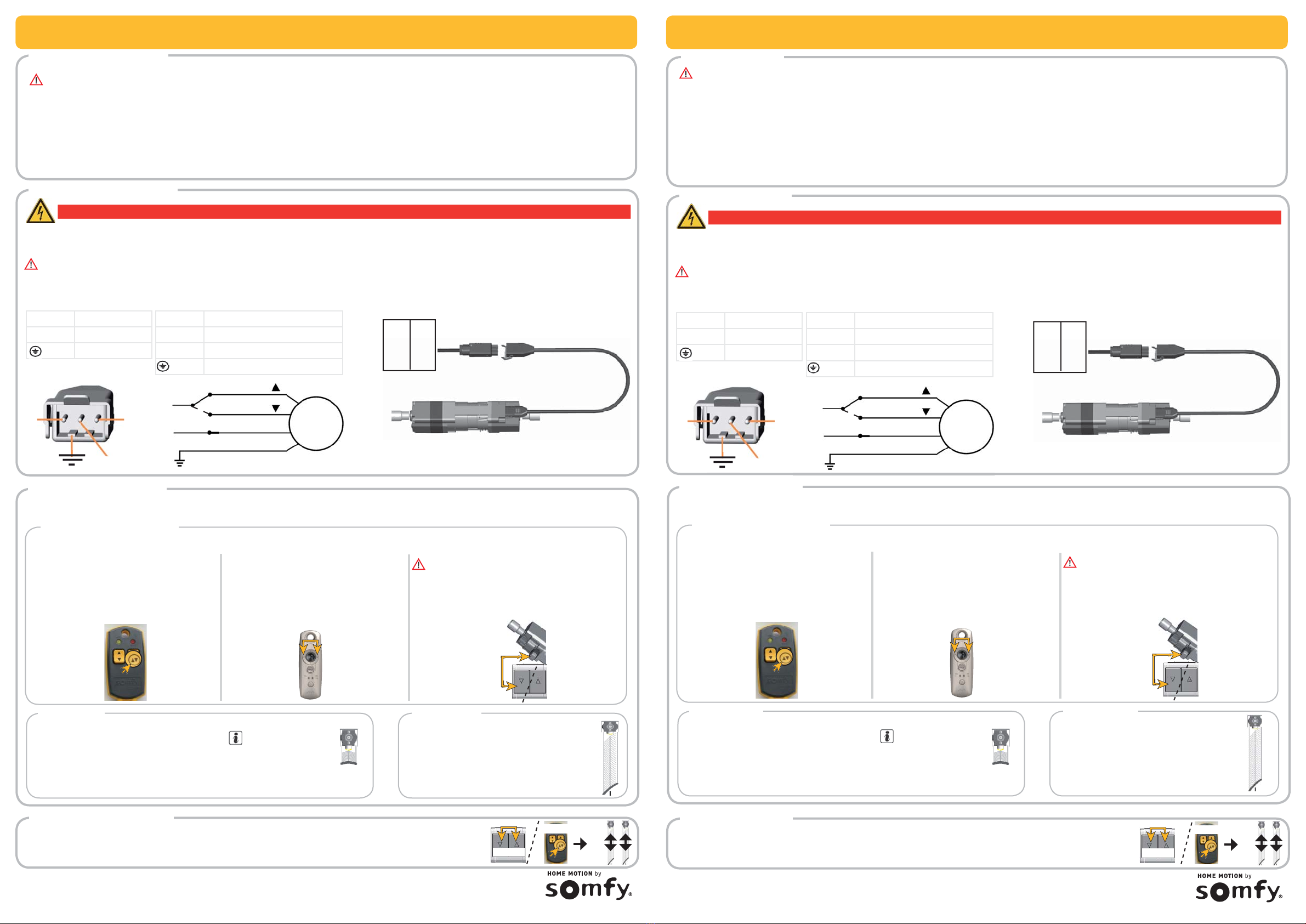
1 = N Neutralleiter / blau
2 = Auf / schwarz
3 = Ab / braun
= Schutzleiter / gelb-grün
Elektrischer Anschluß
Achtung: ●Dieses Produkt muss von einer fachlich qualifizierten Person (Elektrofachkraft nach DIN VDE 1000-10) installiert werden.
●Die fachlich qualifizierte Person muss alle im Installationsland geltenden Normen und Gesetze befolgen.
●Bei Drehrichtungsänderung muss die Umschaltverzögerung mind. 500 ms (spannungsfrei) betragen.
●Einschaltverzögerung des Antriebs: max. 200 ms
●Parallelschaltung: bis 3 Antriebe (max. Kabellänge 50m)
Gefahr
Offen liegende Spannungsleitungen Berührungsgefahr, Stromschlag
Schalten Sie alle zu montierenden Anschlussleitungen spannungslos! Treffen Sie Sicherheitsvorkehrungen gegen unbeabsichtigtes Einschalten.
Antrieb
M
N
L
2
3
1
L = Phase
N = Neutralleiter
= Schutzleiter
▲▼
Umschaltverzögerung:
mind. 500 ms (spannungsfrei)
Verriegelte Schalter/
Taster/Steuerungen
1
2
3
Stecker antriebsseitig
Sicherheitshinweise
DE - Kurzanleitung
© by Somfy GmbH Rev. 01-08/2011 vm Technical changes remain reserving
Attention: For safety reasons, please read the this instruction carefully. Wrong assembly can lead to serious injuries. These safety advices are to be kept.
- The motor, torque and operating time must be adjusted according to the complete installation.
- Only Somfy original accessories should be used (adapters, brackets, connectors, power cable, etc.).
- Fitting, testing, commissioning and repair of the installation must only be carried out by qualified personnel.
- Correct operation is only guaranteed if the installation and assembly have been carried out according to best practices, if the electrical supply is adequate
and if maintenance is carried out.
- The installation must not be used if it shows any signs of damage (for example wear, damaged cables and springs or ill adjusted end limits).
- Disconnect all the connection cables from the power supply before operating on the installation.
- Observe the assembly and use guidelines, in particular the safety instructions from the manufacturer of the device to be used..
1 = N Neutral / blue
2 = Up / black
3 = Down / braun
= Earth / yellow-green
Electrical wiring
Attention: ●These product must be installed and programmed by a qualified installer for whom these instructions are intended.
●The installer must comply with current standards and legislation in the country in which the product is being installed.
●During change of direction of rotation the switching delay must amount to at least 500 ms (unstressed).
●Starting delay of the motor: max. 200 ms
●Parallel connection: up to 3 motor (max. length ot the cable 50m)
Danger
230V~ Blank wiring touch danger, electric shock
Switch of all supply lines for the intended installation! Fulfill all safety precautions to protect against unintentional switching on.
Motor
M
N
L
2
3
1
L = Live
N = Neutral
= Earth
▲▼
switch over delay:
min. 500 ms (unstressed)
Locked switches/
Switches/Controller
1
2
3
Plug motor side
Safety advices
EN - Summary instruction
J4 WT J4 WT
a
Endlageneinstellung
Werkseinstellung: Der Antrieb wird in der unterern Endlage mit 120 von max. 200 Umdrehungen bis zur obere Endlage ausgeliefert.
Obere Endlage Untere Endlage
●Jetzt AUF-Taste drücken.
Der Behang fährt an, stoppt
●AUF-Taste weiter betätigen, bis gewünschte
obere Endlage erreicht ist.
●AB-Taste drücken.
Die neue obere Endlage ist gespeichert


●Jetzt AB-Taste drücken.
Der Behang fährt an, stoppt und fährt weiter
in AB-Richtung.
●AB-Taste gedrückt halten, bis gewünschte
untere Endlage erreicht ist.
●AUF-Taste drücken.
Die neue untere Endlage ist gespeichert
Wird der Schalt-
fühler während der
Einstellung betätigt,
wird die Position direkt
unterhalb als obere
Endlage gespeichert.
Antrieb zurücksetzen
2 X
bis
ca. 15 s
ca. 15 s
Drücken Sie die AUF- und AB- Taste gleichzeitig bzw. die WT Taste am Einstellkabel ca. 15 Sekunden lang, bis der
Antrieb mit 2 Bewegungen bestätigt. Die aktuelle Position wird als untere Endlage gespeichert.
Reset the motor
2 X
bis
ca. 15 s
ca. 15 s
Press the UP and DOWN button at the same time or the WT button of the setting tool approx. 15 s long, until the
motor confirms with 2 movements. The current position is stored as lower end stop.
Aktivieren des Einstellmodus
Führen Sie zum Aktivieren des Einstellmodus nur eine der 3 unten aufgeführten Aktionen durch: oder oder 
WT Taste am Einstellkabel 5s drücken.
Der Behang fährt kurz in AUF-Richtung.
AUF- und AB-Taste am Funkhandsender
(nur in Verbindung mit Soliris Mod/Var Slim
Receiver RTS ab Vers.B00) 8s gleichzeitig
drücken.
Der Behang fährt kurz in AUF-Richtung.
Letzer Befehl muss AB-Richtung gewesen sein
und Position Behang mittig!
AUF- oder AB-Taste am vorhandenen Schalter gleich-
zeitig mit dem Schaltfühler des Antriebs für 5s drücken.
Der Behang fährt kurz in AUF-Richtung.
End limit settings
Upper end stop Lower end stop
●Now press the UP button.
The blind starts, stops and continues drive
into up direction.
●Keep the UP button pressed, until the desired
upper end stop is reached.
●Briefly press the DOWN button.
The new upper end stop is programmed.


●Now press the DOWN button.
The blind starts, stops and continues drive
into down direction.
●Keep the DOWN button pressed, until the
desired lower end stop is reached.
●Briefly press the UP button.
The new lower end stop is programmed.
If the switching
tracer is oper-
ated during the setting,
the position is stored
directly below as upper
end position.
Activate the setting mode
For activating the setting mode use only one of the 3 actions specified down through: or or 
Press the WT button on the setting tool for 5s.
The blind drives briefly in UP direction.
Simultaneously press the UP and DOWN
button on the remote control (only with the
Soliris Mod/Var Slim Receiver RTS from
version.B00 on) for 8s.
The blind drives briefly in UP direction
Last order must have been in down direction. The
blind position has to be centrically!
Simultaneously press the UP or DOWN button on an
existing switch together with the switching tracer for 5s.
The blind drives briefly in UP direction.
Factory settings: The motor is delivered in the his lower end stop with 120 of max.200 revolutions into the upper end stop.
© by Somfy GmbH Rev. 01-08/2011 vm Sous réserve de modifications techniques
Attention: Pour la sécurité des personnes, il est essentiel de suivre les instructions (à conserver) ci-dessous. Un mauvais montage peut engen-
drer des blessures importantes
- Le moteur, le couple et le temps de fonctionnement doivent être ajustés en fonction de l‘installation complète.
- Seuls les accessoires d‘origine SOMFY doivent être utilisés (adaptateurs, supports, connecteurs, câble d’alimentation,...).
- La mise en place, le contrôle, la mise en service et le dépannage de l‘installation ne doivent être effectués que par le personnel qualifié
- Le fonctionnement correct de l‘installation n‘est garanti que si l‘installation et le montage ont été réalisés dans les règles de l‘art.
- L‘installation ne doit pas être utilisée si elle présente des signes d‘endommagement (par exemple usure, câbles et ressorts endommagés ou fins de course déréglées).
- Débranchez tous les câbles de raccordement de l‘alimentation électrique avant d‘intervenir sur l‘installation.
- Respectez les notices de montage et d‘utilisation, en particulier les consignes de sécurité du fabricant de BSO à utiliser...
1 = N Neutre / bleu
2 = Montée / noir
3 = Descente / brun
= Terre / vert-Jaune
Câblage
Attention: ●L’installation de ce produit est seulement réservée aux personnes qualifiées, respectant les lois et normes en vigueur dans le
pays d’installation.
●Temporisation recommandée pour le moteur pour le changement de direction: au moins 500ms (sans courant).
●Temporisation recommandée pour le moteur au démarrage: au moins 200ms.
●Un maximum de 3 moteurs, avec une longueur totale de câble de 50m, peuvent être branchés en parallèle.
Danger
Câbles nus 230V > risques de contact et d‘électrocution
Couper l‘alimentation secteur de toutes les installations en cours de câblage et prenez les mesures pour éviter toute mise en marche intempestive
moteur
M
N
L
2
3
1
L = Phase
N = Neutre
= Terre
▲▼
Changement de direction:
au moins 500 ms (sans courant)
Inverseur
1
2
3
Fiche moteur
Consignes de sécurité
FR - Notice courte
J4 WT
DE Kurzanleitung
www.somfy.de Somfy GmbH
Felix-Wankel-Straße 50
72108 Rottenburg / N
Tel.: +49 (0) 18 05 / 25 21 31 • Fax.: +49 (0) 18 05 / 25 21 32
(0,14€/min. aus dem dt. Festnetz, Mobilfunk max. 0,42 €/min.)
e-mail: service@somfy.de
www.somfy.de
J4 WT
EN Summary instruction
FR Notice courte
Réglage d‘usine: Le moteur est livré en fin de course basse et avec 120 (de 200 max) tours d’arbre moteur jusqu’à sa fin de course haute (si non
limitée par le palpeur du moteur).
Ref.: 5 072 510
Réinitialisation du moteur
2 X
bis
ca. 15 s
ca. 15 s
Appuyer les touches «Montée» et «Descente» simultanément ou bien Touche WT (Câble de réglage) pendant env 15
sec jusqu’à ce que le BSO confirme par deux mouvements. La position actuelle est alors enregistrée en tant que fin
de course basse.
Réglages des fins de course
Fin de course haute Fin de course basse
●Appuyer maintenant sur la touche “Montée”.
Le BSO confirme par un bref mouvement vers le haut.
●Actionner la touche “Montée” jusqu’à obtention de la fin de
course haute désirée.
●Appuyer sur la touche “Descente”.
Le BSO confirme par un bref mouvement que la nouv-
elle fin de course haute est enregistrée.


●Appuyer maintenant sur la touche “Descente”.
Le BSO confirme par un bref mouvement
vers le haut.
●Actionner la touche “Descente” jusqu’à obten-
tion de la fin de course basse désirée.
●Appuyer sur la touche “Montée”.
Le BSO confirme par un bref mouvement que
la nouvelle fin de course basse est enregistrée.
Si lors de cette
procédure, le pal-
peur est actionné, la
nouvelle fin de course
haute se situe à env
1 cm en dessous de
celui ci.
Activer le mode programmation
Pour activer le mode programmation, utiliser seulement l’une des 3 possibilités suivantes:: ou ou 
Presser la touche WT du cable de régalge
pendant 5s.
Le BSO confirme par un bref mouvement
vers le haut.
Presser simultanément «Montée» et «Des-
cente» pendant 8s sur la télécommande
(seulement avec Recépteur Soliris Mod/Var
Slim Rec RTS version B00)
Le BSO confirme par un bref mouvement
vers le haut.
A condition que le BSO est en position verticale mé-
diane et que le dernier ordre a été du type descente!
Appuyer simultanément sur le palpeur du moteur ET
soit la touche «Montée» ou soit «Descente» de l’inter-
rupteur existant
Le BSO confirme par un bref mouvement
vers le haut.
SOMFY GmbH
Johann-Herbst-Str. 23
A-5061 Elsbethen-Glasenbach
Tel.: +43 (0)662 625308 0
Fax.: +43 (0)662 625308 22
e-mail: office@somfy.at
www.somfy.at
Somfy AG
Vorbuchenstrasse 17
CH-8303 Bassersdorf
Telefon +41 (0) 44 838 40 30
Fax +41 (0) 44 836 41 95
e-mail: support@somfy.ch
www.somfy.ch

Other manuals for J4 WT

6

Other SOMFY Engine manuals

SOMFY Tilt & Lift 25 RTS Central User manual

SOMFY

SOMFY Tilt & Lift 25 RTS Central User manual

SOMFY Sonesse 40 RS485 User manual

SOMFY

SOMFY Sonesse 40 RS485 User manual

SOMFY Tilt Only 50 WF RTS User manual

SOMFY

SOMFY Tilt Only 50 WF RTS User manual

SOMFY Tilt & Lift 25 RTS Central User manual

SOMFY

SOMFY Tilt & Lift 25 RTS Central User manual

SOMFY SUNEA CSI RTS User manual

SOMFY

SOMFY SUNEA CSI RTS User manual

SOMFY ilmo 50 WT User manual

SOMFY

SOMFY ilmo 50 WT User manual

SOMFY Sonesse 40 RTS User manual

SOMFY

SOMFY Sonesse 40 RTS User manual

SOMFY LS 40 User manual

SOMFY

SOMFY LS 40 User manual

SOMFY ILMO WT Operating manual

SOMFY

SOMFY ILMO WT Operating manual

SOMFY Sonesse 50 Operating instructions

SOMFY

SOMFY Sonesse 50 Operating instructions

SOMFY Glydea Ultra RTS Series User manual

SOMFY

SOMFY Glydea Ultra RTS Series User manual

SOMFY Sonesse 50 PA User manual

SOMFY

SOMFY Sonesse 50 PA User manual

SOMFY WireFree RTS Operating instructions

SOMFY

SOMFY WireFree RTS Operating instructions

SOMFY J4 1TN User manual

SOMFY

SOMFY J4 1TN User manual

SOMFY Sonesse 30 PoE Operating instructions

SOMFY

SOMFY Sonesse 30 PoE Operating instructions

SOMFY ST50 User guide

SOMFY

SOMFY ST50 User guide

SOMFY Movelite WireFree RTS User manual

SOMFY

SOMFY Movelite WireFree RTS User manual

SOMFY Sonesse 40 PA User manual

SOMFY

SOMFY Sonesse 40 PA User manual

SOMFY Sonesse ULTRA 30 WF Zigbee Li-ion User manual

SOMFY

SOMFY Sonesse ULTRA 30 WF Zigbee Li-ion User manual

SOMFY GOME MOTION Roll Up 28 WT User manual

SOMFY

SOMFY GOME MOTION Roll Up 28 WT User manual

SOMFY ilmo 50 WT User manual

SOMFY

SOMFY ilmo 50 WT User manual

SOMFY SGH RTS User manual

SOMFY

SOMFY SGH RTS User manual

SOMFY Altus User manual

SOMFY

SOMFY Altus User manual

SOMFY LS 40 User manual

SOMFY

SOMFY LS 40 User manual

Popular Engine manuals by other brands

TecBrake T430A instruction manual

TecBrake

TecBrake T430A instruction manual

ZIEHL-ABEGG ZAtop SM210.60 operating instructions

ZIEHL-ABEGG

ZIEHL-ABEGG ZAtop SM210.60 operating instructions

ST WBE120LS Operator's manual

ST

ST WBE120LS Operator's manual

Vetus M2.C5 Operation manual

Vetus

Vetus M2.C5 Operation manual

WinGD X72-B Operation manual

WinGD

WinGD X72-B Operation manual

Atlas Copco LZB33-LB-AR0026-11 ATEX Safety information

Atlas Copco

Atlas Copco LZB33-LB-AR0026-11 ATEX Safety information

Belimo KM24-SR Information

Belimo

Belimo KM24-SR Information

Proteco PSE30 installation manual

Proteco

Proteco PSE30 installation manual

GE Pegasus MHV EP-427-I instructions

GE

GE Pegasus MHV EP-427-I instructions

Caple INCH Technical manual

Caple

Caple INCH Technical manual

DITEC PS-200 instruction manual

DITEC

DITEC PS-200 instruction manual

Briggs & Stratton 127800 Series Illustrated parts list

Briggs & Stratton

Briggs & Stratton 127800 Series Illustrated parts list

Porsche M 44/01 Workshop manual

Porsche

Porsche M 44/01 Workshop manual

Anhui Chery Automobile CAC478 Instruction Book on Using and Maintenance

Anhui Chery Automobile

Anhui Chery Automobile CAC478 Instruction Book on Using and Maintenance

Wyco EZ Vibe EH035 Operation, maintenance and parts manual

Wyco

Wyco EZ Vibe EH035 Operation, maintenance and parts manual

IMS MDrive23 Product data

IMS

IMS MDrive23 Product data

Rover K Series 1.8 VVC Workbook

Rover

Rover K Series 1.8 VVC Workbook

WÜRGES HVE 2 operating instructions

WÜRGES

WÜRGES HVE 2 operating instructions

manuals.online logo
manuals.online logoBrands
  • About & Mission
  • Contact us
  • Privacy Policy
  • Terms and Conditions

Copyright 2025 Manuals.Online. All Rights Reserved.