manuals.online logo
Brands
  1. Home
  2. •
  3. Brands
  4. •
  5. SSS Siedle
  6. •
  7. Intercom System
  8. •
  9. SSS Siedle ZFB 611-0 User manual

SSS Siedle ZFB 611-0 User manual

Other SSS Siedle Intercom System manuals

SSS Siedle IQ HTA User manual

SSS Siedle

SSS Siedle IQ HTA User manual

SSS Siedle HT 840-0 User manual

SSS Siedle

SSS Siedle HT 840-0 User manual

SSS Siedle BTS 850-02 User manual

SSS Siedle

SSS Siedle BTS 850-02 User manual

SSS Siedle BTC 850-0 User manual

SSS Siedle

SSS Siedle BTC 850-0 User manual

SSS Siedle Siedle-Classic CL 111 Series User manual

SSS Siedle

SSS Siedle Siedle-Classic CL 111 Series User manual

SSS Siedle iDorSS-5100 User manual

SSS Siedle

SSS Siedle iDorSS-5100 User manual

SSS Siedle DoorCom IP DCIP 650-0 User manual

SSS Siedle

SSS Siedle DoorCom IP DCIP 650-0 User manual

SSS Siedle CV 850-1-04 E User manual

SSS Siedle

SSS Siedle CV 850-1-04 E User manual

SSS Siedle BVPS 850-0 User manual

SSS Siedle

SSS Siedle BVPS 850-0 User manual

SSS Siedle SET CV 850-01 User manual

SSS Siedle

SSS Siedle SET CV 850-01 User manual

SSS Siedle BVI 750-0 Assembly instructions

SSS Siedle

SSS Siedle BVI 750-0 Assembly instructions

SSS Siedle Compact CV 850-1 User manual

SSS Siedle

SSS Siedle Compact CV 850-1 User manual

SSS Siedle AFSV 870-0 User manual

SSS Siedle

SSS Siedle AFSV 870-0 User manual

SSS Siedle AFS 870-0 User manual

SSS Siedle

SSS Siedle AFS 870-0 User manual

SSS Siedle Compact CV 850-1-02 E User manual

SSS Siedle

SSS Siedle Compact CV 850-1-02 E User manual

SSS Siedle SET CVB 850-1 E/W User manual

SSS Siedle

SSS Siedle SET CVB 850-1 E/W User manual

SSS Siedle BTSV 850-0 User manual

SSS Siedle

SSS Siedle BTSV 850-0 User manual

SSS Siedle SET CA 812 Series User manual

SSS Siedle

SSS Siedle SET CA 812 Series User manual

SSS Siedle ZPS 850-0 User manual

SSS Siedle

SSS Siedle ZPS 850-0 User manual

SSS Siedle BTSV 850-03 User manual

SSS Siedle

SSS Siedle BTSV 850-03 User manual

SSS Siedle BNS 750-02 User manual

SSS Siedle

SSS Siedle BNS 750-02 User manual

SSS Siedle NG 706-30-0 User manual

SSS Siedle

SSS Siedle NG 706-30-0 User manual

SSS Siedle Classic Camera 130 User manual

SSS Siedle

SSS Siedle Classic Camera 130 User manual

SSS Siedle BFC 850 series User manual

SSS Siedle

SSS Siedle BFC 850 series User manual

Popular Intercom System manuals by other brands

Videx VRDK1 (25H) Technical manual

Videx

Videx VRDK1 (25H) Technical manual

Auta COMPACT VISUALTECH manual

Auta

Auta COMPACT VISUALTECH manual

Aiphone LC-10S instructions

Aiphone

Aiphone LC-10S instructions

Aiphone PD-1 instructions

Aiphone

Aiphone PD-1 instructions

Aiphone JF-DVF-HID-I instructions

Aiphone

Aiphone JF-DVF-HID-I instructions

Comelit 4893M Technical manual

Comelit

Comelit 4893M Technical manual

MGL Avionics V16 manual

MGL Avionics

MGL Avionics V16 manual

urmet domus AIKO 1716/1 quick start guide

urmet domus

urmet domus AIKO 1716/1 quick start guide

urmet domus IPerVoice 1039 Installation

urmet domus

urmet domus IPerVoice 1039 Installation

Alpha Communications STR QwikBus TT33-2 Installation, programming, and  user's manual

Alpha Communications

Alpha Communications STR QwikBus TT33-2 Installation, programming, and user's manual

Monacor ICM-20H instruction manual

Monacor

Monacor ICM-20H instruction manual

Logenex A202CR Installation & programming

Logenex

Logenex A202CR Installation & programming

Quantum QR5 Installation and programming manual

Quantum

Quantum QR5 Installation and programming manual

EVGA XR1 quick guide

EVGA

EVGA XR1 quick guide

CyberData 011211 series Installation quick reference

CyberData

CyberData 011211 series Installation quick reference

Vidos duo M1021 user manual

Vidos

Vidos duo M1021 user manual

Savant DOR-SMS-00 Deployment guide

Savant

Savant DOR-SMS-00 Deployment guide

Dahua VTO Series quick start guide

Dahua

Dahua VTO Series quick start guide

manuals.online logo
manuals.online logoBrands
  • About & Mission
  • Contact us
  • Privacy Policy
  • Terms and Conditions

Copyright 2025 Manuals.Online. All Rights Reserved.

Produktinformation
Zubehör-Frontplatten-
befestigung
Product information
Front panel fastening
accessory
Information produit
Accessoires de xation
des façades
Opuscolo informativo
sulprodotto
Accessorio ssaggio
frontalino
Productinformatie
Accessoire frontpaneel-
bevestiging
Produktinformation
Tilbehør-beslag til front-
plademontage
Produktinformation
Tillbehör frontplåtsfäste
ZFB 611-0
2
1 2
3 5
6
„a“
3
Deutsch
Anwendung
Zubehör Frontplattenbefestigung zur
Montage einer Vario-TL-Lösung in
bauseitigen Frontplatten, Türseiten-
teilen etc.
Zulässige Wandstärke der bausei-
tigen Frontblende von 3 bis 30 mm.
Inhalt: 4 Metallbügel und 8 Befestig-
ungsschrauben zur Kombination
von VA/GU 5... in Verbindung mit
Montagerahmen und jeweiligen
Kombirahmen.
Um den Türlautsprecher zu
montieren, werden außer einem
Montagerahmen MR 611-... ein
Kombirahmen KR 611-... und ein
entsprechend großer Vario-Adapter
VA/GU 5...-0 noch benötigt.
Wichtig!
Der Montageraum muss von hinten
zugängig sein!
Montage
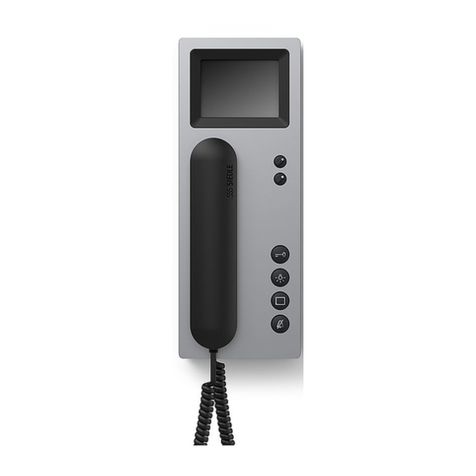
1 Metallbügel mit den beiliegenden
kurzen Schrauben auf der Rückseite
des VA/GU 5...-0 so montieren, dass
diese noch etwas bewegt werden
können.
2 Die vier roten Befestigungsteile “a“
auf dem VA/GU 5...-0 ausrichten.
3 Montagerahmen MR 611-... mit
dem entsprechenden Kombirahmen
KR 611-... auf das VA/GU 5...-0
aufsetzen und in den Ecken mit
den beiliegenden Schnellverschluss-
Schrauben befestigen.
4 (Ohne Abbildung)
Ausschnittsmaße (B x L) vom zu
montiernden VA/GU 5...-0
abnehmen und Ausschnitt her-
stellen.
5 Die zusammengebaute Kombina-
tion von vorne waagerecht oder
senkrecht in die Frontplatte ein-
setzen.
6 Metallbügel auf der Rückseite wie
dargestellt ausklappen, die 4 langen
Befestigungsschrauben eindrehen
und gegen die Frontplatte fest ver-
schrauben.
Application
Front panel fastening accessory for
mounting a Vario DL solution in
existing front panels, door side ele-
ments etc.
Admissible wall thickness from 3 to
30 mm.
Set contains: 4 metal brackets and
8 fastening screws for combination
of VA/GU 5... in conjunction with
mounting frame and relevant combi-
nation frame.
In order to mount the door loud-
speaker, apart from the mounting
frame MR 611-..., a combination
frame KR 611-... and a suitably
sized Vario adapter VA/GU 5...-0 are
required.
Important!
The mounting frame must offer
access from behind!
Mounting
1 Mount the metal brackets onto
the back of the VA/GU 5...-0 using
the provided short screws in such
a way that they still permit slight
movement.
2 Align the four red xing elements
“a“ on the VA/GU 5...-0.
3 Position the mounting frame
MR 611-... using the relevant com-
bination frame KR 611-... on the
VA/GU 5...-0 and fasten in the cor-
ners with the enclosed quick-closing
screws.
4 (not illustrated)
Take the recess dimensions (W x L)
from the VA/GU 5...-0 you intend to
mount and make the recess.
5 Insert the assembled combination
from the front horizontally or verti-
cally into the front panel.
6 Unhinge the metal bracket on the
back as illustrated, screw in the 4
long xing screws and screw rmly
against the front panel.
English
Application
Accessoires de xation des façades
pour le montage d‘une solution pla-
tine de rue Vario dans des façades
prévues sur site, éléments latéraux
de portes etc.
Epaisseur mur admissible du cache
frontal prévu sur site, de 3 à 30 mm.
Contenu : 4 brides métalliques et 8
vis pour xer la combinaison
VA/GU 5... en liaison avec cadres de
montage et cadres combinés corres-
pondants.
Pour monter le portier électrique, il
faut, en plus d‘un cadre de montage
MR 611-..., un cadre combiné
KR 611-... et un adaptateur Vario
VA/GU 5...-0 de taille correspon-
dante.
Important!
Le cadre de montage doit être acces-
sible de l‘arrière!
Montage
1 Monter les étriers métalliques sur
la face arrière du VA/GU 5...-0 avec
les vis courtes jointes sans les serrer
à fond.
2 Aligner les quatre pièces de xa-
tion rouges “a“ du VA/GU 5...-0.
3 Placer le cadre de montage
MR 611-... avec le cadre combiné
correspondant sur le VA/GU 5...-0
et le xer aux coins avec les vis de
xation rapide jointes.
4 (Sans illustration)
Mesurer les cotes à découper (lar-
geur x longueur) sur le VA/GU 5...-0
à monter et faites le découpage
correspondant.
5 Mettre en place par l‘avant,
horizontalement ou verticalement,
la combinaison assemblée dans le
panneau en façade.
6 Dégager, comme illustré, les étriers
métalliques sur le côté arrière et
visser les quatre vis de xation lon-
gues fermement contre le panneau
en façade.
Français
4
Impiego
Accessorio ssaggio frontalino per il
montaggio di un porter Vario su una
piastra frontale esistente, panello
laterale porta, ecc.
Spessore della piastra frontale esi-
stente è variabile da 3 a 30 mm.
Contenuto: 4 staffe in metallo e 8
viti di ssaggio per l‘accoppiamento
dell‘adattatore VA/GU 5... in abbina-
mento al telaio di montaggio e alla
rispettiva cornice.
Per montare il porter sono necessari,
oltre ad un telaio di montaggio
MR 611-..., una cornice KR 611-...
ed un adattatore Vario VA/GU 5...-0
dalle giuste dimensioni.
Importante!
Il vano di montaggio deve essere
accessibile posteriormente!
Montaggio
1 Montare le staffe in metallo con le
viti corte allegate sul lato posteriore
del VA/GU 5...-0 in modo tale, da
far sì che esse possano essere ancora
spostate.
2 Allineare le quattro componenti di
ssaggio “a“ sul VA/GU 5...-0.
3 Applicare il telaio di montaggio
MR 611-... con la rispettiva cornice
KR 611-... sul VA/GU 5...-0 e ssarlo
agli angoli con le viti a chiusura
rapida allegate.
4 (senza figura)
Prendere le misure dello scasso
(larghezza + lunghezza) per montare
il VA/GU 5...-0 ed effettuare lo
scasso.
5 Inserire la combinazione assem-
blata nella piastra frontale dal
davanti in orizzontale o in verticale.
6 Ribaltare, come rafgurato, le
staffe in metallo sul lato posteriore,
inserire le 4 lunghe viti di ssaggio
e avvitare contro la piastra frontale
no all‘arresto.
Italiano
Toepassing
Accessoire frontpaneelbevestiging
voor montage van een Vario-TL-
oplossing in aanwezige frontpa-
nelen, deurzpanelen enz.
Toegestane wanddikte van het
paneel van 3 tot 30 mm.
Inhoud: 4 metalen beugels en 8
bevestigingsschroeven voor het com-
bineren van VA/GU 5... in verbinding
met montageraam en het passende
combiframe.
Om de deurluidspreker te kunnen
monteren, hebt u behalve een
montageframe MR 611-... ook een
combiframe KR 611-... en een dien-
overeenkomstig grote Vario-adapter
VA/GU 5...-0 nodig.
Belangrk!
Het montageframe moet van ach-
teren toegankelk zn!
Montage
1 Monteer de metalen beugels
zodanig met behulp van de mee-
gele-verde korte schroeven op de
achterkant van de VA/GU 5...-0 dat
deze nog enigszins kunnen worden
bewogen.
2 Stel de vier rode bevestigingsdelen
“a“ af op de VA/GU 5...-0.
3 Plaats het montageframe
MR 611-... met behulp van het
betreffende combiframe KR 611-...
op de VA/GU 5...-0 en bevestig het
in de hoeken met behulp van de
meegeleverde snelsluitschroeven.
4 (Niet afgebeeld)
Meet de uitsnmaten (B x L) op de
VA/GU 5...-0 die u wilt monteren en
snd de opening uit.
5 Plaats de in elkaar gezette combi-
natie vanaf de voorkant horizontaal
of verticaal in de frontplaat.
6 Klap de metalen beugels op de
achterzde uit zoals getoond op de
afbeelding, breng de 4 lange beves-
tigingsschroeven aan en draai ze
goed vast aan de frontplaat.
Nederlands
Anvendelse
Tilbehør-beslag til frontplademon-
tage anvendes til montage af en
Vario-dørstationløsning i eksiste-
rende frontplader, dørsidepartier osv.
Tilladt væg-/pladetykkelse fra 3 til
30 mm.
Indhold: 4 metalbøjler og 8 fastgø-
relsesskruer til kombination af VA/
GU-5... i forbindelse med montage-
rammer og passende afdæknings-
ramme.
Udover en montageramme
MR 611-… kræves der til montering
af dørstationen en afdæknings-
ramme KR 611-… og en passende
Vario-adapter VA/GU 5…-0.
Vigtigt!
Der skal være adgang til montage-
stedet fra bagsiden!
Montage
1 Metalbøjlerne monteres på bag-
siden af VA/GU 5…-0 med de med-
følgende korte skruer, sådan at bøj-
lerne stadig kan bevæges en smule.
2 Juster de re røde monteringsdele
“a“ på VA/GU 5-...0.
3 Montagerammen MR 611-…
monteres på VA/GU 5…-0 med
den tilhørende afdækningsramme
KR 611-… og fastgøres i hjørnerne
med de medfølgende snaplåsskruer.
4 (Ikke vist).
Udskæringsmål (B x L) opmåles for
den VA/GU 5…-0, der skal mon-
teres, og udskæringen udføres.
5 Den samlede kombination sættes
ind i frontpladen fra forsiden i
vandret eller lodret position.
6 Metalbøjlerne på bagsiden klappes
ud som vist, og de 4 lange monte-
ringsskruer sættes i og skrues fast
mod frontpladen.
Dansk
5
Användning
Tillbehöret frontplåtsfäste
ZFB 611-… används för montage
av en Vario-dörrhögtalar-lösning i
byggnadsfrontplåtar, dörrsidodelar,
hålväggar etc utan UP-hus.
Tillåten frontplåtstjocklek från 3 mm
upp till 30 mm.
ZFB 611-… består av 4 metallbyglar
och 8 fästskruvar.
För att montera dörrhögtalaren
behövs, förutom en montageram
MR 611-…, även en kombiram
KR 611-… och en motsvarande
större Vario-adapter VA/GU 5…-0.
Viktigt!
Montageutrymmet måste vara
åtkomligt från baksidan!
Montering
1 Montera metallbyglarna med de
medföljande korta skruvarna på bak-
sidan av VA/GU 5…-0 så att dessa
fortfarande är något rörliga.
2 Rikta upp de fyra röda fästdelarna
“a“ på VA/GU 5…-0.
3 Sätt på montageramen MR 611-…
på VA/GU 5…-0 med motsvarande
kombiram KR 611-… och sätt fast i
hörnen med medföljande snabblås-
ningsskruvar.
4 (Ingen bild)
Ta utsnittsmåtten (B x L) för den
VA/GU 5…-0 som skall monteras
och gör utsnittet.
5 Sätt in den sammanbyggda kom-
binationen framifrån vågrätt eller
lodrätt i frontplåten.
6 Fäll ut metallbyglarna på baksidan,
som framgår av bilden, skruva in de
4 långa fästskruvarna och skruva fast
mot frontplåten.
Svenska
6
7
S. Siedle & Söhne
Telefon- und Telegrafenwerke OHG
Postfach 1155
78113 Furtwangen
Bregstraße 1
78120 Furtwangen
Telefon +49 7723 63-0
Telefax +49 7723 63-300
www.siedle.de
[email protected]
© 1999/08.13
Printed in Germany
Best. Nr. 0-1101/022046