3
Aufstellen des Gerätes
Die heutigen Möbel sind mit einer
unübersehbaren Vielfalt von Lacken
und Kunststoffen beschichtet und
können mit unterschiedlichen Lack-
pflegemitteln behandelt werden.
Bestandteile dieser Stoffe können
bei Tischgeräten zur Erweichung der
Kunststoffüße und verbunden damit
zu unliebsamen Beeinträchtigungen
der Möbeloberfläche führen.
Wir bitten um Verständnis, dass wir
für Schäden dieser Art keine Haf-
tung übernehmen können.
Anwendung
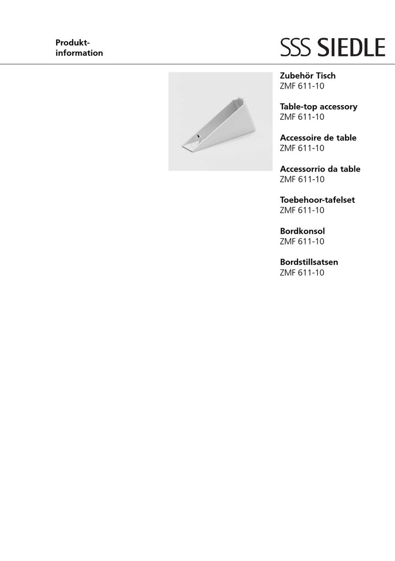
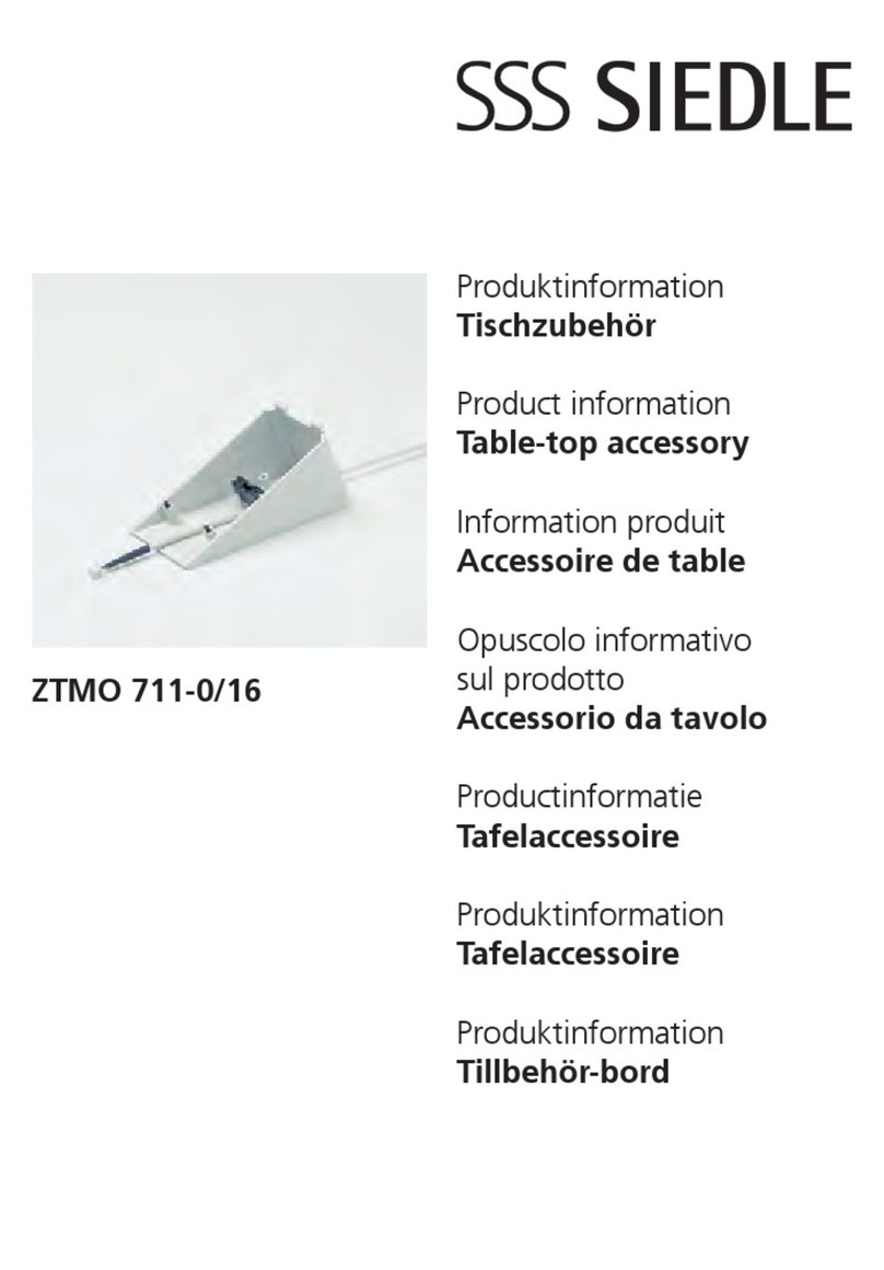
Das Zubehör Tisch ZT 711-01/12 mit
2 m langer Anschlusskabel, 12 poli-
gem Stecker und 12 pol. Anschluss-
dose, dient zur Umwandlung von
Wand- in Tischausführung des
HT 740-.. bei reiner Audio-Anwen-
dungen.
Für Anwendungen in Kombination
mit Video und Systemmonitoren
MOM/MOC 711-.. wird das Tisch-
zubehör ZT 711-01/16, sowie das
Zubehör ZTMO 711-0.. benötigt.
Montage
Die Anschlussdose für das
ZT 711-01/12..., unter Berücksichti-
gung der 2 m langen Anschlusska-
bel und dem Standort des System-
telefons, AP oder UP montieren.
1Öffnen des Systemtelefones durch
leichten Druck. Die Anschlussdrähte
des ZT... durch die Kabeleinführung
der Grundplatte einziehen.
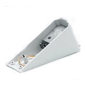
2Konsole nach Zeichnungen auf
dem Gehäuse-Unterteil befestigen
und die beiliegenden 2 Gummifüße
in die vorgesehenen Vertiefungen,
an der Unteren Schrägseite des
Telefons kleben.
3Die Anschlussdrähte nach An-
schlussschema anschließen.
Die Anschlussleitungen 9-12 können
beliebig für zusätzliche Funktionen,
bzw. Beschaltung von Eingängen,
bzw. Ausgängen benutzt werden.
4(Ohne Abbildung)
Anschlussklemmen, die im Außen-
schaltplan nicht aufgeführt sind,
bleiben unberücksichtigt. Freie bzw.
nicht benötigte Adern bitte in der
Konsole deponieren.
5(Ohne Abbildung) Gehäuse-
Oberteil wieder anbringen und
zusätzlich beiliegende zwei
Schraube (wie in Bild 2 dargestellt)
in das Gehäuse eindrehen:
Application
For pure audio applications, the
ZT 711-01/12 table-top accessory
with its flexible cord (2 m long),
12-pin connector, and 12-pole con-
necting box, accomplishes the con-
version from the wall into the table-
top design of the HT 740-.. internal
telephone.
When employing this unit in combi-
nation with the MOM/MOC 711-..
video and system monitors, the
ZT 711-01/16 table-top accessory
and the ZTMO 711-0.. accessory will
be required as well.
Installation
Flush or surface mount the connec-
ting socket for the ZT 711-01/12...,
taking into account the 2, metre-
long connecting cord of the system
telephone.
1Open the system telephone by
applying light pressure. Pull the
connection wires of the ZT.. through
the cable gland oft he base plate.
2Attach the brackets to the bottom
half of housing as shown and glue
the 2 enclosed rubber feet in the
corresponding holes in the sloped
surface of the bottom of the
telephone.
3Connect the connecting wires in
accorqance with the terminal dia-
gram.
As desired, the connecting wires 9
to 12 can be used for additional
functions, or the wiring of inputs
and/or outputs as well.
4(Not shown)
Terminals not listed in the wiring
diagram are not taken into account.
Isolate any free or unrequired wires
and deposit these in the bracket.
5(Not shown)
Reposition the housing superstructu-
re and screw the additionally enclo-
sed second screw into the housing
(as illustrated in Fig. 2).
Deutsch
Installation
English
Installation


