manuals.online logo
Brands
  1. Home
  2. •
  3. Brands
  4. •
  5. Steelcase
  6. •
  7. Indoor Furnishing
  8. •
  9. Steelcase Pathways User manual

Steelcase Pathways User manual

Page 1 of 14
939500174 Rev B
Pathways®Technology Wall - Floor to Ceiling,
Junctions and Trims
®
If you have a problem, question, or request, call
your local dealer, or Steelcase Line 1 at
888.STEELCASE (888.783.3522)
for immediate action by people who want to help you.
(Outside the U.S.A., Canada, Mexico, Puerto Rico,
and the U.S. Virgin Islands, call: 1.616.247.2500)
Or visit our website: www.steelcase.com
©2004 Steelcase Inc.
Grand Rapids, MI 49501
U.S.A.
Printed in U.S.A.
#2 PHILLIPS
3/16" HEX x 2" LONG DRIVE
BALL DRIVE
3" LONG
2" LONG
3/16" HEX x 3" LONG
Table of Contents
Page
2 Components
3 Notes
4 L-Junction, Full Height
5 T-Junction, Full Height
6 X-Junction, Full Height
7 Y-Junction, Full Height
8 V-Junction, Full Height
9 End of Run Trim, Full Height
10 End of Run Trim, Change of Height
11 T-Junction, Change of Height
12 L-Junction, Change of Height
13 V-Junction, Change of Height
14 Light Seals
Topic
Page 2 of 14
939500174 Rev B
1
2
5
Junction
Bracket
Top Plate
Assembly
L, T, X
3
4
Top Block
Assembly
L, T, X
15 1/4-20 x 1"
Screw
16 5/16-18 x 1"
Bolt
Bottom Block
Assembly
L, T, X
17 #8-18 x .360"
Pan Head
Screw
Components
Y, V
6Y, V
7
8
Y, V
EOR Clip
9EOR
Trim
L-Trim
no cap
T-Trim
no cap
V-Trim
no cap
Light Seal Light Seal
L, T & X Y & V
18 Aligner Bracket 19 Horizontal COH
Alignment Clip
20 21
10 11 12 13 14
or
Vertical Aligner
Bracket
Vertical Aligner
Junction Trim
Bracket
Page 3 of 14
939500174 Rev B
1. All floor to ceiling junctions and
trims logic is the same as partial
height, reference AD 939501684.
2. An additional trim holder (junction
block) is required above 84" to support
the trim, and if the application allows,
the junction block should be supported
by two (2) junction brackets.
3. Junction blocks are required at 66"
and 84" for all floor to ceiling
configurations.
4. When junction style calls for a
change of height T-trim or L-trim,
insert the horizontal aligner bracket
into the bottom end of trim. Install trim
and be sure to seat aligner down into
frame.
HORIZONTAL
ALIGNER
BRACKET
END TRIM
19
1
15
3 6
or
15
16
84"
Page 4 of 14
939500174 Rev B
L-Junction
Style No. C120LJ
1. Once the transom structure and
skin assembly is complete, measure
the distance from the floor to the
ceiling track.
2. Cut the L-trim 7/8" longer than the
dimension found in step 1.
3. Snap the L-trim on to the trim
holders, putting the cut end inside the
ceiling track.
Note: The transom trim holder can be
mounted above or below the factory-
provided location by using the junction
bracket as a template and drilling
two (2) 9/64" diameter pilot holes.
Tip: Position the transom trim holder
with item 15 to the best support the
trim. 10
1
1
2
1
1.
7/8"
84"
66"
4
3
3
3
Page 5 of 14
939500174 Rev B
T-Junction
Style No. C120TJ
1. Once the transom structure and
skin assembly is complete, measure
the distance from the floor to the
ceiling track.
2. Cut the T-trim 7/8" longer than the
dimension found in step 1.
3. Snap the L-trim on to the trim
holders, putting the cut end inside the
ceiling track.
Note: The transom trim holder can be
mounted above or below the factory-
provided location by using the junction
bracket as a template and drilling two
(2) 9/64" diameter pilot holes.
Tip: Position the transom trim holder
with item 15 to the best support the
trim.
11
1
1
2
1
1
1
2
1
4
3
3
3
1.
7/8"
84"
66"
Page 6 of 14
939500174 Rev B
X-Junction
Style No. C120XJ
1
1
2
1
1
1
2
1
1
1
2
1
4
3
3
3
84"
66"
Page 7 of 14
939500174 Rev B
Y-Junction
Style No. C120YJ
1
1
5
1
1
1
5
1
84"
66"
7
6
6
6
Page 8 of 14
939500174 Rev B
V-Junction
Style No. C120VJ
1. Once the transom structure and
skin assembly is complete, measure
the distance from the floor to the
ceiling track.
2. Cut the V-trim 7/8" longer than the
dimension found in step 1.
3. Snap the V-trim on to the trim
holders, putting the cut end inside the
ceiling track.
Note: The transom trim holder can be
mounted above or below the factory-
provided location by using the junction
bracket as a template and drilling
two (2) 9/64" diameter pilot holes.
Tip: Position the transom trim holder
with item 15 to the best support the
trim.
1
1
5
1
1.
7/8"
84"
66"
7
6
6
6
Page 9 of 14
939500174 Rev B
End of Run Trim
Style No. C120ERT
1. Once the transom structure and
skin assembly is complete, measure
the distance from the floor to the
ceiling track.
2. Cut the End of Run trim 5/8"
longer than the dimension found in
step 1.
3. Stand the trim adjaqcent to the
end of the panel and mark the clip
locations on the back side.
4. Slide the clips on to the trim from
the end to the proper position.
5. Snap the trim on to the frame,
putting the cut end inside the ceiling
track.
Note: Position the clips to best
support the trim based on the available
9
8
8
8
8
1.
5/8"
84"
66"
Page 10 of 14
939500174 Rev B
Change of Height Trim
Style No. C78CCT
1. Once the transom structure and
skin assembly is complete, measure
the distance from the top cap to the
ceiling track.
2. Cut the End of Run trim 5/8" longer
than the dimension found in step 1.
3. Stand the trim adjacent to the end
of the panel and mark the clip locations
on the back side.
4. Slide the clips on to the trim from
the end to the proper position.
5. Snap the trim on to the frame,
putting the cut end inside the ceiling
track.
Note: Position the clips to best support
the trim based on the available clip
locations.
1.
5/8"
84"
66"
9
8
8
8
Page 11 of 14
939500174 Rev B
T-Junction trim
Change of Height Trim
Style No. C78CTSJ
1. Once the transom structure and
skin assembly is complete, measure
the distance from the frame top to the
ceiling track.
2. Cut the T-trim 7/8" longer than the
dimension found in step 1.
3. Measure the distance from the
frame top to the top of the trim holder
above.
4. Secure the aligner bracket from
the bottom (uncut end) of the T-trim
1/16" greater than the dimension
found in step 3.
5. Snap the T-trim on to the trim
holders, putting the cut end inside the
ceiling track.
Note: The transom trim holder can be
mounted above or below the factory-
provided location by using the junction
bracket as a template and drilling two
(2) 9/64" diameter pilot holes.
Tip: Position the transom trim holder
with item 15 to the best support the
trim.
1.
7/8"
1/16"
84"
66"
11
19
3
3
20
17
3.
1
2
1
14
2
13
TOP VIEW
TOP VIEW
Page 12 of 14
939500174 Rev B
Style No. C78CLSJ
1. Once the transom
structure and skin assembly
is complete, measure the
distance from the frame top
to the ceiling track.
2. Cut the L-trim 7/8"
longer than the dimension
found in step 1.
3. Measure the distance
from the floor to the frame
top.

4. Cut the T-trim 1/16" 
shorter than the dimension
found in step 3.
5. Secure the aligner
bracket between the L and T
trim, putting the cut ends of
the trims at the floor and the
ceiling.
6. Snap the trim on to the
trim holders.
Note: The transom trim
holder can be mounted
above or below the factory-
provided location by using
the junction bracket as a
template and drilling two (2)
9/64" diameter pilot holes.
Tip: Position the transom
trim holder with item 15 to
the best support the trim.
1.
3.
7/8"
84"
66"
11
17
18
3
1
23
L-Junction trim
Change of Height Trim
3
1 2
TOP VIEW
4
1 1
TOP VIEW
Style No. C78CVSJ
1. Once the transom
structure and skin assembly is
complete, measure the
distance from the frame top to
the ceiling track.
2. Cut the V-trim 7/8" longer
than the dimension found in
step 1.
3. Measure the distance
from the frame top to the top
of the trim holder above.
4. Secure the aligner bracket
from the bottom uncut end of
the V-trim 1/16" greater than
the dimension found in step 3.
5. Snap the V-trim on to
the trim holders, putting the
cut end inside the ceiling
track.
Note: The transom trim
holder can be mounted
above or below the factory-
provided location by using
the junction bracket as a
template and drilling two (2)
9/64" diameter pilot holes.
Tip: Position the transom
trim holder with item 15 to
the best support the trim.
V-Junction trim
Change of Height Trim
1.
3.
7/8"
1/16"
84"
66"
1
1
1
5
6
6
6
21 17
7
1
5
12
Page 13 of 14
939500174 Rev B
Page 14 of 14
939500174 Rev B
Light Seals
1. Install all partial height light
seals before the transom stackers
are assembled, reference
assembly instruction 939501684.
2. Cut the light seal to length for
the transom area, putting a 45o
bevel on the lower end.
3. Install the light seal in a similar
manner as partial height, tucking
the bevelled end behind the partial
height seal.
Tip: Ceiling tiles may be removed
to aid the assembly of the transom
light seals.
45o
45o
13 14
or

Other manuals for Pathways

1

Other Steelcase Indoor Furnishing manuals

Steelcase QiVi User manual

Steelcase

Steelcase QiVi User manual

Steelcase Secant Pedestal User manual

Steelcase

Steelcase Secant Pedestal User manual

Steelcase Convene Firmware update

Steelcase

Steelcase Convene Firmware update

Steelcase Collaborative User manual

Steelcase

Steelcase Collaborative User manual

Steelcase migration User manual

Steelcase

Steelcase migration User manual

Steelcase Flex collection User manual

Steelcase

Steelcase Flex collection User manual

Steelcase Elective Elements Leg Base Tower User manual

Steelcase

Steelcase Elective Elements Leg Base Tower User manual

Steelcase Montage Wood Selections Firmware update

Steelcase

Steelcase Montage Wood Selections Firmware update

Steelcase Avenir Series User manual

Steelcase

Steelcase Avenir Series User manual

Steelcase UPV Series User manual

Steelcase

Steelcase UPV Series User manual

Steelcase Executive Elective Elements Table Desk Firmware update

Steelcase

Steelcase Executive Elective Elements Table Desk Firmware update

Steelcase FitWork 7 Series User manual

Steelcase

Steelcase FitWork 7 Series User manual

Steelcase Vertical Processor Sling CPRSLFO User manual

Steelcase

Steelcase Vertical Processor Sling CPRSLFO User manual

Steelcase Series 1 User manual

Steelcase

Steelcase Series 1 User manual

Steelcase TalkTime User manual

Steelcase

Steelcase TalkTime User manual

Steelcase Empath User manual

Steelcase

Steelcase Empath User manual

Steelcase Groupwork Flip-Top Table Use and care manual
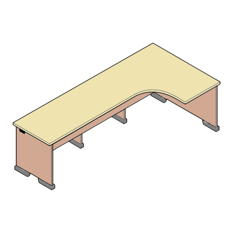
Steelcase

Steelcase Groupwork Flip-Top Table Use and care manual

Steelcase c:scape User manual

Steelcase

Steelcase c:scape User manual

Steelcase Criterion 453 Series Operating and safety instructions
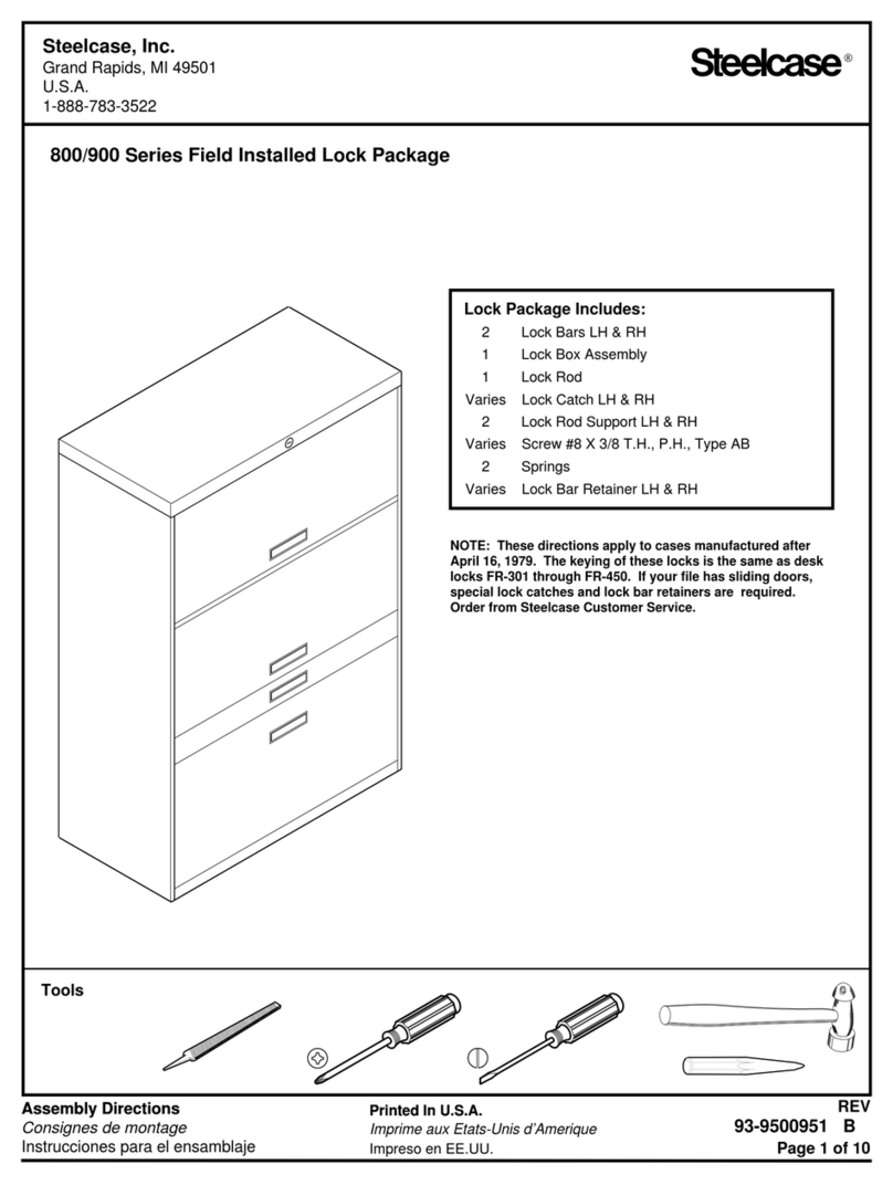
Steelcase

Steelcase Criterion 453 Series Operating and safety instructions

Steelcase Lumbar 1 Series User manual

Steelcase

Steelcase Lumbar 1 Series User manual

Steelcase Empath Reference guide

Steelcase

Steelcase Empath Reference guide

Steelcase Ology Rectangular Desk User manual

Steelcase

Steelcase Ology Rectangular Desk User manual

Steelcase migration User manual

Steelcase

Steelcase migration User manual

Steelcase Solo Sit-to-Stand Desk User manual

Steelcase

Steelcase Solo Sit-to-Stand Desk User manual

Popular Indoor Furnishing manuals by other brands

Mocka Sadie Bench Seat Assembly instructions

Mocka

Mocka Sadie Bench Seat Assembly instructions

Norbord CSS791 ASSEMBLEY GUIDE

Norbord

Norbord CSS791 ASSEMBLEY GUIDE

Regency Kobe MKTRCT4824 Assembly and installation

Regency

Regency Kobe MKTRCT4824 Assembly and installation

Costway HV10180 user manual

Costway

Costway HV10180 user manual

Costway JZ10069CF Instruction booklet

Costway

Costway JZ10069CF Instruction booklet

Furniture Solutions Zica manual

Furniture Solutions

Furniture Solutions Zica manual

George & Willy FELT BOARD manual

George & Willy

George & Willy FELT BOARD manual

MotionGrey Ergo 2 Series Assembly instruction

MotionGrey

MotionGrey Ergo 2 Series Assembly instruction

The Land of Nod Wrightwood Twin-over-Twin Bunk Bed Assembly instructions

The Land of Nod

The Land of Nod Wrightwood Twin-over-Twin Bunk Bed Assembly instructions

EFG 039170 Assembly instruction

EFG

EFG 039170 Assembly instruction

BROSA OSTRO Assembly guide

BROSA

BROSA OSTRO Assembly guide

modway MOD-5804 quick start guide

modway

modway MOD-5804 quick start guide

modway EEI-4656 manual

modway

modway EEI-4656 manual

Next 569477 Assembly instructions

Next

Next 569477 Assembly instructions

Next Level Racing PRO GAMING CHAIR instruction manual

Next Level Racing

Next Level Racing PRO GAMING CHAIR instruction manual

VERTBAUDET 70501-1631 manual

VERTBAUDET

VERTBAUDET 70501-1631 manual

Z2 Magara MGAK236 Assembling Instruction

Z2

Z2 Magara MGAK236 Assembling Instruction

Liat Panther installation instructions

Liat

Liat Panther installation instructions

manuals.online logo
manuals.online logoBrands
  • About & Mission
  • Contact us
  • Privacy Policy
  • Terms and Conditions

Copyright 2025 Manuals.Online. All Rights Reserved.