Steren CCTV-500 User manual

Product / Producto:
Model / Modelo:
Brand / Marca:
Wireless CCTV With
Monitor / Circuito
cerrado de TV
inalámbrico Con
Monitor
CCTV-500
STEREN
CONDICIONES
1. Para hacer efectiva esta garantía se requiere: La presentación de ésta póliza y del producto, en el lugar en donde fue adquirido o en ELECTRONICA STEREN S.A. DE C.V.
2. ELECTRONICA STEREN S.A. DE C.V. se compromete a reparar el producto en caso de estar defectuoso sin ningún cargo al consumidor.
3. El tiempo de reparación en ningún caso será mayor a 30 días contados a partit de la recepción del producto en cualquiera de los sitios en donde pueda hacerse efectuva la
garantía.
4. El lugar donde puede adquirir ártes, componentes, consumibles y accesorios, así como hacer válida esta garantía es: En cualquiera de las direcciones arriba mencionadas.
ESTA GARANTIA NO ES VALIDA EN LOS SIGUIENTES CASOS
1. Cuando el producto ha sido utilizado en condiciones distintas a las normales.
2. Cuando el producto no ha sido operado de acuerdo con el instructivo de uso.
3. Cuando el producto ha sido alterado o reparado por personas no autorizadas por ELECTRONICA STEREN S.A. DE C.V.
Nota: El consumidor podrá solicitar que se haga efectiva la garantía ante la propia casa comercial, donde adquirió el producto. Si la presente garantía se extraviara, el
consumidor puede recurrir a su proovedor para que le expida otra póliza de garantía, previa presentación de la nota de compra o factura respectiva.
DATOS DEL DISTRIBUIDOR
DISTRIBUTION / NOMBRE /DISTRIBUIDOR:
ADDRESS / DOMICILIO:
PRODUCT / PRODUCTO: BRAND / MARCA:
MODEL / MODELO: SERIAL NUMBER / No. DE SERIE:
DATE OF DELIVERY / FECHA DE ENTREGA:
Call Center / Centro de Atención a Clientes
del Interior 01 800 500 9000
Mexico City / Cd. de México: 53 54 22 90
This Steren product is warranted under
normal usage against defects in
workmanship and materials to the original
purchaser for one year from the date of
purchase.
Garantiza este producto por el término de
un año en todas sus partes y mano de
obra contra cualquier defecto de fabricación
y funcionamiento, a partir de la fecha de
entrega.
Warranty
CONDITIONS:
1. This warranty card with all the required information, the invoice or purchase ticket, the product box or package, and the product, must be presented with the product
when warranty service is required.
2. If the product stills on the warranty time, the company will repair it free of charge even the transportation charges.
3. The repairing time will not exceed 30 natural days, from the day the claim was received.
4. Steren sells parts, components, consumables and accessories to customer, as well as warranty service, at any of the following addresses:
THIS WARRANTY IS VOID ON THE NEXT CASES:
If the product has been damage by an accident, acts of God, mishandling, leaky batteries, failure to follow enclosed instructions, improper repair by unauthorized
personal, improper safe keeping or otherwise.
Notes:
a) The customer can also claim the warranty service on the purchase establishment.
b) If you lose the warranty card, we can reissue it just showing the invoice or purchase ticket.
Póliza de Garantía

STEREN recomienda que antes de usar su nueva unidad lea este
manual de instrucciones para prevenir cualquier mal funcionamiento.
Solo siga estas instrucciones y fácilmente podrá utilizar su nuevo
Circuito Cerrado de TV Blanco y Negro.
RECOMENDACIONES IMPORTANTES DE SEGURIDAD.
COMO USAR EL CCTV-500 PARA OPTIMO DESEMPEÑO
STEREN recommends before use the Wireless Surveillance
System to read this instruction manual to prevent any damage.
Just follow these instructions and easily you will be using your new
Wireless Surveillance System.
SAFETY PRECAUTIONS
HOW TO USE CCTV-500 FOR OPTIMAL PERFORMANCE
Para prevenir el riesgo de incendio o choque eléctrico, no
exponga este producto a la lluvia o humedad. No se use cerca
de la bañera, el lavabo, el fregadero, o el lavadero. No se use en
un sótano húmedo o cerca de una piscina.
Con el fin de prevenir choques eléctricos, no abra la cubierta de
este producto.
Alimente este producto usando solamente los adaptadores incluidos.
No sobrecargue las salidas de corriente eléctrica o extensiones
ya que esto puede traer como consecuencia incendios o
choques eléctricos.
NOTA: Este equipo ha sido probado y cumple con las
especificaciones para un dispositivo digital de clase B, de
conformidad con el apartado 15 de las reglas de la FCC. Esos
límites han sido diseñados para proteger contra interferencias
dañinas en una instalación residencial. Este equipo genera, usa
y es capaz de emitir energía de radio frecuencia, si no se instala
o se usa de acuerdo a las instrucciones, puede causar
interferencia que dañe las radio comunicaciones. Sin embargo,
no hay garantía de que la interferencia no va a ocurrir en alguna
instalación en particular. Si el equipo causa interferencia a la
recepción de radio y televisión (se puede identificar apagando y
encendiendo el equipo), puede corregir estas interferencias con
alguno de los siguientes pasos:
Reoriente o reubique la antena receptora.
Aumente la separación que hay entre el equipo que recibe la
interferencia y el receptor.
Conecte el equipo que recibe la interferencia a un enchufe o un
circuito diferente de aquel en el que se encuentra el receptor.
Consulte a la tienda donde adquirió su sistema o a un técnico de
TV para obtener ayuda.
-
-
-
-
-
-
-
-
To prevent fire or shock hazard, do not expose this product to
rain or moisture. Do not use near a bathtub, washbowl, sink
or laundry tub. Do not use in a wet basement or around a
swimming pool.
To avoid electrical shock, do not open the case of this
product.
Operate this product using only the power supply included.
Do not overload electrical outlets or extension cord, it may
result in fire or electric shock
NOTE: This system has been tested and found to comply with
the limits for Class B digital device, pursuant to part 15 of the
FCC rules. These limits are designed to provide reasonable
protection against harmful interference in a residential
installation. This system generates, uses and can radiate
radio frequency energy. If it is not installed and used in
accordance with the instructions, may cause harmful
interference to radio or TV reception, which can be
determined by turning the equipment off and on, the user is
encouraged to try to correct the interference by one or more
of the following measures:
Reorient or relocate the receiving antenna.
Increase the separation between the equipment and receiver
Connect the system to a different circuit from the one the
receiver is connected
Consult the dealer or a radio/TV technician for help.
-
-
-
-
-
-
-
-
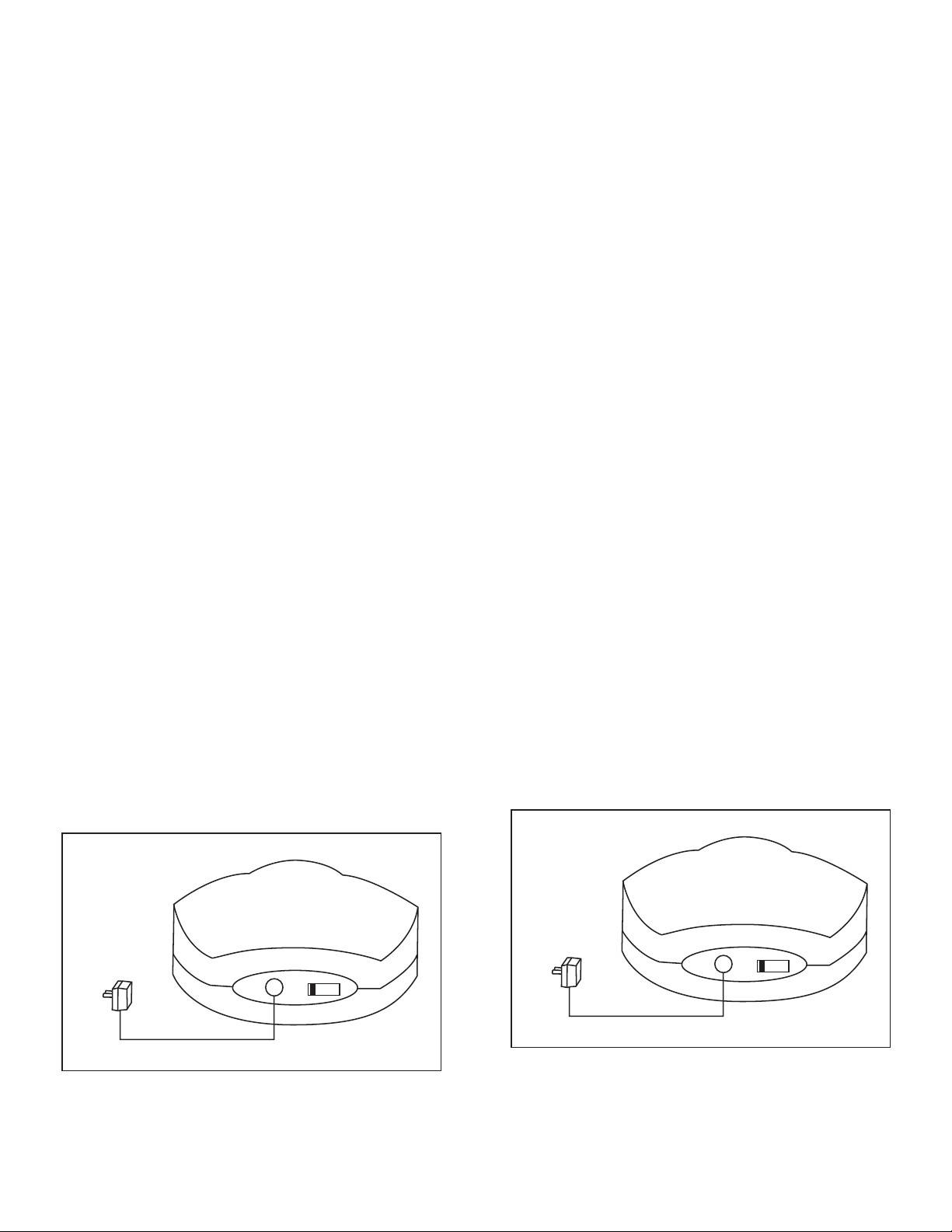
It should be placed on a flat stable surface.
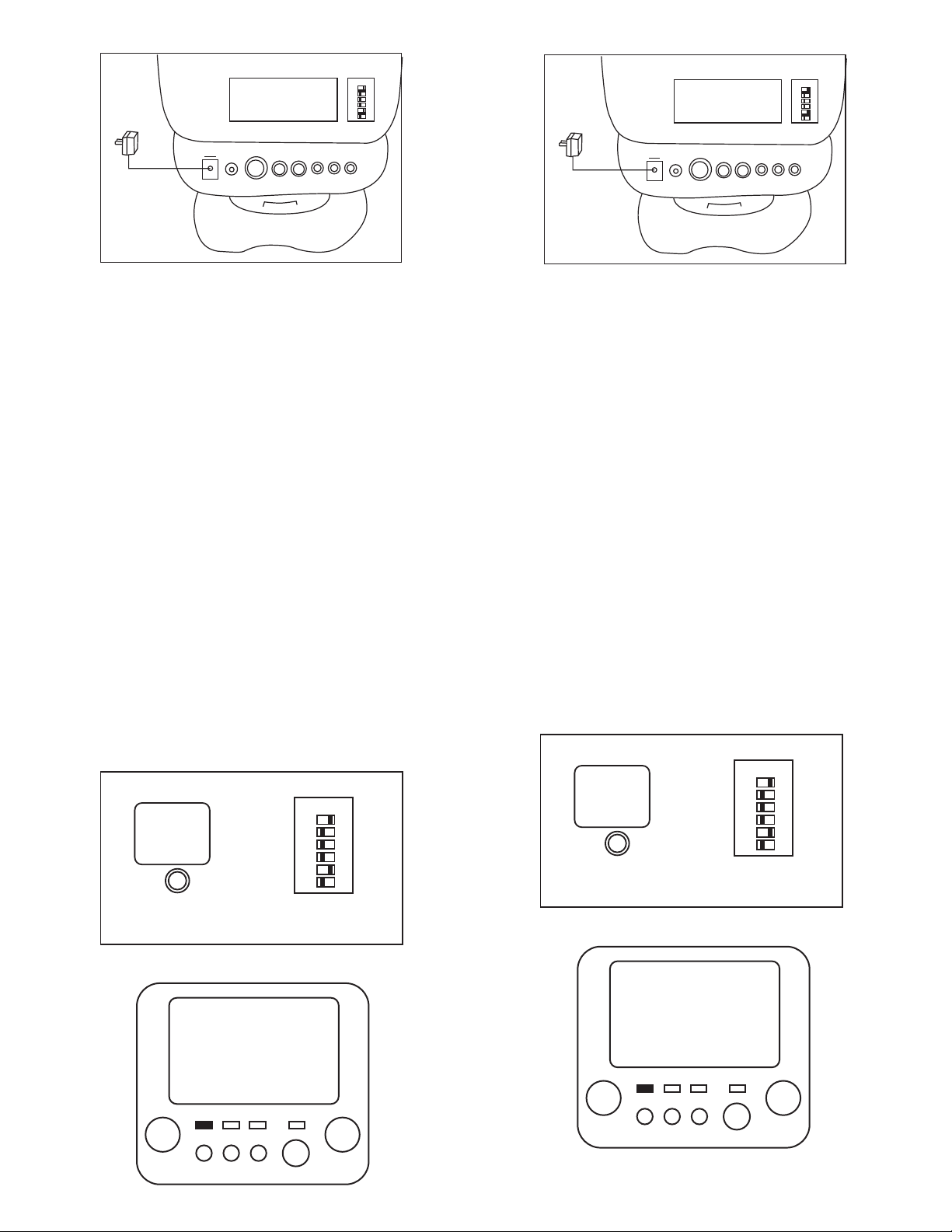
For maximum operating range, try to minimize the number of
obstacles (TV, other electronics, large steel structures)
between the transmitter and the receiver.
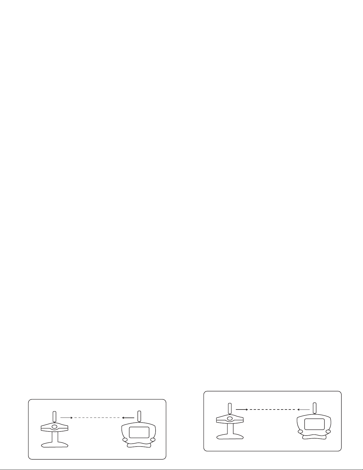
It broadcast high-quality audio and video, using directional
antennas which must be oriented in certain configurations for
best results. The antennas have been designed to pivot and
rotate in almost any direction. In most situations, the flat face of
the antennas on transmitter and receiver should be facing and
perpendicular (at a right angle) to an imaginary line drawn
between two units. Examples are shown forward. If the
transmitter and receiver are less than 10 feet apart, keep the
antennas flat.
Avoid pointing the camera directly into light or sunlight. You
may not have a proper image.
To receive optimum image performance, always make sure
lenses are clean.
This camera is not waterproof. Do not use in wet or high
humidity environments, as this can cause camera damage or
electrical shock.
1.
2.
3.
4.
5.
6.
El receptor del CCTV-500 deberá ser colocado en una superficie
plana y estable con el fin de prevenir daño debido a caídas.
Para máximo rango de operación, trate de minimizar la
cantidad de obstáculos (Como paredes, grandes estructuras,
televisiones u otros equipos electrónicos)
Este equipo difunde audio y video de alta calidad usando
antenas direccionales que deben ser usadas en cierta
configuración para mejores resultados, las antenas han sido
diseñadas para girar sobre un eje y apuntar casi en cualquier
dirección. En la mayoría de las aplicaciones la cara plana de la
antena tanto en el transmisor como en el receptor deberán estar
apuntando una a la otra y estar en una posición perpendicular
(Es decir en ángulo recto) a una línea imaginaria dibujada entre
las dos unidades, más adelante observará tres ejemplos. Si el
transmisor y el receptor se encuentran a menos de 3 metros de
distancia conserve las antenas en su posición abatida.
Evite apuntar la cámara hacia lugares muy iluminados o con
luz solar, esto podría no darle buenas imágenes.
Para recibir imágenes óptimas, siempre asegúrese que el lente
de la cámara se encuentra limpio.
La cámara no es resistente al agua, no la utilice en lugares
mojados o con demasiada humedad, esto puede causar daños
a la cámara o choques eléctricos.
1.
2.
3.
4.
5.
6.
TRANSMISOR
(Vista frontal)
LADO PLANO LADO PLANO
ANTENA
AUDIO/VIDEO ANTENA
AUDIO/VIDEO
RECEPTOR
(Vista frontal)
TRANSMITER
(Front view)
FLAT SIDE
AUDIO/VIDEO
ANTENNA
FLAT SIDE
AUDIO/VIDEO
ANTENNA
RECIVER
(Front view)

CAMARA INALAMBRICA
1. Switch de encendido y apagado.
Enciende y apaga la cámara.
2. Ajuste de enfoque.
Ajusta el lente para obtener imágenes claras.
3. Lente
Sensor de imagen CMOS de 1/3”
4. Luz indicadora de encendido
Indica que la cámara está encendida o apagada.
5. Micrófono
Micrófono de alta sensibilidad omnidireccional (recibe señal 360°),
sonido estéreo.
6. Luminarias infrarrojas
Estos dispositivos emitirán luz infrarroja para iluminar durante la
noche o zonas muy obscuras.
7. Antena direccional de 2,4 GHz
Envía las señales de audio y video.
8. Entrada de alimentación
Aquí se conecta el adaptador de voltaje incluido.
9. Selector de Canal
Use este selector para óptima recepción. El canal seleccionado
debe ser el mismo en el transmisor y en el receptor.
RECEPTOR INALAMBRICO
WIRELESS CAMERA
1. Power ON/OFF switch
Switch for the power on/off
2. Lens adjustor
Adjust lens for optimal image
3. Lens
1/3 CMOS Image sensor
4. Power indicator light
Indicate the power is working or not.
5. Microphone
High sensitivity condenser microphone with stereo sound
6. IR emitting tube
Help work at night and dark place
7. Directional 2,4 GHz antenna
Sends audio and video signals.
8. DC IN
Plug the 10 volt adaptor
9. Channel selector
Use to find optimal reception. Must select same channel on both
transmitter and receiver
WIRELESS RECEIVER
TRANSMISOR
(Vista frontal)
LADO PLANO
ANTENA
AUDIO/VIDEO LADO PLANO
ANTENA
AUDIO/VIDEO
RECEPTOR
(Vista frontal)
TRANMISOR
(Vista frontal)
LADOPLANO
ANTENA
AUDIO/VIDEO
LADOPLANO
ANTENA
AUDIO/VIDEO
RECEPTOR
(Vista frontal)
TRANSMITER
(Front view)
FLAT SIDE
AUDIO/VIDEO
ANTENNA FLAT SIDE
AUDIO/VIDEO
ANTENNA
RECIVER
(Front view)
TRANSMITER
(Front view)
FLATSIDE
AUDIO/VIDEO
ANTENNA
FLATSIDE
AUDIO/VIDEO
ANTENNA
RECIVER
(Front view)
6
45
3
2
1
7
9
86
45
3
2
1
7
9
8
1
2
3
4
2S
4S
ON
PHONE
DC EXT.ANT AUDIO VIDEO CONT BRIGHT V. HOLD
+-
6
10
9
5
43217
8
11
12 13 14 15 16
17
18
19
1
2
3
4
2S
4S
ON
PHONE
DC EXT.ANT AUDIO VIDEO CONT BRIGHT V. HOLD
+-
6
10
9
5
43217
8
11
12 13 14 15 16
17
18
19

1. Switch de encendido y apagado.
Botón para encender o apagar el monitor.
2. Botón de pausa.
Detiene la exploración de los canales fijándolo en uno (de las 4
cámaras disponibles). Se detiene en el canal seleccionado.
3. Botón de selección de canal de televisión (CH).
Selecciona la banda de televisión (VL/VH/UHF).
4. TV / monitor switch.
Permite recibir señales de televisión o entrar al modo de monitor.
5. Control de volumen
Ajusta el volumen.
6. Luces indicadoras de banda (VL/VH/UHF).
Indica la banda en la cual está trabajando el televisor.
7. Luz indicadora de energía.
Indica que el equipo está encendido.
8. Control de sintonía fina.
Ajústelo para tener una mejor recepción de televisión.
9. Antena de televisión.
Ayuda a recibir una imagen óptima de televisión.
10. Antena direccional de 2,4 GHz
Recibe y envía señales de audio y video.
11. Entrada de corriente.
Conecte el plug del adaptador
12. Jack para audífonos.
Sirve para conectar un Audífono.
13. Conector para antena externa.
Conecte una antena para obtener mejor recepción.
14. Jack de salida de audio.
Conector RCA de audio para conexión con cables.
15. Jack de salida de video.
Conector RCA de video para conexión con cables.
16. Contraste.
Ajústelo para tener el contraste deseado
17. Brillo
Ajústelo para tener el brillo deseado
18. V-HOLD
Fija la imagen para darle estabilidad cuando esta es inestable.
19. Switches de selección
Seleccionan el canal para las cámaras inalámbricas y ajustan el
tiempo de retardo.
Este sistema inalámbrico de circuito cerrado puede también ser
utilizado con tres cámaras adicionales (no incluidas). Modelo CCTV-550
CAMARA INALAMBRICA
1. Ubique la cámara en la zona que desea observar.
2. Conecte el convertidor de tensión a la corriente y este a su vez a
la entrada de alimentación ubicada en la parte trasera de la
cámara. El LED indicador de encendido, ubicado en la parte frontal
de la cámara, se encenderá.
1. Power ON/OFF switch
Switch for the power ON/OFF
2. Pause button
Lock a certain channel
3. TV channel selection button
TV channel select and receive ????
4. TV / monitor switch.
TV receive and monitoring status switch
5. Volume control
Adjust the volume to suitable degree
6. TV channel indicator lights
Indicates the working TV channel
7. Power indicator light
Indicates power is ON
8. Fine tuning control
Adjust to get the best TV reception
9. TV antenna
Helps to receive the optimal image of TV program
10. Directional 2.4 GHZ antenna
Sends audio and video signals
11. DC IN
Plug in the 12 volt adaptor (supplied) power source.
12. Headphone Jack
Connect headset
13. Ext. antenna jack
Conecte un antena para obtener mejor recepciÛn.
14. Audio out RCA jack
RCA audio out jack for wire mode operation
15. Video out RCA jack
Video out jack for wire mode operation
16. Contrast
Adjust it to get the best gradation
17. Brightness
Adjust it to get better brightness
18. V-HOLD
Fix frame to stable image
19. Selector box
Channel selection and set the dwell time
This wireless surveillance System can also be set to use 3 additional
cameras model CCTV-550 (not included) with the monitor.
WIRELESS CAMERA
1. Place the camera where you want to observe
2. Connect the supplied 300mA adaptor to DC IN jack on the rear of
the camera. Plug it into AC power outlet. The red LED (Power
indicator light) on the front of the camera will flash to indicate unit is
ON
DC 8V CH 1 2 3 4
ADAPTOR AC
DC 8V 300mA DC 8V CH 1 2 3 4
DC 8V 300mA
AC ADAPTOR

RECEPTOR INALAMBRICO
1. Ubique el receptor en el lugar donde desee ver la imagen
monitoreada.
2. Oriente la antena del receptor hacia la antena de la cámara de
forma que estén apuntando una a la otra de forma paralela.
3. Conecte el convertidor de tensión, incluido, a la corriente y este a
su vez a la entrada de alimentación ubicada en la parte trasera del
receptor.
4. Encienda el receptor marcado como POWER. La luz indicadora
de encendido (LED rojo), ubicado en la parte frontal, indicara que
está encendido.
Como configurar el modo automático o manual
El sistema de circuito cerrado inalámbrico tiene un receptor flexible
de 4 canales con varias funciones integradas. Este puede operar
en el modo manual, de forma que los canales son cambiados
presionando el botón PAUSE ubicado en la parte frontal del
receptor.
Operación en el modo automático
Cuando se enciende el receptor automáticamente entra al modo
automático. El monitor automáticamente cambiarán entre los canales
(imágenes de las cámaras) y se detendrá en cada canal de acuerdo
al tiempo de retardo seleccionado.
Se puede seleccionar un canal a visualizar deslizando uno de los
switches (ubicados en la parte trasera del monitor) a la posición ON.
Operación en el modo manual
Presione el botón PAUSE, la imagen se detendrá y permanecerá
en ese canal. Si se presiona el botón PAUSE otra vez la imagen
cambiará al siguiente canal.
Si en los switches de atrás únicamente hay un canal en la posición
ON, entonces no habrá necesidad de presionar el botón PAUSE la
imagen se quedará automáticamente en el canal seleccionado.
OPERACION DEL RECEPTOR DE TELEVISION
WIRELESS RECEIVER
1. Place the wireless receiver unit where you want to watch the
observed image.
2. Set the right angle of the flat potted face of the antenna toward
the transmitter antenna
3. Connect the adaptor to the DC IN jack at the rear of the receiver
and plug it into AC outlet
4. Turn on the power switch. The red LED on the front of the
receiver will indicate the unit is ON.
How to set up automatic/manual switching mode
Your system is a flexible 4 channel receiver with many options built-
in. It may be operated in the manual mode with the channels being
changed by pressing the CH button on the front of the receiver
case.
Automatic mode operation
When you turn ON the receiver defaults to the automatic mode. The
monitor will switch instantly between channels (camera views) and
pause at each channel according to dwell time selected.
Manual mode operation
Press PAUSE button and the picture will stop and remain on that
channel. Press PAUSE button again to shift to next selected
channel.
If you only set one channel to ON position, then there is no need to
press the PAUSE button, the picture will stay automatically on the
selected channel.
TV RECEIVING OPERATION
1
2
3
4
2S
4S
ON
PHONE
DC EXT. ANT AUDIO VIDEO CONT BRIGHT V. HOLD
ADAPTADOR AC
DC 12V 1200mA
+-
1
2
3
4
2S
4S
ON
PHONE
DC EXT. ANT AUDIO VIDEO CONT BRIGHT V. HOLD
DC 12V 1200mA
AC ADAPTOR
+-
1
2
3
4
2S
4S
ON
Panel de Selección
BOTON DE PAUSA
Pantalla
1
2
3
4
2S
4S
ON
Selector Box
PAUSE BUTTON
Screen
SCREEN
VOL TUN
POWER
PAUSECHMON
TV
VL VH UHF
PANEL FRONTAL DEL RECEPTOR
SCREEN
VOL TUN
POWER
PAUSECHMON
TV
VL VH UHF
RECEIVER FRONT PANEL

Este receptor también funciona como un televisor ordinario.
Primero encienda el receptor, presione el botón TV/MON para
cambiar a la posición de televisión. Después presione el botón CH
para seleccionar la banda de televisión deseada VL, VH, o UHF.
Ajuste el control de sintonía hasta lograr una recepción correcta.
Ajuste también la antena hasta que tenga una recepción óptima de
la señal de televisión tanto en imagen como en sonido. Ajuste el
volumen hasta el valor deseado. De esta forma usted podrá
disfrutar de los canales de televisión.
OPERACION EN EL MODO DE MONITOREO
Asegúrese que el monitor esté encendido antes de usarse.
1. Oriente la antena del receptor hacia la antena de la cámara de
forma que estén apuntando una a la otra de forma paralela.
2. Cada lugar donde se coloque este sistema tiene diferente
recepción, los materiales utilizados para las construcciones como
ductos, acero, concreto, etc., crearán diferentes condiciones de
recepción. En algunos casos será necesario mover la orientación de
las antenas o la posición de la cámara o el receptor para tener la
mejor recepción.
3. Cuando el receptor esté trabajando, presione el botón TV/MON a la
posición MON, la unidad comenzará la auto búsqueda (asegúrese de
que al menos una de las cámaras esté encendida). Refiérase al
apartado “Como configurar el modo secuencial a automático o manual”.
MONITOREO CON VISUALIZACION EN UN TELEVISOR
1. Si usted tiene un televisor con entradas de audio y video conecte
un juego de cables RCA entre la salida de A/V del receptor y la
entrada A/V del televisor, asegúrese de que el conector amarillo
coincide con el conector amarillo, y el rojo con el rojo.
2. Asegúrese de que el receptor se encuentra apagado, conecte el
convertidor de tensión incluido, a la corriente y este a su vez a la
entrada de alimentación ubicada en la parte trasera del receptor. Use
únicamente el convertidor incluido.
3. Localice y oriente el receptor siguiendo los pasos descritos en la
sección “Como usar el CCTV-500 para óptimo desempeño”.
MONITOREO UN TELEVISOR Y UNA VIDEO CASETERA
Esta operación le permite grabar las señales de audio y video transmitidas
en su video casetera y además reproducirlas en su televisión.
1. Conecte un juego de cables de audio y video entre su receptor y
los jacks RCA marcados como LINE IN en su video casetera,
asegúrese de que el conector amarillo coincide con el conector
amarillo, el rojo con el rojo y el blanco con el blanco. Si la video
casetera solo tiene una entrada de audio, conecte el plug blanco RCA
en esta entrada.
2. Use un cable coaxial para conectar la salida de la video casetera a
la entrada de antena de la televisión.
3. Asegúrese de que el receptor se encuentra apagado, conecte el
convertidor de tensión incluido, a la corriente y este a su vez a la
entrada de alimentación ubicada en la parte trasera del receptor. Use
únicamente el convertidor incluido.
4. Localice y oriente el receptor siguiendo los pasos descritos en la
sección “Como usar el CCTV-500 para óptimo desempeño”.
This receiver also works as a regular TV. First turn ON the receiver,
press TV/MON button to TV status and press CH button to chose a
TV band (VL, VH, o UHF). Set the fine tuning control a TV program.
Set the antenna to suitable angle and direction to receive the
optimal image and sound. Set the volume to the desired level. Then
you can enjoy broadcast TV programs.
OBSERVATION RECEIVING OPERATION
Make sure monitor is turned on before use it.
1. The flat face of the antennas on the transmitter and receiver
should be facing one another to get the best picture and sound.
2. Each home or office has different reception. Different construction
products, such as foil insulation, heating ducts, steel studs, etc., will
create different conditions. It may be necessary to set the right
angle of the antenna or move the wireless camera and wireless
receiver to get the best reception
3. When the receiver is working, press TV/MON button to MON
status. The unit starts auto scanning (Make sure at least one
channel is turned on) refer to HOW TO SET UP
AUTOMATIC/MANUAL SWITCHING MODE
OBSERVATION RECEIVING OPERATION WITH TV
1. If your TV has audio/video (A/V) jacks, connect one set of A/V
cables (not included) to the TV´s A/V jacks and to the A/V jacks on
the receiver. Be sure plugs and jack match yellow to yellow, white to
white on both the TV and receiver
2. Plug one end of the power adaptor into the back of the receiver
and the other into AC outlet. Use only the adaptor included. Make
sure the POWER switch is OFF before plug it in the AC outlet.
3. Locate and orient the receiver according to the section of this
manual titled HOW TO USE YOUR CCTV-500 FOR OPTIMAL
PERFORMANCE
OBSERVATION RECEIVING OPERATION WITH TV & VCR
This setup enables you to record transmitted audio and video on
your remote VCR and also enjoy the picture and sound on a remote
TV.
1. Connect one set of A/V cables (not included) to A/V jacks of the
receiver and to the jacks on your VCR labeled LINE IN. Make sure
the yellow and white plugs match the yellow and white jacks on the
receiver and the VCR.
2. Use coaxial cable to connect the A/V jack on your VCR labeled
OUT and TV’s outdoor antenna jack.
3. Plug one end of the power adaptor into the back of the receiver
and the other into AC outlet. Use only the adaptor included. Make
sure the POWER switch is OFF before plug it in the AC outlet.
4. Locate and orient the receiver according to the section of this
manual titled HOW TO USE YOUR CCTV-500 FOR OPTIMAL
PERFORMANCE
PANEL POSTERIOR DEL RECEPTOR
PHONE
DC EXT. ANT AUDIO VIDEO CONT BRIGHT V. HOLD
+-
INPUT
AUDIO VIDEO
TV
CABLE A/V
SALIDA
A CORRIENTE
PHONE
DC EXT. ANT AUDIO VIDEO CONT BRIGHT V. HOLD
+-
INPUT
AUDIO VIDEO
TV
A/V CABLE
TO POWER
OUTLET
REAR RECEIVER PANEL
-Each VCR manufacturer use different method to record.
-Refer to VCR’s for specific instructions.
-Cada video casetera usa diferentes métodos para realizar la grabación.
-Refiérase al manual de su equipo para instrucciones específicas.

SOLUCION DE FALLAS
ESPECIFICACIONES
TROUBLE SHOOTING
SPECIFICATIONS
Problema
No hay energía
(No hay imagen
ni audio)
El convertidor de tensión
no se conectó
apropiadamente a la
corriente.
El convertidor de tensión
no se conectó
apropiadamente a la
corriente.
Recepción pobre. La orientación de la
antena no es la correcta,
no se ha seleccionado
el canal adecuado.
La orientación de la
antena no es la correcta.
Imagen demasiado
pobre, muy brillante
o demasiado oscura.
Ajuste los controles de
brillo y / o contraste en
el monitor o televisión.
Aumente un poco la
iluminación del área que
se está monitoreando.
La imagen no
permanece estable
y parece que sube
o baja.
Ajuste el control V-hold
(Vertical) en el monitor
o televisión
La imagen es más
pequeña que la
pantalla o el
volumen es débil
Es posible que el
voltaje de línea esté
demasiado bajo
Es posible que el
voltaje de línea esté
vvdemasiado bajo
La imagen
parpadea
El área que se encuentra
monitoreando está
demasiado iluminada.
Causa y solución
Receptor Cámara Problem
No power
(No picture/sound)
AC adaptor was not
plugged in the output
properly.
AC adaptor was not
plugged in the output
properly.
Poor reception Improper antenna
direction; improper
channel setting.
Improper antenna
direction.
Dim picture, picture
too bright, too dark.
Improper brightness
control setting on your
TV/Monitor.
Lighting source in the
field of view.
Picture rolls and
jumps scrambled
picture
Improper V-hold control
setting on your
TV/Monitor
Picture smaller than
screen or volume
weak.
AC house current
may be too low
AC house current
may be too low
Picture flicking Strong spotlight in the
field of view
Cause and remedies
Receiver Camera
RECEPTOR INALAMBRICO
Nivel de salida:
Dimensiones (14cm/5,5"):
Peso:
CAMARA INALAMBRICA
Nivel de salida:
Frecuencia:
Modulación:
Nivel de entrada de video:
Nivel de entrada de audio:
Impedancia de entrada de video:
Impedancia de entrada de audio:
Iluminación utilizable:
Dimensiones:
Peso:
COVERTIDORES DE TENSION ca / cc
Para la cámara
Entrada:
Salida:
Para el receptor
Entrada:
Salida:
1Vpp
183x210x201 mm
2,03 kg
1 Vpp
2,420 a 2,480 GHz
FM (Video y Audio)
1 Vpp
1 Vpp
75 ohms
600 ohms
1,4 Lux
140 x 120 x 120 mm
0,67 kg
120 V ~ 60Hz 5W
8V --- 400mA
120V ~ 60Hz 15W
12V --- 1 200mA
WIRELESS RECEIVER
Output level:
Sizes (5,5"/14cm):
Weigth:
WIRELESS CMOS CAMARA
Output level:
Operating frequency band:
Modulation:
Video input level:
Audio input level:
Video input impedance:
Audio input impedance:
Usable illumination:
Sizes:
Weight:
COVERTIDORES DE TENSION ca / cc
For the camera
Input:
Output:
For the receiver
Input:
Output:
1Vpp
183x210x201 mm
2,03 kgs
1 Vpp
2,420 a 2,480 GHz
FM (Video y Audio)
1 Vpp
1 Vpp
75 ohms
600 ohms
1,4 Lux
140 x 120 x 120 mm
0,67 kgs
120 V ~ 60Hz 5W
8V --- 400mA
120V ~ 60Hz 15W
12V --- 1 200mA
PANEL POSTERIOR DEL RECEPTOR
PHONE
DC EXT. ANT AUDIO VIDEO CONT BRIGHT V. HOLD
+-
INPUT
COAXIAL CABLE
TO POWER
OUTLET
IN
AUDIO VIDEO
OUT
TV
VCR
RECEIVER REAR PANEL
PHONE
DC EXT. ANT AUDIO VIDEO CONT BRIGHT V. HOLD
+-
INPUT
COAXIAL CABLE
TO POWER
OUTLET
IN
AUDIO VIDEO
OUT
TV
VCR
Entrada:8V --- 400mA
Entrada:8 V --- 1200 mA
Input:8 V --- 400mA
Input:8 V --- 1200mA
Table of contents
Other Steren Security System manuals

Steren
Steren CCTV-095 User manual

Steren
Steren ALA-010 User manual

Steren
Steren AUT-200 User manual

Steren
Steren ALA-170 User manual

Steren
Steren CCTV-2000 User manual

Steren
Steren ALA-110 User manual

Steren
Steren ALA-2000 User manual

Steren
Steren ALA-080 User manual

Steren
Steren ALA-100 User manual

Steren
Steren CCTV-2100 User manual