Thank you very much for using SUNX products.
Please read this Instruction Manual carefully and
thoroughly for the correct and optimum use of this
product. Kindly keep this manual in a convenient
place for quick reference.
CAUTIONS
2
٨
٨
٨
٨
٨
٨
Make sure to carry out wiring in the power sup-
ply off condition.
Take care that wrong wiring will damage the sensor.
Verify that the supply voltage variation is within
the rating.
If power is supplied from a commercial switching
regulator, ensure that the frame ground (F.G.)
terminal of the power supply is connected to an
actual ground.
In case noise generating equipment (switching
regulator, inverter motor, etc.) is used in the vicini-
ty of this product, connect the frame ground (F.G.)
terminal of the equipment to an actual ground.
Do not run the wires together with high-voltage
lines or power lines or put them in the same race-
way. This can cause malfunction due to induction.
٨
٨
٨
٨
٨
٨
٨
٨
Take care that the sensor is not directly exposed to fluo-
rescent lamp from a rapid-starter lamp or a high frequency
lighting device, as it may affect the sensing performance.
Do not use during the initial transient time (50ms)
after the power supply is switched on.
Extension up to total 100m, or less, is possible with
0.3mm2, or more, cable. However, in order to re-
duce noise, make the wiring as short as possible.
Make sure that stress by forcible bend or pulling is
not applied directly to the sensor cable joint.
This sensor is suitable for indoor use only.
Do not use this sensor in places having excessive
vapor, dust, etc., or where it may come in direct
contact with water, or corrosive gas.
Take care that the sensor does not come in direct contact with
water, oil, grease, or organic solvents, such as, thinner, etc.
When connecting the mating cable to the connector type
sensor, the tightening torque should be 0.4N㨯m or less.
INSTRUCTION MANUAL
CX-400 Series
Amplifier Built-in
Photoelectric Sensor
٨
٨
Never use this product as a sensing
device for personnel protection.
In case of using sensing devices for personnel
protection, use products which meet standards,
such as OSHA, ANSI or IEC etc., for personnel
protection applicable in each region or country.
WARNING
I/O CIRCUIT DIAGRAMS
4
٨Connector pin position of the connector type
M12 pigtailed type
Not con-
nected
2
Output (Note)
㧠
V
1
0V
3
M8 connector type
Not con-
nected
2
Output (Note)
㧠
V
1
0V
3
Note: The thru-beam type sensor emitter does not incorporate the
output.
٨NPN output type
D
TrZD
+
-
12 to 24V DC
r10%
Internal circuit Users' circuit
Load
(Black / 4)
Output(Note)
(Blue / 3)0V
(Brown / 1) +V
Color code / Connector pin No. of
the connector type
100mA max.
Sensor circuit
Note: The thru-beam type sensor emitter does not incorporate the
output.
Symbols...D
ZD
Tr
: Reverse supply polarity protection diode
: Surge absorption zener diode
: NPN output transistor
Note: The thru-beam type sensor emitter does not incorporate the
output.
٨PNP output type
Internal circuit Users' circuit
Color code / Connector pin No. of
the connector type
D
Tr
ZD+
-
12 to 24V DC
r10%
Load
(Black/4)
Output (Note)
(Blue / 3) 0V
(Brown / 1) +V
100mA max.
Sensor circuit
Symbols...D
ZD
Tr
: Reverse supply polarity protection diode
: Surge absorption zener diode
: PNP output transistor
ADJUSTMENTS
5
٨Operation mode switch
Operation mode switch
Description
Light-ON mode is obtained when the opera-
tion mode switch (located on the receiver) is
turned fully clockwise (L side).
Dark-ON mode is obtained when the opera-
tion mode switch (located on the receiver) is
turned fully counterclockwise (D side).
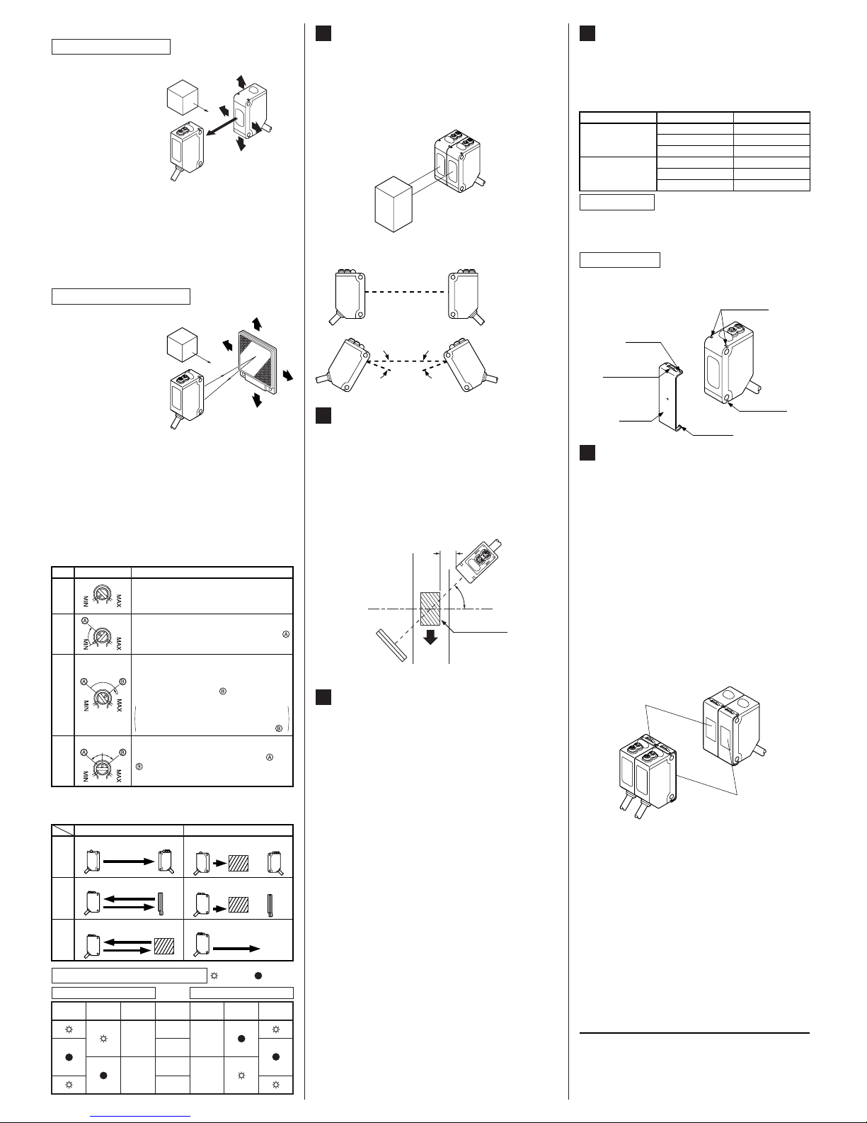
٨Part description
Operation mode switch
(Note 1)
L: Light-ON
D: Dark-ON
Operation indicator
(Orange) (Note 2)
Lights up when the
sensing output is
ON
Sensitivity adjuster
(Note 1)
Sensing range be-
comes longer when
turned clockwise
Stability indicator (Green)
(Note 1)
Lights up under the stable
light condition or the stable
dark condition
Notes: 1)
2)
Not incorporated on the thru-beam type sensor emitter.
It is the power indicator (green: lights up when the power
is ON) for the thru-beam type sensor emitter.
SPECIFICATIONS
1
Automatic interference
prevention function
Long sens-
ing range
70 to 200mm
(Note 4)
800mm
(Note 4)
15m 5m
(Note 3)
300mm
(Note 4)
10m 3m
(Note 3)
100mm
(Note 4)
Sensing range
Narrow-view
CX-422
CX-422-P
CX-423
CX-423-P
CX-412
CX-412-P
CX-491
CX-491-P
CX-493
CX-493-P
CX-424
CX-424-P
CX-421
CX-421-P
CX-411
PNP output
NPN output
Model No.
(Note 1)
CX-411-P
Item
With polarizing
filters (Note 2)
Long sens-
ing range
RetroreflectiveThru-beam Diffuse reflective
Type
20mA or less
25mA or less
12 to 24V DCr10% Ripple P-P 10% or lessSupply voltage
20mA or lessCurrent consumption
Emitter: 20mA or less
(CX-412غ: 25mA or less)
Receiver: 20mA or less
1mmorless
0.5mm or less
0.5mm or less
Repeatability
(perpendicular to sensing axis)
Opaque,
translucent or
transparent
object (Note 5)
Ǿ50mm or
more opaque
or translucent
object (Note 3)
Ǿ12mm or more opaque
object
Ǿ50mm or more
opaque, translu-
cent or specular
object (Note 3)
Opaque, translucent or transparent
object
Sensing object
Infrared LED
(modulated)
0.2mm23-core (thru-beam type sensor emitter: 2-core) cabtyre cable, 2m longCable
Enclosure: PBT, Lens: Acrylic, Indicator cover: Acrylic
Red LED
(modulated)
Red LED
(modulated) Red LED (modulated) Infrared LED (modulated)Emitting element
IP67 (IEC)Protection
-25to+55(No dew condensation or icing allowed), Storage: -30 to +70Ambient temperature
35 to 85% RH, Storage: 35 to 85% RHAmbient humidity
Incorporated (Two units of sensors can be mounted closely.)
Continuously variable adjusterSensitivity adjuster
Green LED (lights up when the
power is ON), located on the emitter
Power indicator
Green LED (lights up under stable light received condition or stable dark condition), thru-beam type sensor: located on the receiver
Stability indicator
Orange LED (lights up when the output is ON), thru-beam type sensor: located on the receiverOperation indicator
1ms or less
㧙
㧙
㧙㧙
㧙
(Note 6)
Response time
Switchable either Light-ON or Dark-ON
Incorporated
Output
Output operation
Short-circuit protection
<NPN output type>
NPN open-collector transistor
Maximum sink current: 100mA
Applied voltage: 30V DC or less (between output and 0V)
Residual voltage: 1V or less (at 100mA sink current)
0.4V or less (at 16mA sink current)
<PNP output type>
PNP open-collector transistor
Maximum source current: 100mA
Applied voltage: 30V DC or less (between output and +V)
Residual voltage: 1V or less (at 100mA source current)
0.4V or less (at 16mA source current)
RF-230 (Reflector): 1 pc.
Material
50g approx.
Emitter: 45g approx., Receiver: 50g approx.
Weight
Accessory
Notes: 1) The model No. with suffix '-J' is the M12 pigtailed type, '-Z' is the M8 connector type.
(e.g.) M12 pigtailed type: CX-411-J, M8 connector type: CX-411-Z
Use the connection cables as shown below. (Two sets are required for the thru-beam type sensor.)
<Connection cable for the M12 pigtailed type>
Type Model No. Cable length
2-core type CN-22-C2 2m
CN-22-C5 5m
4-core type CN-24-C2 2m
CN-24-C5 5m
<Connection cable for the M8 connector type>
Type Model No. Cable length
Straight type CN-24A-C2 2m
CN-24A-C5 5m
Elbow type CN-24AL-C2 2m
CN-24AL-C5 5m
2)
3)
4)
5)
6)
The model No. with suffix 'E' shown on the label affixed to the thru-beam type sensor is the emitter, 'D' shown on the label is the receiver.
Thru-beam type sensor emitter: CX-41غE, Thru-beam type sensor receiver: CX-41غD
The model No. of retroreflective type sensor with the suffix '-Y' is the sensor without the RF-230 reflector.
(e.g.) CX-491-Y
The retroreflective type sensor with polarizing filters may not stably detect specular
or glossy objects through transparent film since light is polarized by the transparent
film. For details, refer to ' RETROREFLECTIVE TYPE SENSOR WITH POLAR-
IZING FILTERS'.
The sensing range and the sensing object of the retroreflective type sensor is specified
fot the RF-230 reflector. The sensing range represents the actual sensing range of the
sensor. The sensing ranges itemized in 'A' of the table below may vary depending of the
shape of sensing object. Be sure to check the operation with the actual sensing object.
The sensing range of the diffuse reflective type sensor is specified for white non-
glossy paper (200 200mm) as the object.
The minimum sensing object of the diffuse reflectivenarrow-view type sensor is
Ǿ0.5mm copper wire.
By mounting interference prevention filters (PF-CX4-غ), two sets of the sensor can be mounted close together. For details, refer
to ' INTERFERENCE PREVENTION FILTER (OPTIONAL)'.
8
10
Sensing range
(A)
Reflector setting range
(B)
Sensor Reflector
Sensing
object
A
B
3m
0.1 to 3m
5m
0.1to5m
CX-491غCX-493غ
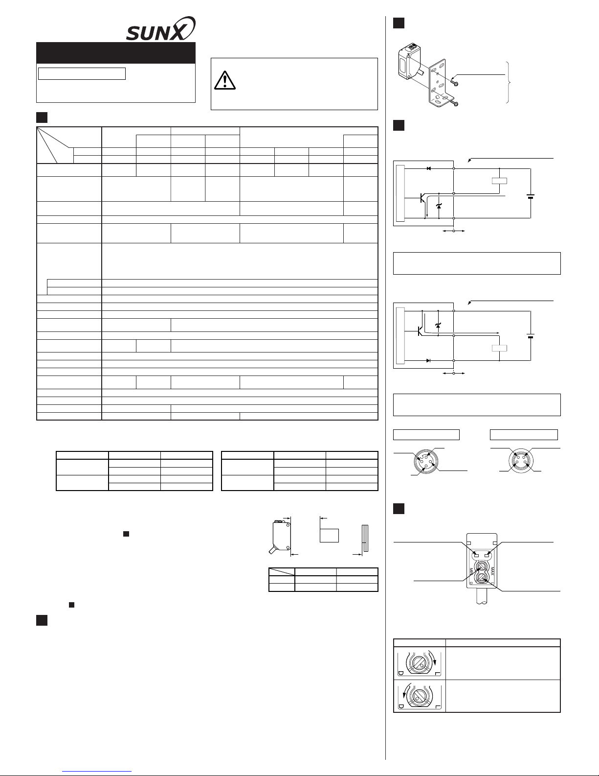
MOUNTING
3
٨The tightening torque should be 0.5N㨯m or less.
Sensor mounting
bracket
(Optional)
M3 (length 12mm)
screw with washers