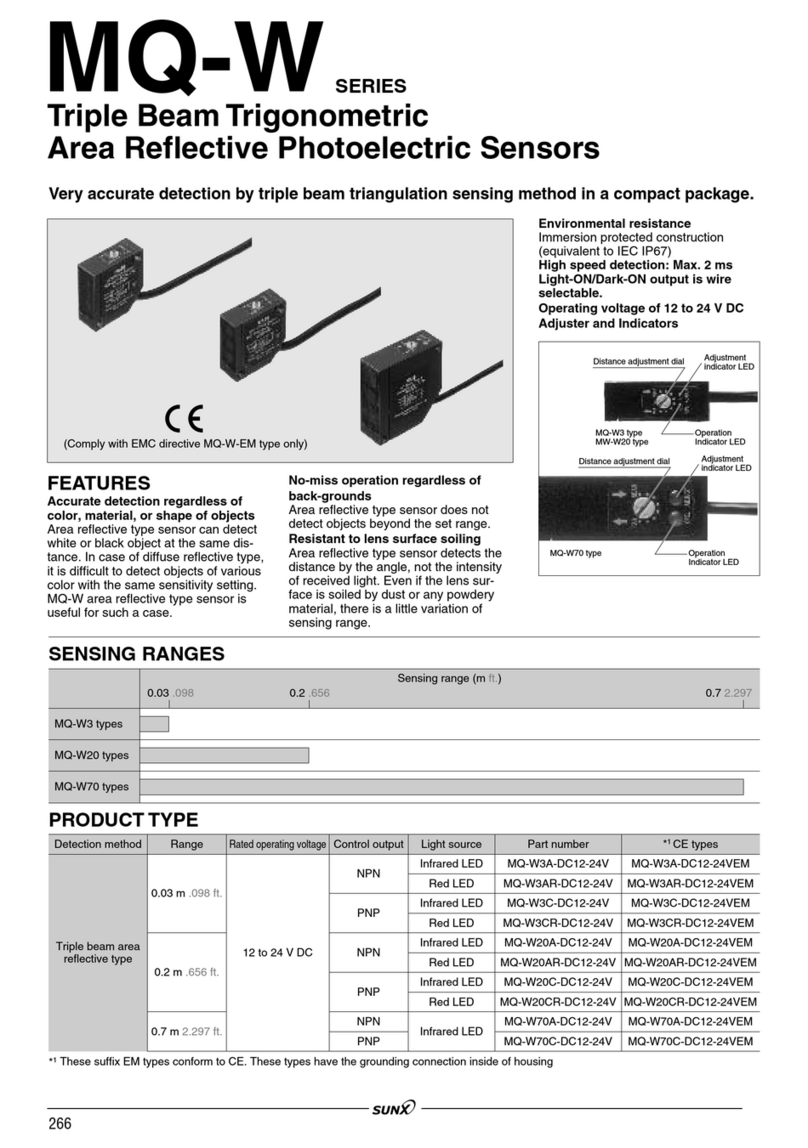
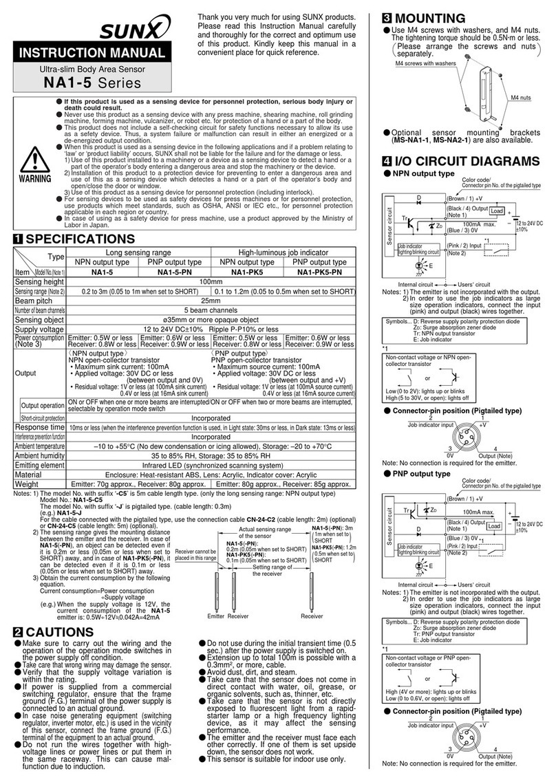
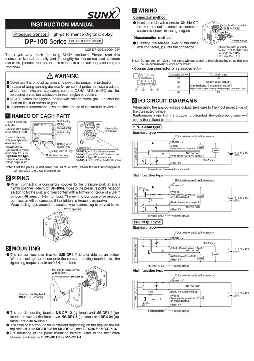
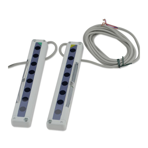
Sunx SF2-EH Series User manual

GROBAL SAFETY AREA SENSOR
Passes global safety standards!

Conforming to Latest
International Safety
Standards
1
Global Safety
The SF2-EH series complies with the IEC 61496-1/2 international standards, so that it can be used
in different countries throughout the world.
•CE marking based on Machine Directive and EMC Directive has been obtained.
[Type 4 based on IEC (EN) 61496-1/2, and Category 4 based on EN 954-1]
•UL and C-UL listings (IEC 61496-1/2) which are required for use in the united states and Canada
have been obtained.
•This series is also compatible with equipment conforming to OSHA (1910. 212/217), ANSI
(B11.1lB11.20) and ANSI/RIA 15.06 regulations.
Pursuit of Safety
It uses two independent CPUs, which mutually check the
safety conditions. High reliability fail-safe design is real-
ized by incorporating dual circuits for signal processing
and output.
Further, in order to ensure safety, FMEA (Failure Mode &
EffectAnalysis) has been used to prove safe operation.
Safety Design of SF2-EH series
The SF2-EH series checks by itself for any internal circuit
failure, cable breakage/short-circuit, or even abnormal incident
ambient light. If any error occurs, the SF2-EH series outputs the
same signal as when a beam is interrupted (OFF signal), so that
the machine is stopped and cannot restart.
Monitoring
section
Control
section
Emitter side Receiver side
Emitting circuit
Output
circuit
Signal process-
ing circuit
Mutual
check
Receiving circuit
Control
section
Monitoring
section
Control
section
Monitoring
section
Output
section
Output
section
Output
circuit
Signal process-
ing circuit
Emitting
element failure
Emitting
circuit failure
Cable breakage/
short-circuit
Cable breakage/
short-circuit
Receiving
element failure Output drive
circuit failure
Receiving
circuit failure
Amp
Abnormal
condition of CPU
CPU
Strong
extraneous light
SF2-EHSERIES

2
SF2-EH
Sensing range
10m
Sensing height
1,580
mm max.
Beam spread angle:
2.5°or less
Wide Area: 1,580mm10m
It realizes a wide sensing area with a
sensing height of 1,580mm max. (80
beam channels) and a long sensing
range of 10m.
Just one sensor can cover an area
where previously 2 sensors had to be
used.
Cable for series connection
SF2-CSL02 (Length: 200mm)
SF2-CSL05 (Length: 500mm)
Sensors Connectable in Series
Using the optional cable (SF2-CSL)
for series connection, maximum 4 sets
of sensors with a total of 192 beam
channels can be connected in series.
For example, in case of mounting the
sensors on the front, as well as, both
the sides of a danger region, previous-
ly separate wiring was required for
3 sets of sensors. But now, wiring
equivalent to that for only 1 set is
required, thus saving troublesome
wiring and cost.
12 beam
channels
80 beam
channels
Sensing height
1,580mm
220mm
Wide Variety
There are 13 models of sensors having
a sensing height ranging from 220mm
(12 beam channels) to 1,580mm (80
beam channels). The sensors can be
selected to suit the monitoring area of
the used equipment.
Further, PNP output equivalent type,
as well as, NPN output equivalent type
are available.
No Interference
•Beam spread angle 2.5or less
Since the beam spread angle is nar-
row (2.5° or less), it reduces the
effect of reflection from walls, etc.,
and interference from extraneous
light.
•Up to 12 sets mountable
In case of series connection or parallel
connection, interference can be pre-
vented for up to 4 sets, respectively.
Further, in case of series and parallel
mixed connection, up to 12 sets (total
192 beam channels) can be mounted.
Slit mask
•Convenient slit mask available
By using the optional slit mask
(OS-SF2-H), the amount of beam
emitted or received can be restrained
to reduce the effect of extraneous
light from other sensors, etc.
Exclusive Controller Not Required
Since an exclusive controller is not
required, there is no need to provide
space for it.
Further, the PNP output equivalent
type can be combined with an optional
safety relay unit (SRB-NA-R-C. 17/SX)
to create an intrusion detection sys-
tem.
Easy Maintenance
An optional front protection cover
(FC-SF2-H) is available, so that the
sensing face of the sensor can be pro-
tected in an adverse environment.
Further, if the front protection cover
becomes dirty or scratched, you can
just change the cover. The sensor,
itself, need not be changed.
Mounting Bracket Enables Easy Beam Alignment
The beam alignment is easy since
angle adjustment is possible with the
sensor mounting bracket (MS-SF2-1).
Solid aluminum case
All models have a solid aluminum case
with a thickness of 3mm. This case is
much stronger than previous cases, so
that the sensors can be used with
even greater confidence.

Beam pitch
Sensing height
20mm
Beam channel No.
0.5
m
Optional mating cable
SF2-CC3 Length: 3m
Weight: 410g approx.
8-core shielded cable, with connector on one
end, two cables per set
•Cable outer diameter: "6mm
•Connector outer diameter: "14mm max.
8-core shielded cable, with connector on both
ends, two cables per set
•Cable outer diameter: "6mm
•Connector outer diameter: "14mm max.
It can connect two sensors in series.
8-core shielded cable, two cables per set
•Cable outer diameter: "6mm
•Connector outer dimensions: 35mm max.
Length: 7m
Weight: 890g approx.
Length: 10m
Weight: 1.2kg approx.
Length: 10m
Weight: 1.2kg approx.
Length: 200mm
Weight: 150g approx.
Length: 500mm
Weight: 170g approx.
SF2-CC7
SF2-CC10
SF2-CCJ10
SF2-CSL02
SF2-CSL05
SF2-EH12
SF2-EH16
SF2-EH20
SF2-EH24
SF2-EH28
SF2-EH32
SF2-EH36
SF2-EH40
SF2-EH48
SF2-EH56
SF2-EH64
SF2-EH72
SF2-EH80
SF2-EH12-N
SF2-EH16-N
SF2-EH20-N
SF2-EH24-N
SF2-EH28-N
SF2-EH32-N
SF2-EH36-N
SF2-EH40-N
SF2-EH48-N
SF2-EH56-N
SF2-EH64-N
SF2-EH72-N
SF2-EH80-N
12
16
20
24
28
32
36
40
48
56
64
72
80
220
300
380
460
540
620
700
780
940
1,100
1,260
1,420
1,580
SF2-EH
3
APPLICATIONS
Guarding space around working robot
Safeguard for press machine
Safeguard for special purpose machine
SF2-EH80
SF2-EH80
SF2-EH32
Hand
SF2-EH48
ORDER GUIDE
Sensors
Appearance Sensing range Model No.
Number of
beam channels
Sensing
height (mm)
PNP output equivalent type NPN output equivalent type
0.3 to 10m
Mating cable is not supplied with the sensor. Please order it separately.
Mating cables
Type Appearance Model No. Description
Cable with con-
nector on one
end
Cable with con-
nector on both
ends
Cable for series
connection

4
SF2-EH
ORDER GUIDE
Spare parts
Designation Model No. Description
Sensor mounting
bracket A set of brackets for both the emitter
and the receiver
A set of brackets for both the emitter
and the receiver
Sensing object ("30mm) for daily
check
MS-SF2-1
MS-SF2-2
SF2-EH-TR
Intermediate
supporting
bracket
Test rod
Sensor mounting
bracket
Four bracket set
Eight M4 (length 8mm) hexagon-
socket-head bolts and eight spring
washers are attached.
Intermediate
supporting bracket
Receiver
surface
Set of 2 Nos. each of U-shaped intermedi-
ate supporting bracket and L-shaped inter-
mediate supporting bracket
Two M4 (length 6mm), two M4 (length
8mm) hexagon-socket-head bolts, two
nuts and two spring washers are
attached.
FC-SF2-H12 FC-SF2-H16 FC-SF2-H20 FC-SF2-H24 FC-SF2-H28 FC-SF2-H32 FC-SF2-H36 FC-SF2-H40 FC-SF2-H48 FC-SF2-H56 FC-SF2-H64 FC-SF2-H72 FC-SF2-H80
OS-SF2-H12 OS-SF2-H16 OS-SF2-H20 OS-SF2-H24 OS-SF2-H28 OS-SF2-H32 OS-SF2-H36 OS-SF2-H40 OS-SF2-H48 OS-SF2-H56 OS-SF2-H64 OS-SF2-H72 OS-SF2-H80
MC-SF2EH-12 MC-SF2EH-16 MC-SF2EH-20 MC-SF2EH-24 MC-SF2EH-28 MC-SF2EH-32 MC-SF2EH-36 MC-SF2EH-40 MC-SF2EH-48 MC-SF2EH-56 MC-SF2EH-64 MC-SF2EH-72 MC-SF2EH-80
SRB-NA-R-C.17/SX
Front
protection
cover
Slit
mask
Front
protection
bracket
Safety relay unit
(Note)
OPTIONS
Designation
Designation Model No. Description
Applicable beam
channels
It protects
front lens.
Front protection cover Slit mask
Front protection cover
Slit mask
Safety relay unit
X1S11S21
X2S12S22
133123
14
K2
K1
3224
Note: The model Nos. given above denote a single unit, not a pair of units.
PNP output equivalent type relay unit
•Complies with safety categories up to 4
based on EN 954-1
•
Can be used to construct an intrusion
detection system with a high level of safety
Front protection bracket
It protects front face
from damage due to
striking of an object.
Model
No.
For 12 beam
channels
For 16 beam
channels
For 20 beam
channels
For 24 beam
channels
For 28 beam
channels
For 32 beam
channels
For 36 beam
channels
For 40 beam
channels
For 48 beam
channels
For 56 beam
channels
For 64 beam
channels
For 72 beam
channels
For 80 beam
channels
Model
No.
Model
No.
The slit mask restrains the
amount of beam emitted or
received and hence
reduces the interference
between neighbouring
sensors.
However, the sensing
range reduces when the
slit mask is used.
Sensing range
•
Slit on the emitter side: 4m
•
Slit on the receiver side:
5m
•Slit on both sides: 2m
Note: For further details, refer to P.14 ~ for the safety relay unit.

Sensing height
Sensing range
Beam pitch
Beam spread angle
Sensing object
Supply voltage
Current consumption
Outputs(OSSD 1, OSSD 2)
(Note 1)
Output operation
Short-circuit protection
Response time
Emitter
Receiver
Test input function
Interference prevention function
Protection
Ambient temperature
Ambient humidity
Ambient illuminance
EMC
Voltage withstandability
Insulation resistance
Vibration resistance
Shock resistance
Emitting element
Material
Cable
Cable extension
Weight
Accessories
220mm 300mm 380mm 460mm 540mm 620mm 700mm 780mm 940mm 1,100mm1,260mm1,420mm1,580mm
0.3 to 10m
20mm
2.5°or less [for sensing range exceeding 3m (conforming to IEC 61496-2)]
"30mm or more opaque object
24V DC15%
200mA or less
<PNP output equivalent type>
Semiconductor output (PNP output equivalent) 2 outputs
•Maximum source current: 300mA
•Applied voltage: same as supply voltage
•Residual voltage: 2.5V or less (at 300mA source current)
ON when all beams are received/OFF when one or more beams are interrupted
(It also turns OFF in case of any abnormality in the sensor or the synchronization signal.)
Incorporated
ONnOFF: 15ms or less, OFFnON: 20ms or less
Emitting indicator: Green LED (lights up under normal emission)
Emission stop indicator: Orange LED (lights up when emission stops)
Fault indicator: Yellow LED (lights up or blinks if the sensor fails)
OSSD ON indicator: Green LED (lights up when OSSDs are ON)
OSSD OFF indicator: Red LED (lights up when OSSDs are OFF)
Incident beam indicator: Green/Red LED [lights up in red with intensity proportional to the incident light intensity for reference
channel (second channel from cable side), lights up in green when all beams are received]
Fault indicator: Yellow LED (lights up or blinks if the sensor fails)
Incorporated
Series connection: 4 sets max., however total 192 beam channels max.
Incorporated Parallel connection: 4 sets max., however total 192 beam channels max.
Series and parallel mixed connection: 12 sets max., however total 192 beam channels max.
IP65 (IEC)
10 to55°C (No dew condensation or icing allowed), Storage:25 to70°C
30 to 85% RH, Storage: 30 to 95% RH
Sunlight: 20,000?x at the light-receiving face, Incandescent light: 3,500?x at the light-receiving face
Emission: EN50081-2, Immunity: EN50082-2 and IEC 61496-1
1,000V AC for one min. between all supply terminals connected together and enclosure
20MΩ, or more, with 500V DC megger between all supply terminals connected together and enclosure
10 to 55Hz frequency, 0.75mm amplitude in X, Y and Z directions for two hours each
300m/s2acceleration (30G approx.) in X, Y and Z directions for three times each
Infrared LED (Emission wavelength: 870nm)
Enclosure: Aluminum, Cap: ABS
8-core (0.3mm24-core, 0.2mm24-core) shielded cable, 0.5m long, with a connector at the end
mUse together with the optional mating cable
Extension up to total 27m is possible, for both emitter and receiver, with optional mating cables.
1.1kg approx. 1.3kg approx. 1.5kg approx. 1.7klg approx. 1.9kg approx. 2.2kg approx. 2.4kg approx. 2.6kg approx. 3.1kg approx. 3.5kg approx. 4.0kg approx. 4.4kg approx. 4.9kg approx.
MS-SF2-1 (Sensor mounting bracket): 1 set, MS-SF2-2 (Intermediate supporting bracket): (Note 2), SF2-EH-TR (Test rod): 1 No.
12 16 20 24 28 32 36 40 48 56 64 72 80
SF2-EH12 SF2-EH16 SF2-EH20 SF2-EH24 SF2-EH28 SF2-EH32 SF2-EH36 SF2-EH40 SF2-EH48 SF2-EH56 SF2-EH64 SF2-EH72 SF2-EH80
SF2-EH12-N SF2-EH16-N SF2-EH20-N SF2-EH24-N SF2-EH28-N SF2-EH32-N SF2-EH36-N SF2-EH40-N SF2-EH48-N SF2-EH56-N SF2-EH64-N SF2-EH72-N SF2-EH80-N
SF2-EH
5
SPECIFICATIONS
Notes: 1) OSSD stands for ‘Output Signal Switching Device’.
Notes: 2) MS-SF2-2 (intermediate supporting bracket) is attached with sensors having 24, or more, beam channels.
The number of attached intermediate supporting brackets is different depending on the sensor as follows.
SF2-EH24(-N), SF2-EH28(-N), SF2-EH32(-N), SF2-EH36(-N), SF2-EH40(-N), SF2-EH48(-N), SF2-EH56(-N): 1 set
SF2-EH64(-N), SF2-EH72(-N), SF2-EH80(-N): 2 sets
Model
No.
Item
PNP output equivalent type
NPN output equivalent type
<NPN output equivalent type>
Semiconductor output (NPN output equivalent) 2 outputs
•Maximum sink current: 300mA
•Applied voltage: same as supply voltage
•Residual voltage: 2V or less (at 300mA sink current)
Indicators
Environmental resistance
Number of beam
channels
( )
6
SF2-EH
I/O CIRCUIT AND WIRING DIAGRAMS
NPN output
equivalent type
I/O circuit diagram Wiring diagram
Sensor circuit
2
3
1
7
4
8
5
6
Sensor circuit
Load
Load
6
5
4
8
2
1
7
24V DC
15%
m1
Used for interference
prevention function.
(Brown)V
(Brown)V
(Pink) Test input
(Violet) Master/slave selection input (Note)
(Blue) 0V
(Gray) Interference
prevention ()
(Gray/Black) Interference
prevention ()
(Gray) Interference
prevention ()
(Gray/Black) Interference
prevention ()
(Orange) Synchronization ()
(Orange/Black)
Synchronization ()
(Orange) Synchronization ()
(Black) OSSD 1
(White) OSSD 2
(Blue) 0V
(Orange/Black)
Synchronization (
)
Users’circuit
Internal circuit
Users’circuitInternal circuit
Used for interference
prevention function.
Emitter
Receiver
300mA max.
300mA max.
Connector pin No.
Color code of mating cable
3
24V DC
15%
Load Load
Brown
Pink
Violet (Note)
Blue
Gray
Gray/Black
Orange
Orange/Black
Orange/Black
Orange
Gray
Gray/Black
Brown
Black
White
Blue
m1
Used for interference
prevention function.
Used for interference
prevention function.
1
Master/slave
selection input
7
0V
2V6
Synchronization ()
5
Synchronization ()
8
Interference
prevention ()
3
Test input
4
Interference
prevention ()
Emitter
Connector pin No.
Color code of mating cable
1
OSSD 2
7
0V
2V
3
OSSD 1
6
Synchronization ()
5
Synchronization ()
8
Interference
prevention ()
4
Interference
prevention ()
Receiver
Note: Refer to P.11 for master/slave selection input.
or
m1
Non-voltage contact or
NPN open-collector transistor
Low (0V): emission
High (V or open): emission stopped
CAUTION
Use a safety control circuit for the load
(FSD).
•When the sensor is in the light received condition (ON
state), the receiver self-diagnoses the output circuit. For
this purpose, the output transistor goes to the OFF state
periodically. (Refer to the figure of output condition given
at the right.)
If the OFF signal is fed back, the receiver judges the out-
put circuit as normal. If the OFF signal is not fed back, the
receiver judges that the output circuit or the wiring is
abnormal, and the output is maintained in the OFF state.
•The frequency or the period for which the output transistor
turns OFF does not change even for the maximum con-
nected set No. of 4 sets connected in series.
Output waveform (when output is ON)
Take care of the input response time of the
equipment connected to the sensor, since there is
a possibility of the equipment malfunctioning due
to the sensor OFF signal.
20ms max.
Light interrupted
Light received
OFF
ON
Receiver
condition
Output
condition
7ms
15ms max.
11
No. of pulses (No. of 1’s in the figure) in 7ms... 2
Pulse width (width of 1in the figure) (!s)... 3
Sum of the pulse widths in 7ms (product of 2and 3) (!s)
1 to 2
200
400 max.

SF2-EH
7
I/O CIRCUIT AND WIRING DIAGRAMS
PNP output
equivalent type
I/O circuit diagram Wiring diagram
Sensor circuit
2
3
1
7
4
8
5
6
Sensor circuit
Load Load
6
5
4
8
2
3
1
7
24V DC
15%
m1
Used for interference
prevention function.
(Brown)V
(Brown)V
(Pink) Test input
(Violet) Master/slave selection input (Note)
(Blue) 0V
(Gray) Interference
prevention ()
(Gray/Black) Interference
prevention ()
(Gray) Interference
prevention ()
(Gray/Black) Interference
prevention ()
(Orange) Synchronization ()
(Orange/Black)
Synchronization ()
(Orange) Synchronization ()
(Black) OSSD 1
(White) OSSD 2
(Blue) 0V
(Orange/Black)
Synchronization (
)
Users’circuit
Internal circuit
Users’circuitInternal circuit
Used for interference
prevention function.
Emitter
Receiver
300mA max.
300mA max.
Connector pin No.
Color code of mating cable
24V DC
15%
Load Load
Brown
Pink
Violet (Note)
Blue
Gray
Gray/Black
Orange
Orange/Black
Orange/Black
Orange
Gray
Gray/Black
Brown
Black
White
Blue
Used for interference
prevention function.
Used for interference
prevention function.
1Master/slave
selection input
70V
2V6
Synchronization ()
5
Synchronization ()
8
Interference
prevention ()
3
Test input
4
Interference
prevention ()
1
OSSD 2
7
0V
2V
3
OSSD 1
6
Synchronization ()
5
Synchronization ()
8
Interference
prevention ()
4
Interference
prevention ()
Emitter
Receiver
m1
Connector pin No.
Color code of mating cable
Note: Refer to P.11 for master/slave selection input.
or
m1
Non-voltage contact or
NPN open-collector transistor
Low (0V): emission
High (V or open): emission stopped
CAUTION
Use a safety relay unit or a safety control
circuit having equivalent safety for the load
(FSD).
•When the sensor is in the light received condition (ON
state), the receiver self-diagnoses the output circuit. For
this purpose, the output transistor goes to the OFF state
periodically. (Refer to the figure of output condition given
at the right.)
If the OFF signal is fed back, the receiver judges the out-
put circuit as normal. If the OFF signal is not fed back, the
receiver judges that the output circuit or the wiring is
abnormal, and the output is maintained in the OFF state.
•The frequency or the period for which the output transistor
turns OFF does not change even for the maximum con-
nected set No. of 4 sets connected in series.
Output waveform (when output is ON)
Take care of the input response time of the
equipment connected to the sensor, since there is
a possibility of the equipment malfunctioning due
to the sensor OFF signal.
20ms max.
Light interrupted
Light received
OFF
ON
Receiver
condition
Output
condition
7ms
15ms max.
11
No. of pulses (No. of 1’s in the figure) in 7ms... 2
Pulse width (width of 1in the figure) (!s)... 3
Sum of the pulse widths in 7ms (product of 2and 3) (!s)
1 to 2
200
400 max.

8
SF2-EH
I/O CIRCUIT AND WIRING DIAGRAMS
PRECAUTIONS FOR PROPER USE
PNP output
equivalent type
Example of a connection of safety relay unit (SRB-NA-R-C.17/SX)
Note: When using manual reset, connect terminals X1 and X2 of the safety relay unit as shown in the above diagram.
Note: When using automatic reset, short terminals X1 and X3 of the safety relay unit.
In order to comply with safety
standards, be sure to use
separate power supplies for
the safety relay unit power
supply E2 and the safety area
sensor power supply E1, and
also make sure that they are
both 0V.
In addition, the input signal
(OFF signal) for the safety relay
unit (SRB-NA-R-C.17/SX)
should be 30ms or more.
K1 K2
Control circuit
KA
K2
K1
K1
E2
E1
K2
KB
KA
KB
14D24
13 23
N
L1
OSSD 1 (Black)
OSSD 2 (White)
X2 X3S2S1C1
F1
CX1
Power switch0V0V
24V DC
24V DC15%
V(Brown)
Master/slave selection input(Violet)
V(Brown)
0V(Blue)
0V(Blue)
Synchronization () (Orange)
Synchronization () (Orange/Black) Synchronization () (Orange/Black)
Synchronization () (Orange)
Interference prevention (
)(Gray)
Interference prevention (
)(Gray/Black)
Interference
prevention (
)
(Gray)
Interference
prevention (
)
(Gray/Black)
Safety relay unit
Test input(Pink)
Emitter
Receiver
Reset
switch
Wiring
• Make sure to carry out the wiring in the power supply off
condition.
• Verify that the supply voltage variation is within the rating.
• If power is supplied from a commercial switching regulator,
ensure that the frame ground (F.G.) terminal of the power
supply is connected to an actual ground.
• In case noise generating equipment (switching regulator,
inverter motor, etc) is used in the vicinity of this sensor,
connect the frame ground (F.G.) terminal of the equipment
to an actual ground.
• Do not run the wires together with high-voltage lines or
power lines or put them in the same raceway. This can
cause malfunction due to induction.
Others
• Do not use during the initial transient time (5 sec.) after the
power supply is switched on.
• Avoid dust, dirt and steam.
• Take care that the sensor does not come in direct contact
with water, oil, grease, or organic solvents, such as, thin-
ner, etc.
• Take care that the sensor is not directly exposed to fluores-
cent light from a rapid-starter lamp or a high frequency
lighting device, as it may affect the sensing performance.

SF2-EH
9
PRECAUTIONS FOR PROPER USE
To use this product in the U.S.A., refer to OSHA
1910. 212 and OSHA 1910. 217 for installation,
and in Europe, refer to prEN 999 as well.
Observe your national and local requirements
before installing this product.
• Refer to the instruction manual enclosed with this
product for detailed instructions.
•Make sure to carry out the test run before regular
operation.
•
This safety system is for use only on machinery in which
the dangerous parts can be stopped immediately, either by
an emergency stop unit or by disconnecting the power
supply. Do not use this system with machinery which
cannot be stopped at any point in its operation cycle.
Sensing area
Correct mounting method
Wrong mounting method
Safety distance
•Safety distance is calculated based on the following equa-
tion when a person moves perpendicular (normal intru-
sion) to the sensing area of the sensor.
•Equation 1DKTC
•D: Safety distance (mm)
Minimum required distance between the surface of the sensing
area and dangerous part of machine.
•K:
Intrusion velocity of operator’s body (hand, finger, etc.) (mm/sec.)
Normally taken as 2,000 (mm/sec.) for calculation.
•T: Response time of total equipment (sec.)
TTmTSF2
Tm: Maximum halt time of device (sec.)
TSF2: Response time of the SF2-EH series 0.015 (sec.)
•C:Additional distance calculated from the size of the minimum
sensing object of the area sensor (mm)
Note that the value of C is not 0 or less.
C8(d14)
d: Minimum sensing object diameter 30 (mm)
Make sure to install this product such that any part
of the human body must pass through its sensing
area in order to reach the dangerous parts of the
machinery. If the human body is not detected,
there is a danger of serious injury or death.
Calculate the safety distance correctly, and
always maintain a distance which is equal to or
greater than the safety distance, between the
sensing area of this sensor and the dangerous
parts of the machinery.
If the safety distance is miscalculated or if suffi-
cient distance is not maintained, there is a danger
of serious injury or death.
For use in Europe (as per prEN 999)
•Equation 2DK(TsTcTSF2Tbm)Dpf
•D: Safety distance (mm)
Minimum required distance between the surface of the sensing
area and dangerous part of machine.
•K:
Intrusion velocity of operator’s body (hand, finger, etc.) (mm/sec.)
Normally taken as 63 (inch/sec.)c1,600 (mm/sec.) for calcula-
tion.
•Ts: Halt time calculated from the operation time of the control ele-
ment (air valve, etc.) (sec.)
•Tc: Maximum response time of the control circuit required for
functioning the brake. (sec.)
•TSF2: Response time of the SF2-EH series 0.015 (sec.)
•Tbm: Additional halt time tolerance for the brake monitor (sec.)
TbmTa(TsTc)
Ta: Setting time of brake monitor (sec.)
•Dpf:Additional distance calculated from the size of the minimum
sensing object of the area sensor (mm)
Note that the value of Dpf is not 0 or less.
Dpf3.4(d0.276) (inch)
Dpf3.4(d7) (mm)
d:
Minimum sensing object diameter 1.2 (inch)
c
30 (mm)
For use in U.S.A. (as per ANSI B11.19)
Dangerous part Sensing
area
Emitter Receiver
Beam axis
D
Dangerous part
of machine
Dangerous
part
Sensing area
Protective
structure
Dangerous
part
Sensing area
Sensing area
Dangerous
part

10
SF2-EH
PRECAUTIONS FOR PROPER USE
Influence of reflective surface
Install the sensor by considering the effect of near-
by reflective surfaces and taking suitable counter-
measures. Failure to do so may cause the sensor
not to detect, resulting in serious injury or death.
•Keep the minimum distance given below, between the
sensor and a reflective surface.
Side view Top view
Distance
between
emitter and
receiver, L
Allowable
setting
distance, D
0.3 to 3m
3 to 10m
0.16m
Ltan $
L0.052 (m)
Mounting
•When mounting the sensor, the tightening torque should
be 2Nm or less.
•Choose the mounting direction for the sensor mounting
bracket based on the mounting direction (side or back),
and temporarily tighten the brackets with the two hexagon-
socket-head bolts for adjusting the mounting angle (M4,
length 8mm). Tighten the two hexagon-socket-head bolts
securely, after beam alignment.
Note: The beam spread angle for this sensor is 2.5(with L>3m) as
required by IEC 61496-2. However, install this sensor away from the
reflective surfaces, assuming a beam spread angle of3to provide
for misalignment, etc., during installation.
Mounting of sensor mounting bracket (MS-SF2-1)
<Side mounting><Back mounting>
Mounting of intermediate supporting bracket (MS-SF2-2)
1Choose the mounting direction for the L- and U-shaped
intermediate supporting brackets based on the mounting
direction (side or back), and temporarily tighten the
mounting brackets with the hexagon-socket-head bolt
(M4, length 8mm). Tighten it securely, after beam align-
ment.
2
Clasp the body of the sensor with the U-shaped interme-
diate supporting bracket, and temporarily tighten with the
hexagon-socket-head bolt (M4, length 6mm) for position
adjustment. Tighten it securely, after beam alignment.
<Side mounting><
Back mounting>
<Side mounting><Back mounting>
Note: The above drawing shows the intermediate supporting bracket mount-
ed on the emitter. In case of mounting on the receiver, note that the
intermediate supporting bracket is upside down.
Mounting of cable for series connection (SF2-CSL)
1
Remove four M4 screws (length 10mm) on the main sen-
sor and the sub sensor as given below.
2As shown below, mount the cable for series connection
at the place on the main sensor and the sub sensor from
where the screws have been removed.
Reflective ceiling Reflective surface
Reflective floor
Emitter
(Note)
Emitter
Receiver
Receiver
Sensing area 3
3
DD
L
D
L
Hexagon-socket-head
bolt Hexagon-socket-head bolt
U-shaped intermediate
mounting bracket
L-shaped intermediate
mounting bracket
Hexagon nut Hexagon nut
Sensor
Beam emitting or
receiving surface
U-shaped intermediate
mounting bracket
Hexagon-socket-head
bolt for position adjustment Hexagon-socket-head
bolt for position adjustment
Beam emitting or
receiving surface
Sub sensor Main sensor
Cables with connector
Screws
Cable for series connection
Sensor mounting
bracket Sensor mounting
bracket
Hexagon-socket-head
bolts for adjusting the
mounting angle
Sensor
Beam emitting or receiving surface Beam emitting or receiving surface
Projections
Projections
Projection of sensor
mounting bracket
Concavity in sensor
main body
0246810
0
0.2
0.4
0.6
0.8
Allowable setting distance D (m)
Distance between emitter and receiver L (m)
Allowed setting area
Unallowed setting area

Synchronization ()
(Orange)
Interference
prevention ()
(Gray)
Synchronization ()
(Orange/Black)
Synchronization ()
(Orange)
Synchronization ()
(Orange/Black)
Interference
prevention ()
(Gray/Black)
Emitter 1 Receiver 1 Emitter 2 Receiver 2
Synchronization ()
(Orange)
Interference
prevention ()
(Gray)
Synchronization ()
(Orange/Black)
Synchronization ()
(Orange)
Synchronization ()
(Orange/Black)
Interference
prevention ()
(Gray/Black)
Emitter 1 Receiver 1 Emitter 2 Receiver 2
Master/slave selection input
(Violet)
Master/slave selection input
(Violet)
Connect to 0V Connect to V or open
Synchronization ()
(Orange)
Synchronization ()
(Orange/Black)
Emitter 1 Receiver 1
Master/slave selection input
(Violet)
Interference
prevention ()
(Gray) Synchronization ()
(Orange)
Synchronization ()
(Orange/Black)
Interference
prevention ()
(Gray/Black)
Emitter 2 Receiver 2
Master/slave selection input
(Violet)
Connect to 0V Connect to V or open
Synchronization ()
(Orange)
Synchronization ()
(Orange/Black)
Emitter Receiver
Master/slave selection input
(Violet)
Cable for serial connection
(optional)
SF2-CSL02 (Length: 200mm)
SF2-CSL05 (Length: 500mm)
Connect to 0V
Synchronization ()
(Orange)
Interference
prevention ()
(Gray)
Synchronization ()
(Orange/Black)
Synchronization ()
(Orange)
Synchronization ()
(Orange/Black)
Interference
prevention ()
(Gray/Black)
Emitter 1 Receiver 1 Emitter 2 Receiver 2
Master/slave selection input
(Violet)
Master/slave selection input
(Violet)
Connect to 0V Connect to V or open
SF2-EH
11
PRECAUTIONS FOR PROPER USE
Test input function
•
The emission is halted when the test input wire (pink) is connect-
ed toV or kept open. The test input is useful for a start-up
check since the sensing output can be switched ON/OFF without
the sensing object.
Non-voltage contact or
NPN open-collector transistor
Low (0V): emission
High (V or open): emission stopped
or
mSignal condition
Note: When test input function is not used, make sure to connect the test
input wire (pink) to 0V.
Interference prevention function
•
Interference can be prevented between 4 sets max. (192 beam
channels max.) for series connection, 4 sets max. (192 beam
channels max.) for parallel connection, and 12 sets max. (192
beam channels max.) for series and parallel mixed connection.
In this case, connect the respective interference () (gray) and
interference () (gray/black) of the adjacent sensors.
Sensor A Sensor B
Master/slave selection input
•
In case of parallel connection, or series and parallel mixed con-
nection, before switching on the power supply, connect the mas-
ter/slave selection input (violet) of Sensor A, as master, to 0V
and connect the master/slave selection input (violet) of Sensor
B, as slave, toV or open.
The master/slave selection is done only once at the time of
switching on of the power supply. If selection is done after
switching on of the power supply, it does not change.
Further, if the master/slave selection input is kept open when the
sensor is set as slave, ensure to insulate it.
•
In case of series connection or when using 1 set, connect the
master/slave selection input (violet), as master, to 0V.
Connection
•
When the danger region can
be approached from two or
more directions, multiple sets
of emitters and receivers
should be connected in
series. When a beam of any
set is interrupted, the output
turns OFF.
Series connection
[4 sets max. (192 beam channels max.) connectable]
•
In case there are two, or more, danger regions which can be
approached from a single direction only, multiple sets of emitters
and receivers can be connected in parallel by connecting their
interference prevention wires to individually monitor the danger
regions. Since the outputs are separate, only the output of the
sensor whose beams are interrupted is turned OFF.
Parallel connection
[4 sets max. (192 beam channels max.) connectable]
Sensor A
•
In case there are two, or more, danger regions which can be
approached from two or more directions, multiple sets of emitters
and receivers can be connected in series and parallel mixed
combination. For the sensors connected in series, the output
turns OFF if the beams of any of these sensors are interrupted.
For the sensors connected in parallel, the output of only the sen-
sor whose beams are interrupted turns OFF.
Serial/parallel mixed connection
[12 sets max. (192 beam channels max.) connectable]
Sensor A
Sensor B
Sensor B
(Pink) Test input
(Blue) 0V
Sensor A Sensor B

12
SF2-EH
Model No.
SF2-EH12(-N)
SF2-EH16(-N)
SF2-EH20(-N)
SF2-EH24(-N)
SF2-EH28(-N)
SF2-EH32(-N)
SF2-EH36(-N)
SF2-EH40(-N)
SF2-EH48(-N)
SF2-EH56(-N)
SF2-EH64(-N)
SF2-EH72(-N)
SF2-EH80(-N)
ABCDEFGH
220 312 346 362 ————
300 392 426 442 ————
380 472 506 522 ————
460 552 586 602 332 —280 —
540 632 666 682 362 —320 —
620 712 746 762 402 —360 —
700 792 826 842 442 —400 —
780 872 906 922 482 —440 —
940 1,032 1,066 1,082 562 —520 —
1,100 1,192 1,226 1,242 642 —600 —
1,260 1,352 1,386 1,402 488 0,976 446 0,892
1,420 1,512 1,546 1,562 542 1,084 500 1,000
1,580 1,672 1,706 1,722 595 1,190 574 1,148
SF2-EH(-N)
Sensor
Assembly dimensions
Mounting drawing for the sensor on which the sensor mounting brackets and the intermediate supporting brackets are mounted
<Side mounting><Back mounting>
DIMENSIONS (Unit: mm)
Note: MS-SF2-2 (intermediate supporting bracket) is attached with sensors having 24, or
more, beam channels.
The number of attached intermediate supporting brackets is different depending on
the sensor as follows.
SF2-EH24(-N), SF2-EH28(-N), SF2-EH32(-N), SF2-EH36(-N), SF2-EH40(-N),
SF2-EH48(-N), SF2-EH56(-N): 1 set
SF2-EH64(-N), SF2-EH72(-N), SF2-EH80(-N): 2 sets
10 11
(83.5)
(44.8)
16
C D B
35 18
5.5
(70)
50 32.5
10 F
E
15.5
G
H
20
76.2
A
33
Fault indicator
(Yellow)
OSSD OFF
indicator (Red)
Emitting indicator (Green) Incident beam
indicator
(Green•Red)
OSSD ON
indicator
(Green)
Emission stop
indicator (Orange)
Fault indicator (Yellow)
Beam
pitch
32.5 50 5.5
18 35
10
(24)
(53)
ACD
76.2
20
15.5
11
10
G
H
33
E
F
B
Beam
pitch
Fault indicator
(Yellow)
OSSD OFF
indicator (Red)
Emitting indicator
(Green)
Incident beam indicator
(Green•Red)
OSSD ON indicator
(Green)
Emission stop
indicator (Orange)
Fault indicator
(Yellow)
Emitter Receiver Emitter Receiver

32
32
57
72
Protection
bar bracket 32
32
57
72
View A View B
(49)
"15
Intermediate
supporting bracket
for protection bar
Protection bar
H
20
A
AB
Sensing height
Beam pitch
SF2-EH
13
MS-SF2-1
Sensor mounting
bracket (Accessory)
DIMENSIONS (Unit: mm)
12.3
5.5 0.3
1
(6)
(17.5)
32.5
20
"12
18
50
35
25
t 2.6
"22
12
4
48
8.5 t 2
(9)
5
M4
2-R8
10
13.5
3
28.5 18.5
41.5
(56.5)
33
20
30
20
25
(35)
13
26
18.5
15
22.8
46.5
32.5
2610.5 16
10
39
46 15.7
t 2
5.5 6
5.5
5.5
5.5
4.5
6
11
3-R5.5
6
Material: Cold rolled carbon steel (SPCC)
(Uni-chrome plated)
Four bracket set
Eight M4 (length 8mm) hexagon-
socket-head bolts and eight spring
washers are attached.
MS-SF2-2 Intermediate supporting bracket (Accessory)
U-shaped intermediate supporting bracket
L-shaped intermediate supporting bracket
Material: Cold rolled carbon steel (SPCC)
(Uni-chrome plated)
Set of 2 Nos. each of U-shaped intermedi-
ate supporting bracket and L-shaped inter-
mediate supporting bracket
Two M4 (length 6mm), two M4
(length 8mm) hexagon-socket-head
bolts, two nuts and two spring
washers are attached.
Material: Cold rolled carbon steel (SPCC)
(Uni-chrome plated)
MC-SF2EH-
Front protection bracket (Optional)
Model No.
SF2-EH12(-N)
SF2-EH16(-N)
SF2-EH20(-N)
SF2-EH24(-N)
SF2-EH28(-N)
SF2-EH32(-N)
SF2-EH36(-N)
SF2-EH40(-N)
SF2-EH48(-N)
SF2-EH56(-N)
SF2-EH64(-N)
SF2-EH72(-N)
SF2-EH80(-N)
AH
220 322
300 402
380 482
460 562
540 642
620 722
700 802
780 882
940 1,042
1,100 1,202
1,260 1,362
1,420 1,522
1,580 1,682
Note: The intermediate supporting bracket for protection bar is an accessory for units with beam axis of 40 or above. Use it if there is a large amount of bending
of the bar.
<Side mounting><Back mounting>

14
Meets Many National Safety Standards
Certification has been obtained from var-
ious regulatory organizations in Europe
and North America (UL/CSA) that specifi-
cally cover safety issues, including the
BIA (Berufsgenossenschaftliches Institut
fuer Arbeitssicherheit).
Complies up to Safety Category 4
This unit complies up to safety
Category 4 of standard EN 954-1, so
that it can be used in safety systems
which require the utmost levels of
safety.
Start due to Start Switch Welding Prevented
Normal switching
The unit is equipped with a trailing edge switching function, which causes an ON
signal to be sent when the start switch signal is falling. This prevents unexpected
starting which can occur if the start switch gets welded.
Safe Even If Contacts Are Welded
The unit is constructed from several
safety relays, each one of which has a
self-protection circuit, so that even if
one of the contacts should fuse, the
unit can continue to operate safely.
Takes up Less Control Panel Space
SRB-NA-R-C.17/SX is only 22.5mm
wide, and takes up very little space on
control panels.
Takes up little
space even when
several units are
mounted side by
side
22.5mm
Stop switch
Machine
operation
Start switch
Welding occurs
Unexpected
starting
Trailing edge switching
Stop switch
Machine
operation
Start switch
Welding occurs
No unexpected
starting
Possible to Create the
Highest Level Safety
System
Safety Relay Unit
SRB-NA-R-C.17/SX

Certifications
Compliance
Supply voltage
Current consumption
Applicable input
Input configuration
Rated applied voltage
Allowable residual voltage
Safety circuit output
Rated voltage
Rated current
(EN 60947-5-1 compliant)
(Note)
Min. usage load
Contact resistance
(initial value)
Insulation group
Safety category
Protection
Ambient temperature
Ambient humidity
Vibration resistance
(misoperation)
Impact resistance
(misoperation)
Trailing edge switching function
Material
Connecting method
Connection cable
Weight
SPECIFICATIONS
C1C13S2
Auto-
start
X1S1 X3X2 23
14 24
D
K1
F1
K2
K2
K1
K1 K2
Control circuit Control circuit
82
75
5.7 22.5
29.2
98.8
M2.5 thread
BIA: No. 99067, UL: No. E54284, CSA: No. LR13571
EN 954-1, EN 50081-1, EN 50082-2, EN 60204-1
24V DC % Ripple P-P 10% or less
120mA
PNP or contact input
2 channel
24V DC
2V or less
NO contact2
(compatible with stop category 0)
250V AC/DC
AC15: 6A (at 230V AC)
DC13: 6A (at 24V DC)
10mA (at 10V DC)
100mΩor less
4kV/2
Compliant with up to Category 4
Enclosure: IP40, Terminal block: non-protected
25 to55°C, Storage: 25 to70°C
35 to 85% RH (No dew condensation or icing allowed), Storage: 35 to 85% RH
10 to 55Hz frequency, 0.5mm amplitude (checked in three directions)
15G, 11ms (checked in three directions)
Incorporated
Enclosure: Glass fiber-reinforced thermoplastic
Terminal block connection (self-up screw)
Minimum: 0.6mm21, Maximum: 2.5mm22
190g approx.
SRB-NA-R-C.17/SX
Rating
Output Input
Environmental resistance
Item
Model No.
Note: The rated current varies depending on the ambient temperature. Contact our office for details.
INTERNAL CIRCUIT DIAGRAM
DIMENSIONS (Unit: mm)
C
D
C.17/SX
SRB-
NA-R-
K2
C1
S1
K1
X3
S2
13
14 23
24 X1
X2
K2 relay operation
indicator (Green)
K1 relay operation
indicator (Green)
lights up when K2
relay operates
()
lights up when K1
relay operates
()
FUNCTIONAL DESCRIPTION
SF2-EHSERIES GROBAL SAFETY AREA SENSOR
20
15
Pioneer in Sensor Systems
SUNX Limited
2431-1 Ushiyama-cho, Kasugai-shi,
Aichi, 486-0901, Japan
Phone: +81-(0)568-33-7211
FAX: +81-(0)568-33-2631
Overseas Sales Dept.
Phone: +81-(0)568-33-7861
FAX: +81-(0)568-33-8591
Printed on 100% recycled paper
PRINTED IN JAPAN
All information is subject to change without prior notice.
No. CE-SF2EH-10 April, 2000
Safety Relay Unit
Internet home page
http://www.sunx.co.jp/
This manual suits for next models
26
Table of contents
Other Sunx Accessories manuals

Sunx
Sunx DP-100-M Series User manual

Sunx
Sunx FX-A1 Series User manual

Sunx
Sunx DPC-100 Series User manual

Sunx
Sunx GA-311 User manual

Sunx
Sunx NA1-PK3 User manual

Sunx
Sunx DP4 Series User manual

Sunx
Sunx FX-101 User manual

Sunx
Sunx SF1-F Series User manual

Sunx
Sunx DP-100 Series Operating manual

Sunx
Sunx LM10 User manual
Popular Accessories manuals by other brands

ORELL
ORELL EGO60M Installation, operation and maintenance manual

Dometic
Dometic Solar Shade 200 operating manual

Tucker Auto-Mation
Tucker Auto-Mation THE BAT installation guide

BEA
BEA R2E-100 user guide

ProMinent
ProMinent DULCOTEST ICT 2 Assembly and operating instructions

NETGEAR
NETGEAR VNB4000 quick start