350
LS SERIES
SPECIFICATIONS
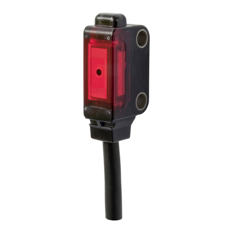
Sensor heads
LS-H91
Coaxial retroreflective
Type
LS-H22 (Note 2)
Long sensing range line reflective
Diffuse reflective
LS-H21
LS-H91F LS-H22F (Note 2)LS-H21F
Long sensing range spot reflective
Item
Material Enclosure: PBT (Polybutylene terephthalate)(Mounting part: PEI), Lens cover: Acrylic
Cable 0.1 mm2, single core two parallel shielded cables, 2 m 6.562 ft long (Connector for amplifier attached)(Note 3)
Weight 30 g approx. 30 g approx.30 g approx.
Ambient temperature 10 to55 C (No dew condensation or icing allowed), Storage: 20 to70 C
Laser emission indicator Green LED (lights up during laser emission)
Spot-size adjuster Multi-turn adjuster
Ambient humidity 35 to 85 % RH, Storage: 35 to 85 % RH
Operation indicator Orange LED (lights up when the amplifier output is ON)
U-LG mode 30 to 1,000 mm 1.181 to 39.370 in0.1 to 7 m 0.328 to 22.966 ft 30 to 1,000 mm 1.181 to 39.370 in
STD mode
FAST mode
H-SP mode
30 to 500 mm 1.181 to 19.685 in0.1 to 5 m 0.328 to 16.404 ft 30 to 500 mm 1.181 to 19.685 in
30 to 300 mm 1.181 to 11.811 in0.1 to 3 m 0.328 to 9.843 ft 30 to 300 mm 1.181 to 11.811 in
Applicable amplifiers LS-400 series
RF-330 (Reflector): 1 pc.
Warning label: 2 pcs. (English 1 pc. and Japanese 1 pc.)
[FDA conforming type: 1 pc. (Based on IEC)]
Warning label: 2 pcs. (English 1 pc. and Japanese 1 pc.)
[FDA conforming type: 1 pc. (Based on IEC)]
LS-MR1 (Lens attachment for line reflective): 1 pc.
Warning label: 2 pcs. (English 1 pc. and Japanese 1 pc.)
[FDA conforming type: 1 pc. (Based on IEC)]
Emitting element Red semiconductor laser, Class 2 (IEC / FDA / JIS)(Max. output: 3 mW, peak emission wavelength: 655 nm 0.026 mil)
Notes: 1) FDA approved devices based on Laser Notice No. 50.
2) LS-H22is the set model No. for LS-H21long distance spot reflective type sensor head combined with the LS-MR1 lens attachment for line reflective.
LS-H21is indicated for the actual product.
3) Cable cannot be extended.
Accessories
Sensing range
Model No.
IEC / JIS standards conforming type
FDA standards conforming type (Note 1)
Amplifiers
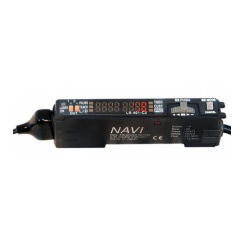
LS-401P
Connector type
LS-401P-C2
Cable type
LS-401 LS-401-C2
Type
PNP output
NPN output
Model No.
Item
Notes: 1) 50 mA if 5 to 8 connector type amplifiers are connected in cascade, and 25 mA if 9 to 16 connector type amplifiers are connected in cascade.
2) The cable is not supplied as an accessory for connector type LS-401(P). Be sure to use the optional quick-connection cables given below.
Main cable (4-core): CN-74-C1 (cable length 1 m 3.281 ft), CN-74-C2 (cable length 2 m 6.562 ft), CN-74-C5 (cable length 5 m 16.404 ft)
Sub cable (2-core): CN-72-C1 (cable length 1 m 3.281 ft), CN-72-C2 (cable length 2 m 6.562 ft), CN-72-C5 (cable length 5 m 16.404 ft)
Power consumption Normal operation: 950 mW or less (Current consumption 40 mA or less at 24 V supply voltage)
ECO mode: 780 mW or less (Current consumption 33 mA or less at 24 V supply voltage)
Digital display
Sensitivity setting
4 digit (green)4 digit (red) LED display
Normal mode: 2-level teaching / Limit teaching / Full auto teaching / Manual adjustment
Window comparator mode: Teaching (1-level, 2-level, 3-level) / Manual adjustment
Hysteresis mode: Teaching (1-level, 2-level, 3-level) / Manual adjustment
Differential mode: 5-level settings
Fine sensitivity adjustment function
Incorporated
Automatic interference prevention function
Incorporated [Up to four sets of sensor heads can be mounted close together (However, disabled when in H-SP mode)]
Ambient temperature
10 to55 C (If 4 to 7 units are mounted close together: 10 to50 C, if 8 to 16 units are mounted close together: 10 to45 C)
(No dew condensation or icing allowed), Storage: 20 to70 C
Ambient humidity 35 to 85 % RH, Storage: 35 to 85 % RH
Material Enclosure: Heat-resistant ABS, Transparent cover: Polycarbonate, Push button switch: Acrylic, Jog switch: ABS
Cable 0.15 mm25-core cabtyre cable, 2 m 6.562 ft long
(Note 2)
Extension up to total 100 m 328.084 ft is possible with 0.3 mm2, or more, cable.
Cable extension
Weight 15 g approx. 65 g approx.
Selectable either Light-ON or Dark-ON, with jog switch
Supply voltage 12 to 24 V DC10 % Ripple P-P 10 % or less
Timer function Incorporated with variable ON-delay / OFF-delay / ONE SHOT timer,
switchable either effective or ineffective. (Timer period: 1 ms to 9,999 ms approx.)
Output
(Output 1, Output 2)
Output operation
Incorporated
Short-circuit protection
<NPN output type>
NPN open-collector transistor
•Maximum sink current: 100 mA (Note 1)
•
Applied voltage: 30 V DC or less (between output and 0 V)
•
Residual voltage: 1.5 V or less [at 100 mA (Note 1) sink current]
<PNP output type>
PNP open-collector transistor
•Maximum source current: 100 mA (Note 1)
•
Applied voltage: 30 V DC or less (between output and V)
•
Residual voltage: 1.5 V or less [at 100 mA (Note 1) source current]
Response time 80 !s or less (H-SP), 150 !s or less (FAST), 500 !s or less (STD), 4 ms or less (U-LG) selectable with jog switch
<NPN output type>
NPN non-contact input
•Signal condition
High: 5V to V DC or open, Low: 0 to 2 V DC (sink current 0.5 mA)
•
Input impedance: 10 k approx.
<PNP output type>
PNP non-contact input
•Signal condition
High: 4V to V DC (source current 3 mA or less), Low: 0 to 0.6 V DC or open
•
Input impedance: 10 k approx.
External input
( )
Laser emission halt
Full-auto teaching / Limit teaching
AUDIN
-
8,
avenue
de
la
malle
-
51370
Saint
Brice
Courcelles
-
Tel
:
03.26.04.20.21
-
Fax
:
03.26.04.28.20
-
Web
:
http:
www.audin.fr
-
Email
:
[email protected]