PRINTED IN JAPAN
Overseas Sales Dept. (Head Office)
2431-1 Ushiyama-cho, Kasugai-shi, Aichi, 486-0901, Japan
Phone: +81-568-33-7861 FAX: +81-568-33-8591
Europe Headquarter: Panasonic Electric Works Europe AG
Rudolf-Diesel-Ring 2, D-83607 Holzkirchen, Germany
Phone: +49-8024-648-0
US Headquarter: Panasonic Electric Works Corporation of America
629 Central Avenue New Providence, New Jersey 07974 USA
Phone: +1-908-464-3550
URL : sunx.com
SUNX Limited
CAUTIONS
14
This product has been developed / produced for industrial use only.
Use within the rated pressure range.
Make sure that the power supply is OFF while wiring.
Take care that wrong wiring will damage the sensor.
Verify that the supply voltage variation is within the rating.
If power is supplied from a commercial switching regulator, ensure that the frame
ground (F.G.) terminal of the power supply is connected to an actual ground.
In case noise generating equipment (switching regulator, inverter motor,
etc.) is used in the vicinity of this sensor, connect the frame ground (F.G.)
terminal of the equipment to an actual ground.
Do not use during the initial transient time (0.5 sec.) after the power supply is switched ON.
Do not run the wires together with high-voltage lines or power lines or put
them in the same raceway. This can cause malfunction due to induction.
7KHVSHFL¿FDWLRQPD\QRWEHVDWLV¿HGLQDVWURQJPDJQHWLF¿HOG
Extension up to total 100m is possible with 0.3mm2, or more, cable.
Avoid dust, dirt, and steam.
Take care that the product does not come in contact with water, oil,
grease, or organic solvents, such as, thinner, etc.
Do not operate the keys with pointed or sharp objects.
Make sure that stress by forcible bend or pulling is not applied directly to the sensor cable joint.
Ɣ
Ɣ
Ɣ
Ɣ
Ɣ
Ɣ
Ɣ
Ɣ
Ɣ
Ɣ
Ɣ
Ɣ
Ɣ
Ɣ
Ɣ
Notes: 1)
The cable with connector is not enclosed with models that have “-J” at the end of the model names.
2)
Excluding the current consumption of analogue current output and applying pressure sensor head.
3)
The values specified above are applied only to the controller. Regarding the
VSHFL¿FDWLRQVIRUWKHDSSOLHGSUHVVXUHVHQVRUKHDGUHIHUWRWKHLQVWUXFWLRQPDQXDO
enclosed with the pressure sensor head.
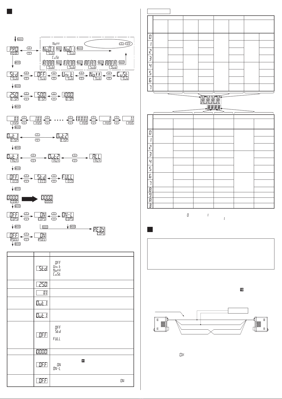
SPECIFICATIONS
16
Type NPN output type PNP output type
For use inside Japan
For use outside Japan
For use inside Japan
For use outside Japan
Item
Model No.
(Note 1) DPC-101Z DPC-101 DPC-101Z-P DPC-101-P
Applicable pressure
sensor head
Compound pressure type DPH-101Ƒ3RVLWLYHSUHVVXUHW\SHDPH-102Ƒ
Vacuum pressure type DPH-103Ƒ
Rated pressure range
0 to -101.0kPa / 0 to 1.000MPa / -100.0 to 100.0kPa
Set pressure range
101.3 to -101.3kPa / -1.050 to 1.050MPa / -199.9 to 199.9kPa
Supply voltage 12 to 24V DC ±10% Ripple P-P 10% or less
Power consumption
(Note 2)
Normal operation: 960mW or less (current consumption 40mA or less at 24V supply voltage)
ECO mode (STD): 720mW or less (current consumption 30mA or less at 24V supply voltage)
ECO mode (FULL): 600mW or less (current consumption 25mA or less at 24V supply voltage)
Sensor head supply voltage
Same as supply voltage
Input
Pressure sensor head input
Input voltage range: 1 to 5V DC (within the rated pressure range)
External input
ON voltage: 0.4V DC or less
OFF voltage: 5 to 30V DC or open
,QSXWLPSHGDQFH$SSUR[Nȍ
Input time: 1ms or more
•
•
•
•
ON voltage: 5V to +V DC
OFF voltage: 0.6V DC or less or open
,QSXWLPSHGDQFH$SSUR[N
Input time: 1ms or more
•
•
•
•
Comparative output
(Comparative output 1/2)
NPN open-collector transistor
Maximum sink current: 100mA
Applied voltage: 30V DC or less
(between comparative output and 0V)
Residual voltage: 1V or less
(at 100mA sink current )
•
•
•
PNP open-collector transistor
Maximum source current: 100mA
Applied voltage: 30V DC or less
(between comparative output and +V)
Residual voltage: 1V or less
(at 100mA source current )
•
•
•
Output operation Selectable either NO or NC, with key operation
Hysteresis
Min. 1 digit (however, 2 digits when using psi units for use outside Japan)
Repeatability
With positive / vacuum pressure type connected: Within ±0.2% F.S. digit (±2 digits)
With compound pressure type connected: Within ±0.2% F.S. digits (±4 digits)
Response time
0.5ms, 1ms, 2.5ms, 5ms, 10ms, 25ms, 50ms, 100ms, 250ms,
500ms,
1,000ms or 5,000ms selectable with key operations
Analogue output
$QDORJXHYROWDJHRXWSXW!
Output voltage: 1 to 5V
2XWSXWLPSHGDQFHDSSUR[N
Zero point:
Within 1V ±0.5% F.S.
(positive / vacuum pressure)
Within 3V ±0.5% F.S.
(compound pressure)
Span: Within 4V ±0.5% F.S.
Linearity: Within ±0.1%F.S.
•
•
•
•
•
$QDORJXHFXUUHQWRXWSXW!
Output current: 4 to 20mA
/RDGUHVLVWDQFHȍ0$;
Zero point:
Within 4mA ±1%F.S.
(positive / vacuum pressure)
Within 12mA ±1.5%F.S.
(compound pressure)
Span: Within 16mA ±1.5%F.S.
Linearity: Within ±0.1%F.S.
•
•
•
•
•
Ambient temperature
-10 to +50°C (No dew condensation or icing allowed), Storage: -10 to +60ºC
Ambient humidity WR5+6WRUDJHWR5+
Temperature characteristics
Within ±0.5% F.S. (at +20ºC reference)
Material (QFORVXUH3%7ZLWKJODVV¿EHU/&'GLVSOD\$FU\OLF
Mounting screw section: Brass (nickel-plated), Key: Silicone rubber
Weight Approx. 25g (Main body only)
Accessory
CN-66A-C2 (Cable with a connector, 2m long) (optional for Jtype)
Unit switching label: 1 pc.
ERROR INDICATION
15
Error
indication
Cause Remedy
The controller and the pres-
sure sensor head are not cor-
rectly connected.
The pressure sensor head is
damaged.
•
•
Connect the controller and the pres-
sure sensor head correctly.
Replace the pressure sensor head.
•
•
The load is short-circuited caus-
LQJDQRYHUFXUUHQWWRÀRZ
Turn the power OFF and check the
load.
Pressure is applied during zero-
point adjustment.
Applied pressure at the pressure port should
be brought to atmospheric pressure and
zero-point adjustment should be done again.
External input is carried out out-
side the rated pressure range.
Applied pressure range should be
brought within the rated pressure range.
Communication error
(Disconnection, faulty connection, etc.)
Check the wiring when using the copy
function.
Communication error
(Incorrect model.)
0DNHVXUHWKDWWKHV\VWHPLVFRQ¿JXUHGRIWKH
same models when using the copy function.
The applied pressure exceeds the up-
per limit of the display pressure range.
Applied pressure range should be
brought within the rated pressure range.
The applied pressure exceeds the low-
er limit of the display pressure range.
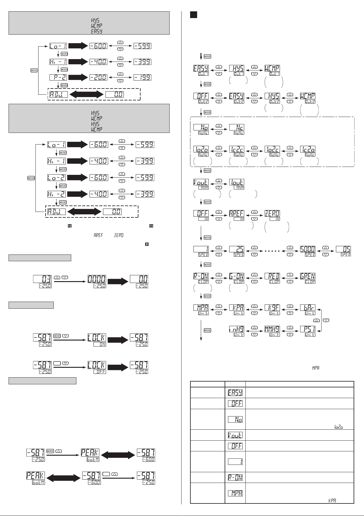
REMOTE ZERO-ADJUSTMENT FUNCTION
13
The setting value is not corrected when remote zero-adjustment is input-
ted. Make sure that the pressure and set value during remote zero-adjust-
ment do not exceed the set pressure range.
Notes: 1)
The setting values shift in the same manner during the EASY mode or the window comparator mode.
2) The remote zero-adjustment function is applicable only to the comparative output
set at the external input relation selection. Unset comparative output operates
based on the atmospheric pressure.
The remote zero-adjustment function forcibly sets the pressure value to
“zero” when the external signal is inputted.
Ɣ
Operation chart
0 102030405060
01020
12
10 20
30 40 50 60
0 102030405060
㧙10
010
1
10
20
2
20
30 40 50
During remote zero-adjustment input
(each comparative output set to N.O.)
•
Detected pressure at remote zero-adjustment input: 10kPa
• Output mode: Hysteresis mode
Output
Applied pressure (kPa)
Displayed value (kPa)
Set value (kPa)
ON
OFF Output
Applied pressure (kPa)
Displayed value (kPa)
Set value (kPa)
ON
OFF
During normal operation
(each comparative output set to N.O.)
The remote zero-adjustment value is cleared when the setting of the ex-
ternal input selection function is changed or the power is turned ON again,
and normal operation based on the atmospheric pressure is resumed.
The remote zero-adjustment value can be confirmed when setting the
threshold value in RUN mode. Refer to the threshold value setting in “
RUN MODE” for the details.
Ɣ
Ɣ
If the corrected set value exceeds the set pressure range when auto-reference
input is carried out, the set value will be automatically corrected to within the
set pressure range. Thus, take care not to exceed the set pressure range.
Note:
The set values shift in the same manner during the EASY mode or the window comparator mode.
AUTO-REFERENCE FUNCTION
12
The auto-reference function corrects
the set value using the detected
pressure value during auto-reference
input as the reference pressure.
Using the detected pressure value at
auto-reference input P(a) as a refer-
ence, the set value 1’ is automatically
corrected to “set value 1+ P(a).”
Ɣ
Ɣ
Before auto-
reference
ON
ON
OFF
OFF
tmospheric pressure
Pressure
Set value 1
P(a)
Set value 1’
After auto-
reference
Set value 1’ after auto-reference is:
1’ = 1+ P(a)
Detected pressure value
at auto-reference input
6HWWDEOHUDQJHDQGVHWSUHVVXUHUDQJHDIWHUFRUUHFWLRQ
The setting pressure range is wider than the rating pressure range so that
the auto-reference function can be handled.
Ɣ
Operation chart
Output
0 102030405060
01020
12
10 20
30 40 50 60
Applied pressure (kPa)
Displayed value (kPa)
Set value (kPa)
ON
OFF Output
Applied pressure (kPa)
Displayed value (kPa)
Set value (kPa)
ON
OFF
0 102030405060
01020
P (a) 1’
10 20
30
2’
30
40 50 60
During auto-reference input
(each comparative output set to N.O.)
During normal operation
(each comparative output set to N.O.)
•
Detected pressure at auto-reference input: 10kPa
• Output mode: Hysteresis mode
The detected pressure value at auto-reference input becomes “zero”
when the setting of the external input selection function is changed or
the power is turned ON again.
The auto-reference input value can be checked when setting the threshold value
in RUN mode. Refer to the threshold value setting in “ RUN MODE” for details.
Ɣ
Ɣ
INTENDED PRODUCTS FOR CE MARKING
17
The models listed under “ SPECIFICATIONS” come with
CE Marking.
$VIRUDOORWKHUPRGHOVSOHDVHFRQWDFWRXURI¿FH
Ɣ