2
Diagram of Functions and Settings
2-1. Diagram of Functions and Settings
2
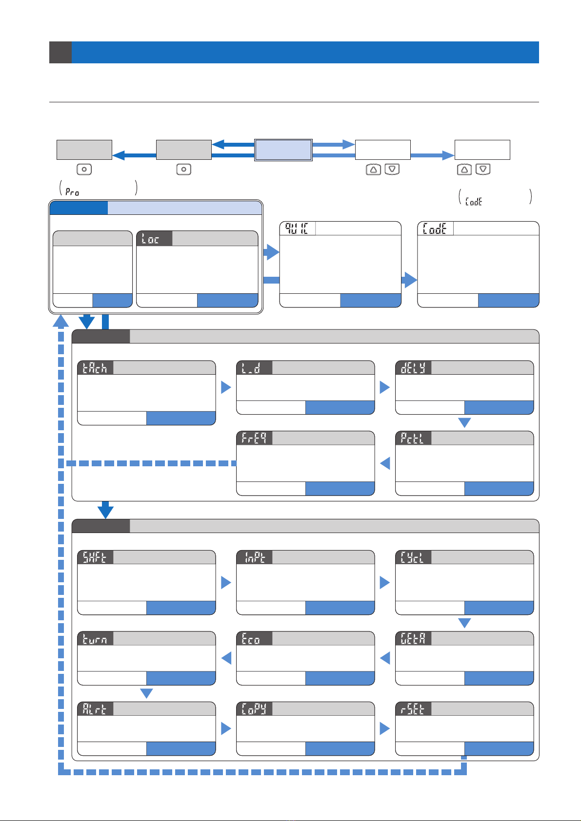
The amplifier features and settings can be generally classified into three main modes: the ‘RUN mode’ for normal
sensing operation, the ‘SET mode’ for basic settings, and the ‘PRO mode’ that contains more detailed settings.
This mode is used for carrying out basic settings.
SET Mode P. 5
Press for 4 sec.
during RUN mode.
Press for 2 sec.
during RUN mode.
Keep pressing until
‘ ’ is displayed. Keep pressing until
‘ ’ is displayed.
Press simultaneously
for 2 sec. during
RUN mode.
Press simultaneously
for 4 sec. during
RUN mode.
RUN Mode QUIC CODESET ModePRO Mode
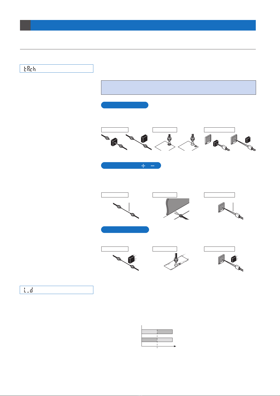
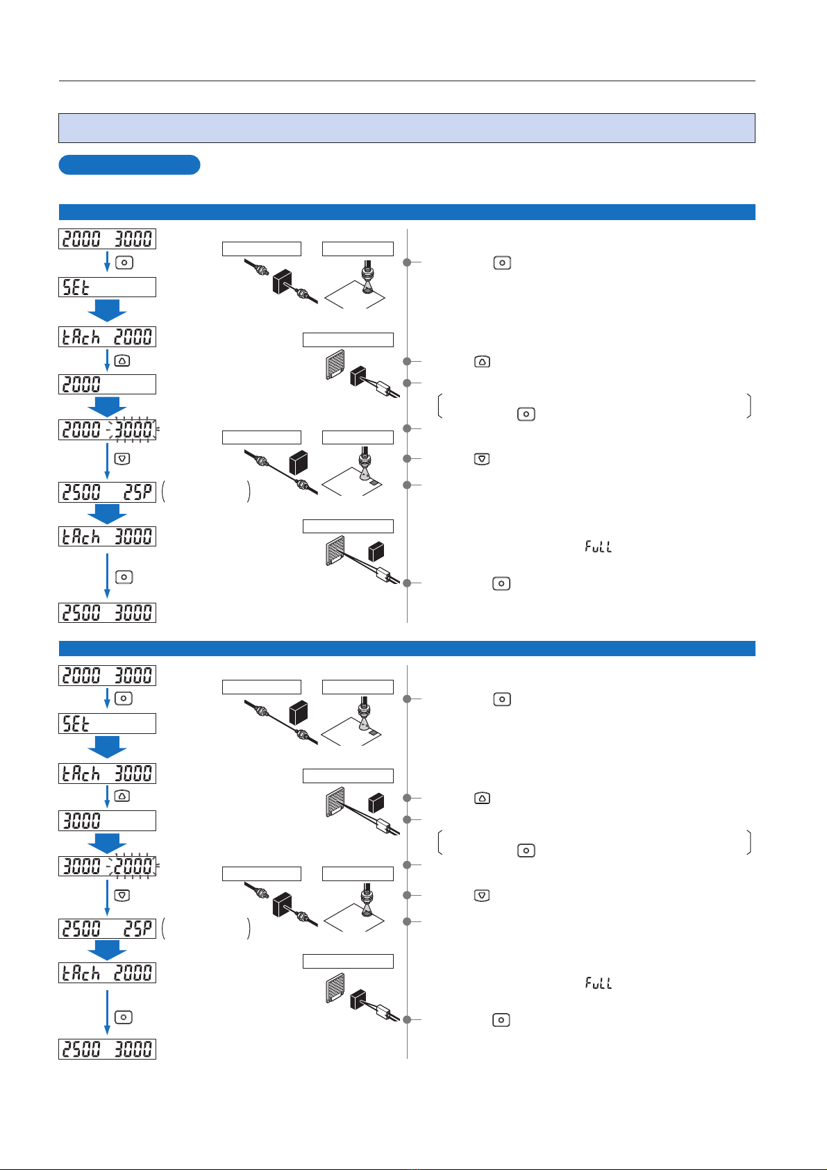
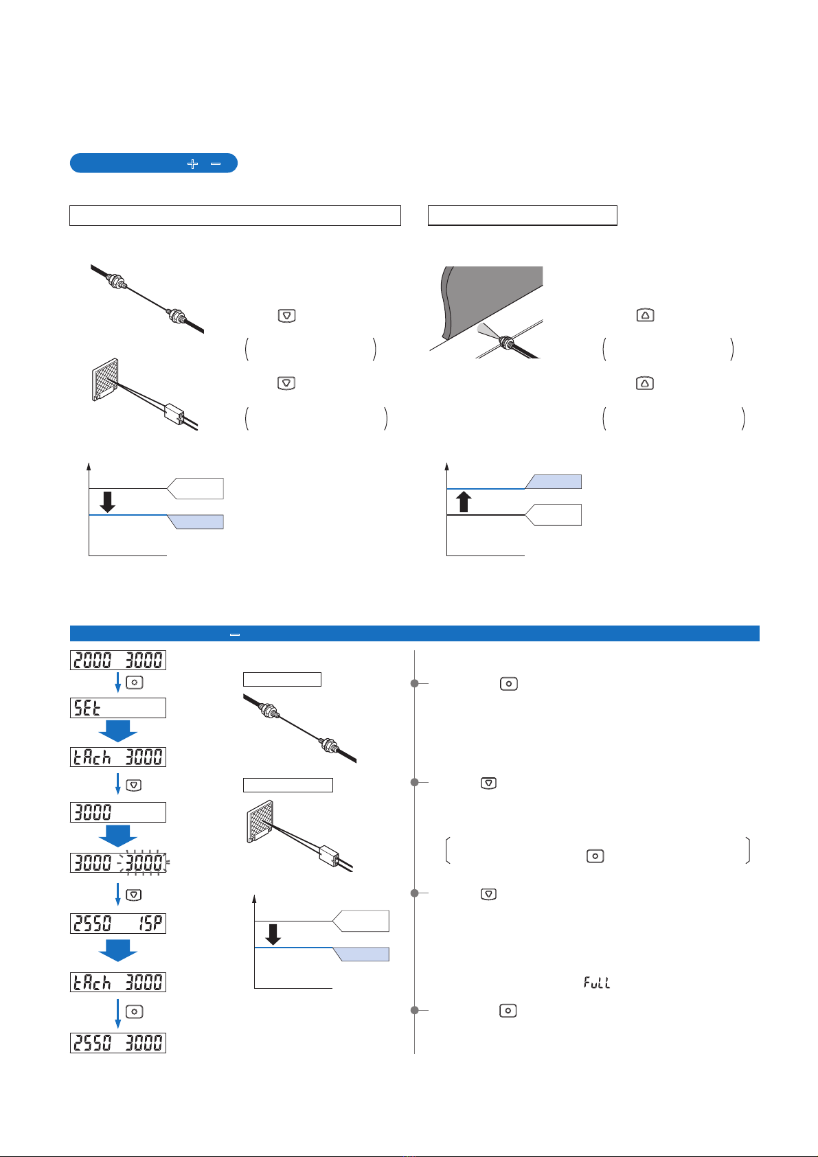
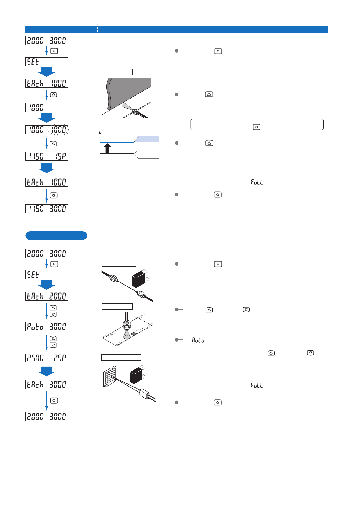
Threshold value can be set in 2-level
teaching, limit teaching [,], or
full-auto teaching.
Teaching
Procedure: P.7lDetails: P.5
Light-ON or Dark-ON can be set.
Output Operation Setting
Procedure: P.10Details: P.5
Configures timer operation and timer
period.
Timer Operation Setting
Procedure: P.10Details: P.6
When fiber heads are used side-by-side,
the emission frequencies for each amplifier
can be set to different emission frequencies
in order to prevent interference.
Emission Frequency Setting
Procedure: P.12Details: P.6
Allows light reduction to be set for the
light-emitting amount. This is useful if
sensing is difficult because the
incident light intensity is saturated.
Light-emitting Amount Selection Setting
Procedure: P.11Details: P.6
This mode is used for carrying out detailed settings.
PRO Mode P. 1 3
Allows the shift amount for limit
teaching [,] and for threshold
value follow-up cycle setting to be set
within the range of 0 to 80 %.
Shift Setting
Procedure: P.18Details: P.13
External input can be selected from
emission halt, limit teaching [], limit
teaching [], full-auto teaching, and
ECO.
External Input Setting
Procedure: P.18Details: P.13l
Allows follow-up of the threshold value to
be carried out within a set range (shift
amount) in response to fluctuations in the
incident light intensity.
Threshold Value Follow-up Cycle Setting
Procedure: P.19Details: P.15
Allows the viewing orientation of the digital
display to be inverted in accordance with
the setting direction of the amplifier.
Digital Display Inversion Setting
Procedure: P.22Details: P.17
Sets the digital display to turn off in
order to reduce power consumption
(current consumption).
ECO Setting
Procedure: P.21Details: P.17
Allows the display value for the
incident light intensity to be offset by
the desired value (target value).
GETA
Function
Setting
Procedure: P.20Details: P.16
Margin for threshold value to the
present incident light intensity can be
checked.
Threshold Value Margin Setting
Procedure: P.22Details: P.17
The settings of the master side
amplifier can be copied to the slave
side amplifier.
Setting Copy
Procedure: P.23Details: P.17
Allows all settings to be returned to
the factory settings.
Reset
Procedure: P.24Details: P.17
This indicates normal sensing operation.
RUN Mode
Fine adjustment of
the threshold value
can be done when in
RUN mode.
Threshold value fine
adjustment function
P. 4
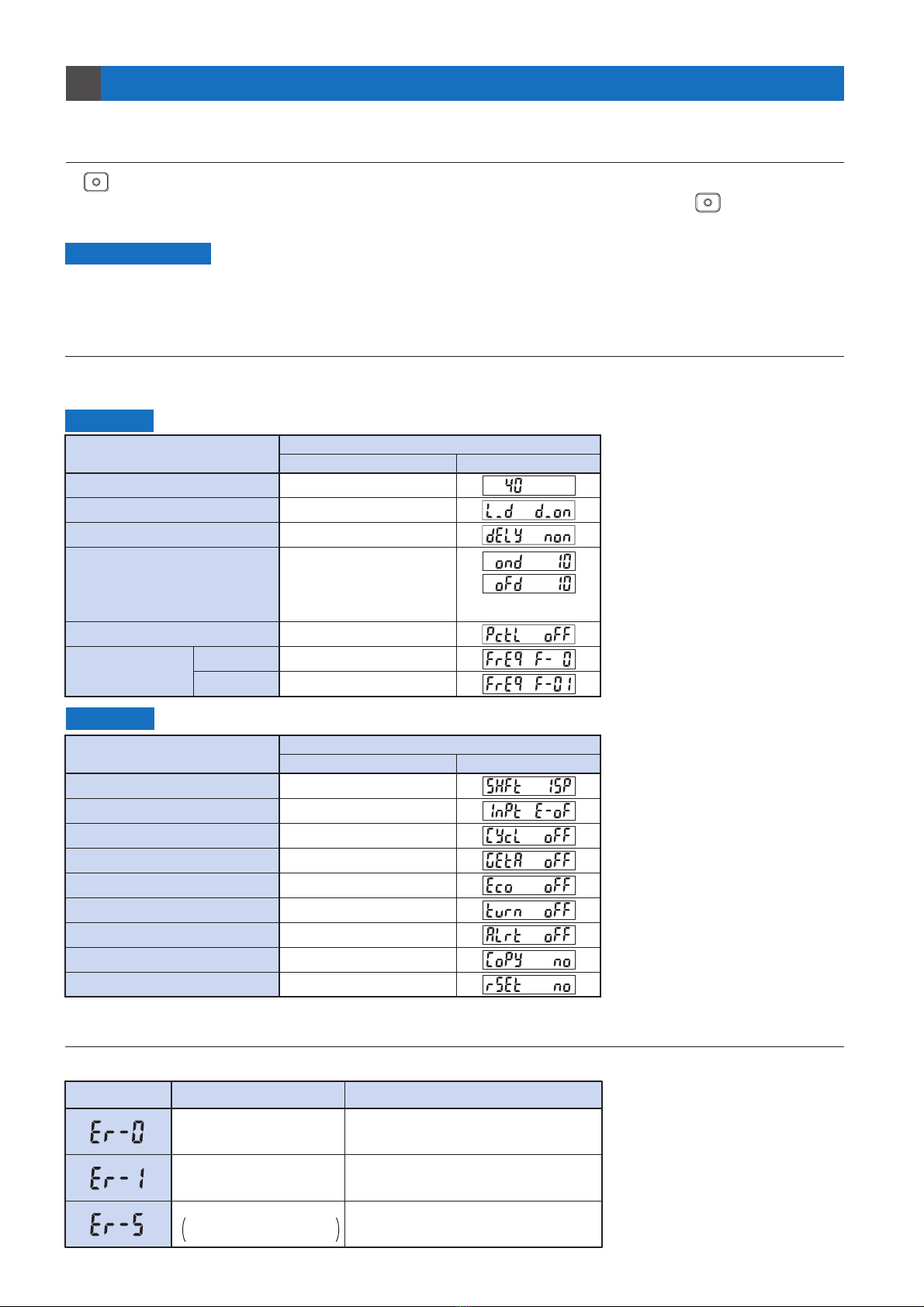
Allows various settings (output
operation settings, timer operation
settings, light-emitting amount selection
settings and emission frequency
settings) to be made in SET mode
simply by selecting a setting number.
Quick Setting Function
Procedure: P.25Details: P.25
Settings for output operation, timer
operation, light-emitting amount
selection, emission frequency,
ECO, external input, and shift
amount are possible by selecting
codes discretionary.
Code Setting Function
Procedure: P.26Details: P.26
The key lock function prevents
key operations so that the
conditions set in each setting
mode are not inadvertently
changed.
Key Lock Function
Procedure: P.4Details: P.4
Procedure: P.4
Details: P.4