SWIT M-1093H User manual

1
Model: M-1093H
9” Full HD Rack Mount LCD Monitor
User Manual
Ver:A
SWIT Electronics Co., Ltd.
Please read this User Manual
throughout before using.

2
Preface
1. All internal technologies of this product are protected, including device, software and trademark.
Reproduction in whole or in part without written permission is prohibited.
2. All brands and trademarks of SWIT Electronics Co., Ltd. are protected and other relative
trademarks in this user manual are the property of their respective owners.
3. Due to constant effort of product development, SWIT reserves the right to make changes and
improvements to the product described in this manual without prior notice.
4. The warranty period of this product is 2 years, and does not cover the following:
(1) Physical damage to the surface of the products, including scratches, cracks or other damage to
the LCD screen or other externally exposed parts;
(2) The LCD dot defects are not over three;
(3)Any damage caused by using third-party power adaptors;
(4) Any damage or breakdown caused by use, maintenance or storage not according to the user
manual.
(5) The product is disassembled by anyone other than an authorized service center.
(6) Any damage or breakdown not caused by the product design, workmanship, or manufacturing
quality, etc.
*Any sales personnel have no rights to provide additional warranty.
5. For any suggestion and requirement on this product, please contact us through phone, fax, Email,
etc.
SWIT Electronics Co., Ltd.
Address: 10 Hengtong Road, Nanjing Economic and Technological Development Zone,
Nanjing 210038, P.R.China
Phone: +86-25-85805753
Fax: +86-25-85805296
Email: cont[email protected]
Website: http://www.swit.cc

3
Maintenance
Warning
1. In order to reduce the risk of fire and electrical shock, do not lay this product in rain or damp
places.
2. Please keep away from the strong magnetic field; it may cause the noise of the video and audio
signals.
The power
1. Please use the power adapter provided or recommended by the manufacturer in order to avoid
damage.
2. For a third party power adapter, please make sure the voltage range, supplied power, and
polarity of power lead are fit.
3. Please disconnect the power cable under the following situations:
(A). If you do not operate this monitor for a period of time;
(B). If the power cable or power adaptor is damaged;
(C). If the monitor housing is broken.
The monitor
1. Please don't touch the screen with your fingers, which would probably deface the screen.
2. Please don't press the screen; the LCD is extremely exquisite and flimsy.
3. Please don't lay this product on unstable place.
Cleaning
1. Please clean the screen with dry and downy cloth or special LCD cleanser.
2. Please do not press hard when cleaning the screen.
3. Please do not use water or other chemical cleanser to clean the screen. The chemical may
damage the LCD.

4
Contents
Preface.....................................................................................................................................................2
Maintenance............................................................................................................................................3
Contents...................................................................................................................................................4
Packing list...............................................................................................................................................4
Introduction..............................................................................................................................................4
Installation Dimensions............................................................................................................................5
Operation Instructions .............................................................................................................................6
Front Panel...........................................................................................................................................6
OSD......................................................................................................................................................7
Back Panel...........................................................................................................................................9
Main Menu.............................................................................................................................................10
Specification...........................................................................................................................................16
Trouble-Shooting...................................................................................................................................17
Packing list
Standard Package:
1. User Manual
2. Warranty Card
3. LCD protective film
4. Power cable
Introduction
M-1093H adopts IPS LCD panel, with resolution 1920×1200 and wide viewing angle H170°∕V170°. It
supports 2 x 3GSDI (Level A/B), 1 x HDMI, 1 x CVBS and 1 x analog audio input. It also supports 2 x
3GSDI, 1 x HDMI, 1 x CVBS and 1 x analog audio loop through output.
Features:
Support multipleAspect Ratio and scan modes
Support multiple Marker selection (Marker, SafetyArea)
Support multiple functions user-defined (Source ID, function keys, GPI)
Multiple power supply methods to meet different requirements
TSL UMD(RS485)Tally, GPI control
USB firmware upgrade
Support 2K

5
Installation Dimension
The main body (in mm):

6
Operation Instructions
·Front Panel
⑴Speaker: For SDI/HDMI embedded audio and analog audio monitoring. (Will not work if earphone
is plugged in)
⑵Button
SOURCE: Press “SOURCE” to select SDI1, SDI2, HDMI, and CVBS signal input.
F1~F5: User definable function keys. Please see details in “4. Function key” under “Main Menu”.
For example: Set F1 to “Histogram”. Press F1 to open histogram and press again to close.
AUDIOBAR: Press “AUDIOBAR” to switch on/off audio bar.
DISPLAY: Press “DISPLAY” to turn on or turn off relevant status information, audio and video
waveform.
When main menu is activated, press “DISPLAY” to quit menu.
⑶Rotary Knob
MENU/ENTER: When the menu is inactivated, presses “MENU/ENTE” to turn on the main menu;
Revolve “MENU/ENTER” to adjust settings or parameters, and press to apply;
When the menu is inactivated, revolve “MENU/ENTER” to adjust sound volume.
BRIGHT: 0-100 value adjustment and the default value is 50.
CONTRAST: 0-100 value adjustment and the default value is 50
SATURATION: 0-100 value adjustment and the default value is 50
⑷POWER: Power on/off
⑸TALLY Light: Red, Green and Yellow 3-color TALLY indicator

7
·OSD
⑴Time code(SDI)
Under SDI input, it can display Time code. If no Time code information is detected, it will be
displayed as “TC: UNLOCKED”.
User can set function keys F1~F5 or GPI pins as “Time code” to turn on or off this function.
⑵UMD
Set up the UMD under ‘UMD” submenu.
⑶AFD (SDI)
User can set function keys F1~F5 or GPI pins as “AFD” to turn on or off this function. If no
relevant information is detected, it will be displayed as “AFD: UNLOCKED”.
⑷Audio
Monitor the audio information. User can set function keys F1~F5 or GPI pins as “Audio” to turn
on or off this function.
The relevant parameters like position, audio channels and blending, etc can be changed under
“Audio” submenu.

8
Introduction of audio and video functions
2-ch embedded audio meters
Under 3G/HD/SD SDI, HDMI and CVBS, it displays 2 channels embedded audio meters. The
audio meter is green, and will turn yellow when audio exceeds -20dB, and turn red when audio
exceeds -9dB.
Audio alarm
If the embedded audio value is too low or no embedded audio, it will display “MUTE” or
“UNLOCKED” in the audio bar.
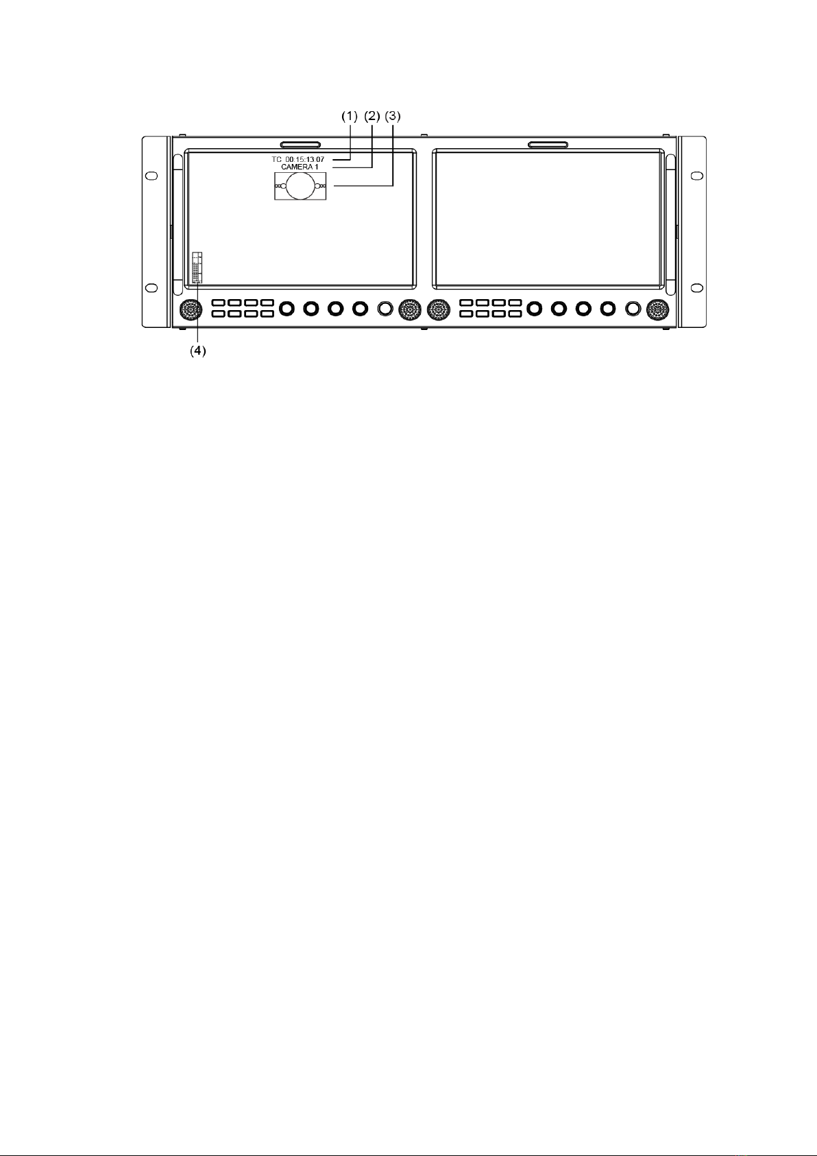
Time code (SDI)
Under SDI input, it can display the SMPTE time code (VITC1, VITC2 or LTC) on the top of the
screen, which is used extensively for synchronization, and for logging and identifying material in
recorded media. If no Time code information is detected, it will be displayed as “UNLOCKED”.
Internal Color Bar
Under SDI and HDMI input, it has 100% internal color bar which helps to analyze the monitor color
and adjust the display parameter.
User can set function Keys F1~F5 or GPI pins as “color bar” to turn on or off this function.
Peaking focus assist (red/blue switch)
The Peaking focus assist function is to mark the sharpest edges of the image with red or blue
color under SDI and HDMI input, for users to check if the subjects are focused.
User can set function Keys F1~F5 or GPI pins as “FocusAssist” to turn on or off this function.
Zebra stripes
Zebra Stripes are used to check if the image is over exposed or not by showing black and white
lines on the monitor. It is considered over exposed when luminance value exceeds 90%.
User can set function Keys F1~F5 or GPI pins as “Zebra” to turn on or off this function.
Freeze Frame
The freeze frame is to capture and display the current broadcast frame.
User can set function Keys F1~F5 or GPI pins as “Freeze Frame” to turn on or off this function.
R/G/B/Mono
R/G/B/Mono is to display only the blue/red/green primary signal or the luminance signal only so as
to monitor the image noise.
User can set function Keys F1~F5 or GPI pins as “R/G/B/Mono” to turn on or off this function.
False Color
The false color is used to aid in the setting of camera exposure. Under false color mode, there’s a
color chart on the bottom of screen for reference. The color from the dark to the bright will be
displayed as blue, cyan, green, yellow, orange and red in a consecutive way. User can set
function Keys F1~F5 or GPI pins as “False color” to turn on or off this function.
AFD (SDI)
It is the abbreviation of active format description. AFD is to display the SDI embedded AFD
information graphically on the screen.
H/V Delay (SDI)
Under SDI input, H/V Delay can be used to display line/field blanking signal, and to observe the
horizontal and vertical synchronous signal.
UMD
When using external control unit, it can display the video source ID and tally information on the
screen.
Image Flip
Horizontal, vertical, horizontal and vertical two-way image flip function.

9
·Back Panel
⑴GPI: TSL UMD&GPI control socket
⑵SDI-LOOP1: SDI loop through output from SDI-IN1 (BNC connector)
⑶SDI-LOOP2: SDI loop through output from SDI-IN2 (BNC connector)
⑷CVBS-OUT: CVBS output (BNC connector)
⑸HDMI socket
HDMI-IN: HDMI input (HDMI-A connector)
HDMI-OUT: HDMI loop through output from HDMI-IN (HDMI-A connector)
⑹AUDIO IN: 3.5mm analog audio input (CVBS)
⑺AUDIO OUT: 3.5mm audio output, to monitor SDI embedded audio, HDMI and analog audio output
⑻DC 12V IN: Connect with DC12V 4-pin XLR power adapter, support 6.5V-24V voltage input (Pin 1:
Negative, Pin 4: Positive)
⑼CVBS-IN: CVBS input (BNC connector)
⑽SDI-IN2: SDI input (BNC connector)
⑾SDI-IN1: SDI input (BNC connector)
⑿USB socket
⒀Power adaptor

10
Main Menu
M-1093H has OSD to adjust the parameters and settings, for example: Picture, Color Temp.,
Function Key, etc.
1. Press “MENU/ENTER” button, the main menu will popup from the left top of the screen. The
selected main menu highlights in yellow.
2. Revolve “MENU/ENTER” to select submenu, the selected submenu highlights in yellow, press
“MENU/ENTER” to apply and enter into the selected submenu’s items.
3. Revolve “MENU/ENTER” to select the item which needed to be adjusted, press “MENU/ENTER”,
the selected item and its parameters will be highlighted in yellow.
4. Revolve “MENU/ENTER” to change the selected item’s parameter, press “MENU/ENTER” to apply
and save the settings.
5. Revolve “MENU/ENTER” to select “Exit”, press “MENU/ENTER” to quit submenu. Select “Exit &
Status” under the Main Menu and press to quit Main Menu.
Notice:
*The items in gray can not be set up.
*If there is no operation under the setted time, the menu will automatically save settings and quit.
*If the key inhabit function is turned on, except key inhibit function, all other items are in grey. Please
turn off the key inhibit function to adjust the items.

11
Submenu introduction(the default values are marked with underline )
1. Exit & Status
Displays the current status, the details are as down below:
*1 Display the current video signal and format
*2 Display the current function keys setup
2. Picture
To adjust picture parameters
3. Color Temp
To select different color temperature or setup user-defined color parameters.
* Only “Color Temp” is set to “User”, the Red/Blue/Green Gain or Red/Blue/Green Bias can be
adjusted.
4. Function Key
To define the F1~F5 function keys.
*1 Function keys F1-F5 can be setted as the down below functions:
Time code, Zebra, Audio Bar, False Color, AFD, H/V Delay, R/G/B/Mono, Marker , Color Bar, UMD,

12
Audio Alarm, Focus Assist , Aspect Ratio, Scan Mode, Zoom Mode, Mute, Freeze Frame, Flip Mode,
CVBS,HDMI, SDI1,SDI2, Color Temp.
For example: Set F3 to “R/G/B/Mono” under “Function key” submenu. User can press F3 on the
front panel to adjust the parameters of “R/G/B/Mono”, and the “R/G/B/Mono” will change and follow the
sequence: Blue Only →Red Only →Green Only →Mono →Off.
5. GPI
User can set GPI pins1~4 to relevant functions to turn on or off this function.
*1 When “GPI control” is set to “On”, the monitor can be operated through external GPI control unit.
*2 The GPI pins can be setted to the down below functions:
Red Tally, Green Tally, Yellow Tally, Aspect Ratio, Scan Mode, Zoom Mode, Mute, Freeze Frame,
Flip Mode, Color Temp, Time code, Zebra, Audio Bar, False Color, AFD, H/V Delay, R/G/B/Mono,
Marker, Color Bar, UMD,Audio Alarm, Focus Assist.
When connecting the GPI pin with ground, the setted function will be turned on, and goes out
when disconnecting.
Example 1: Under “GPI ” submenu, set “GPI control” to “On”, set “2 Pin” to “Red Tally”, when the
pin 2 of the extenal GPI control unit is connected with ground, the Tally light on the front panel will turn
red. When disconnected, the tally light will turn off.
Example 2: Under “GPI ” submenu, set “GPI control” to “On”, set “4 Pin” to “Scan Mode”, when the
pin 4 of the extenal GPI control unit is connected with ground, the Scan mode will change and follow
the sequence: “Normal” →”Overscan”→”Native” .
6. UMD
Support “TSL UMD Protocol-V3.1/V4.0” provided by Television System LTD
Setup Source ID:
Select “Source ID”, revolve “MENU/ENTER” to select the letters and press “MENU/ENTER" to
input. Max 8 letters are supported. Select “Exit” to quit and save settings, the source ID will be
displayed on top or bottom of the screen.

13
UMD setup:
⑴Connect the external control equipment with M-1093H;
⑵Set “Display Type” to “UMD” under UMD submenu;
⑶Make sure the “address”, “Baud Rate”, “Parity” the same;
⑷Adjust the external control equipment and send UMD command, the UMD information will be
display as the right photo.
User can set the character and color of the UMD and the color of Tally1 and Tally2.
Please see “5. GPI” to check the”RS485 pin sequence and definition.
7. Marker
*1 When “Fit Marker” is “Off”, the size of safety area is benchmarked against the actual display screen,
accounting for 80% ~ 95% of actual display screen. When “Fit Marker” is “On”, the size of safety area
is benchmarked against the area inside the scales marker, accounting for 80% ~ 95% of the area
inside the scales marker.
Example:
Aspect ratio: 4:3 Aspect ratio: 4:3
SafetyArea: 85% SafetyArea: 85%
Center Marker: On Center Marker: Off
Fit Marker: Off Fit Marker: On

14
8. Audio
*1 When “Bar Frame” is set to “Off”, only the audio meter will be displayed.
When “Bar Frame” is set to “On”, frame and real-time audio value will be displayed.
*2 When “Audio Alarm” is set to “On”, if no embedded audio is detected, the audio bar will display
“UNLOCKED”. If the audio value is too low, the audio bar will display “MUTE”.
*3 Only under SDI I signal, channel1-2 can be selected.
In audio bar, the left channel audio value is marked with green and right channel audio value is
marked with red.
9. Display
10. System

15
*1 Source Scan
When set to “ON”, after turn on the monitor, the signal will be inspected and follow the sequence
of “SDI1→SDI2→HDMI→CVBS”.
For example: if channel is selected to SDI2, SDI-IN2 has no input, and CVBS has input. When
turn on the monitor, after automatic inspection, SDI2 has no recognized signal, and CVBS has
recognized signal, then the input signal will be CVBS.
When set to “Off”, source scan will not be supported.
*2 Logo
When powered on, the screen will display SWIT logo.
*3, *4 Update Driver/ Kernel
⑴Power the monitor, insert the USB equipment with update software into the USB socket.
⑵Press “MENU” to open the main menu, and revolve to “system” submenu,
⑶Set “Update Driver” and “Update Kernel” to “Yes” under “System” Submenu, press
“MENU/ENTER” to apply.
⑷During the update procedure, please do not power off to make sure the software writing has
been successfully completed.
⑸After upgrading, the monitor will auto restart.
11. OSD
12. Key Inhibit
If the “Key Inhibit” is “On”, there is no response when all the buttons expert ” MENU/ENTER” are
pressed, the sreen will be displayed as ” Key Inhibit”.
User can set “Key Inhibit” under “key Inhibit” submenu to “Off” to recover the functions of all
buttons.

16
Specification
LCD Performance
Size
9inch
×
2
Display area
191.5
×
119.7 mm
×
2
Resolution
1920
×
RGB
×
1200
Color
8 bit
Aspect ratio
16:9
∕
4:3
Brightness
450 cd
∕㎡
Contrast
1000:1
Viewing Angle
Horizontal: 170°Vertical: 170°
Input/output
Inpu
t
BNC
×
4
3G/HD/SD-SDI input
BNC
×
2
CVBS input
HDMI
×
2
HDMI input
GPI
×
2
UMD, GPI
×
1
USB
×
2
3.5mm
×
2
analog audio input
Out
put
BNC
×
4
3G/HD/SD-SDI loop through output
BNC
×
2
CVBS loop through output
HDMI
×
2
HDMI loop through output
3.5mm
×
2
SDI/HDMI/analog audio output
Video Format
CVBS
NTSC
/
PAL
HDMI
480i
/
576i
/
480p
/
576p
1080i
(
60
/
59.94
/
50
)
720p(60/59.94/50)
1080p(60/59.94/50/30/29.97/25/24/23.98)
1080psf
(
30
/
29.97
/
25
/
24
/
23.98
)
SDI
SMPTE-425M-A/B
1080p
(
60
/
59.94
/
50
)
SMPTE-274M
1080i
(
60
/
59.94
/
50
)
1080p
(
30
/
29.97
/
25
/
24
/
23.98
)
SMPTE-RP211
1080psf
(
30
/
29.97
/
25
/
24
/
23.98
)
SMPTE-296M
720p
(
60
/
59.94
/
50
)
SMPTE-125M
480i
(
59.94
)
ITU-R BT.656
576i
(
50
)
SMPTE-2048-2
2048
×
1080p
(
23.98
/
24
/
25
/
29.97
/
30
/
50
/
59.94
/
60
)
General
Input voltage
DC: 6.5V
~
24V
Power consumption
36W
Working temperature
0
℃~
+40
℃
Working humidity
10%
~
90%
Storage temperature
﹣
15
℃~﹢
60
℃
Storage humidity
10%
~
90%
Dimensions
484
×
177
×
112.8mm
Net weight (main body)
2.8 kg

17
Trouble-shooting
Symptom Possible Causes Solution
No display
The power is not turned on
Please check if the power is
connected, and then
press ”POWER” button to turn on
the monitor
Unstable power voltage
Reconnect to power supply
BNC or HDMI cable loose
contact or not correctly
connected
Check and correctly connect the
BNC or HDMI cable
The attached battery is no
power
Change battery
Using DIY power supply but
the polarity is reversed Refer to the provided power supply,
reconnect the power.
Image or color
abnormal
Bad contact of BNC or HDMI
cable Change cable
Video signal has Interference Remove the interference source(s)
Improper adjustment of the
color parameters
Adjust the “Recall profile” to
“Default” under “System” submenu
Distortion of the image Reset theAspect ratio
Set to Red/Green/Blue only or
Mono
Turn the Blue only/ Red Only/
Green Only/Mono off under
R/G/B/Mono submenu
Turn on the “FocusAssist”
function Turn off the “Focus Assist” function
Turn on the “False Color”
function
Turn off the “False Color” function
No audio output
Set to Mute Turn off MUTE or revolve
“MENU/ENTER” to adjust the
volume
Bad contact of signal cable Change signal cable
Wrong connection or bad
contact of Audio cable Connect to the correct input socket.

18
Table of contents
Other SWIT Monitor manuals