SWIT M-1093F User manual

1
Model: M-1093F
9” Rack Mount Waveform LCD Monitor
User Manual
Ver: B
Please read this User Manual
throughout before using.

2
Preface
1. All internal technologies of this product are protected, including device, software and trademark.
Reproduction in whole or in part without written permission is prohibited.
2. All brands and trademarks of SWIT Electronics Co., Ltd. are protected and other relative
trademarks in this user manual are the property of their respective owners.
3. Due to constant effort of product development, SWIT reserves the right to make changes and
improvements to the product described in this manual without prior notice.
4. The warranty period of this product is 2 years, and does not cover the following:
(1) Physical damage to the surface of the products, including scratches, cracks or other damage to
the LCD screen or other externally exposed parts;
(2) The LCD dot defects are not over three;
(3) Any damage caused by using third-party power adaptors;
(4) Any damage or breakdown caused by use, maintenance or storage not according to the user
manual.
(5) The product is disassembled by anyone other than an authorized service center.
(6) Any damage or breakdown not caused by the product design, workmanship, or manufacturing
quality, etc.
*Any sales personnel have no rights to provide additional warranty.
5. For any suggestions and requirements on this product, please contact us through phone, fax,
Email, etc.
SWIT Electronics Co., Ltd.
Address: 10 Hengtong Road, Nanjing Economic and Technological Development Zone,
Nanjing 210038, P.R.China
Phone: +86-25-85805753
Fax: +86-25-85805296
Email: contact@swit.cc
Website: http://www.swit.cc

3
Maintenance
Warning
1. In order to reduce the risk of fire and electrical shock, do not lay this product in rain or damp
places.
2. Please keep away from the strong magnetic field; it may cause the noise of the video and audio
signals.
The power
1. Please use the power adapter provided or recommended by the manufacturer in order to avoid
damage.
2. For a third party power adapter, please make sure the voltage range, supplied power, and
polarity of power lead are fit.
3. Please disconnect the power cable under the following situations:
(A). If you do not operate this monitor for a period of time;
(B). If the power cable or power adaptor is damaged;
(C). If the monitor housing is broken.
The monitor
1. Please don't touch the screen with your fingers, which would probably deface the screen.
2. Please don't press the screen; the LCD is extremely exquisite and flimsy.
3. Please don't lay this product on unstable place.
Cleaning
1. Please clean the screen with dry and downy cloth or special LCD cleanser.
2. Please do not press hard when cleaning the screen.
3. Please do not use water or other chemical cleanser to clean the screen. The chemical may
damage the LCD.

4
Contents
Preface .................................................................................................................................................................. 1
Maintenance ......................................................................................................................................................... 3
Contents ................................................................................................................................................................ 4
Packing list ............................................................................................................................................................ 4
Installation Dimension ......................................................................................................................................... 5
Operation Instructions ......................................................................................................................................... 6
·Front Panel .................................................................................................................................................. 6
·OSD .............................................................................................................................................................. 7
Introduction of audio and video functions ................................................................................................. 8
·Rear Panel ................................................................................................................................................... 9
Main Menu........................................................................................................................................................... 10
Sub-Menu ............................................................................................................................................................ 11
Specification ........................................................................................................................................................ 18
Trouble-shooting ................................................................................................................................................ 19
Packing list
1. User Manual
2. Warranty Card
3. LCD protective film
4. Power Cable
5
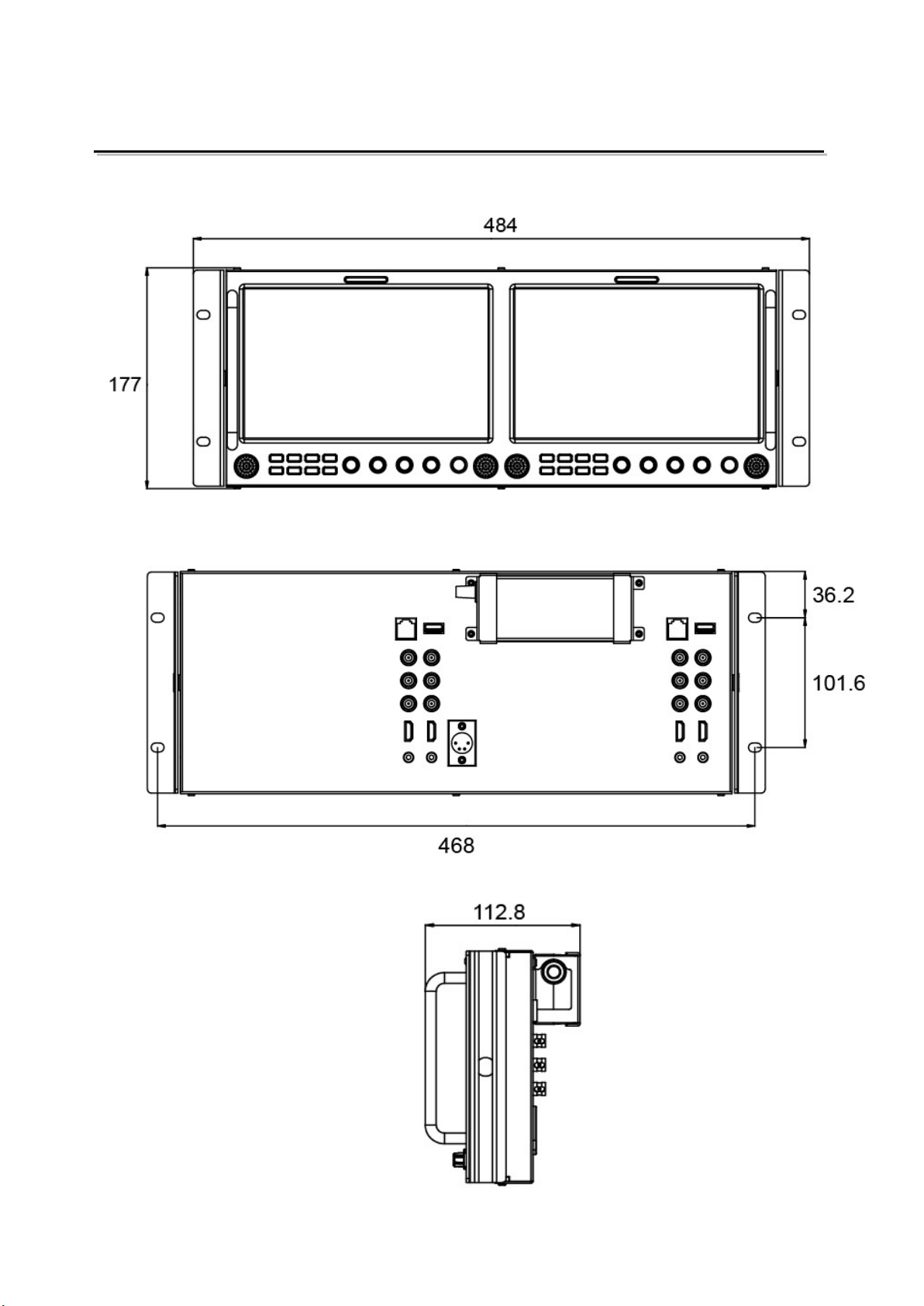
Installation Dimension
The main body (in mm)

6
Operation Instructions
·Front Panel
⑴ Speaker: For SDI/HDMI embedded audio and analog audio monitoring.
(Will not work if headphone socket is plugged in)
⑵ Button
SOURCE: Press “SOURCE” to select SDI1, SDI2, HDMI, and CVBS signal input
F1~F5: User definable function keys. Please see details in “4. Function key” under “Main
Menu”.
WFM: Waveform shortcut key, press “WFM” to quickly turn on or turn off the waveform.
Please setup parameters of waveform under “WFM” submenu.
DISPLAY: Press “DISPLAY” to turn on or turn off relevant status information, audio and
video waveform.
⑶ Rotary Knob
BRIGHT: 0-100 value adjustment and the default value is 50
CONTRAST: 0-100 value adjustment and the default value is 50
SATURATION: 0-100 value adjustment and the default value is 50
MENU/ENTER: When the menu is inactivated, presses “MENU/ENTE” to turn on the main menu;
Revolve “MENU/ENTER” to adjust settings or parameters, and press to apply;
When the menu is inactivated, revolve “MENU/ENTER” to adjust sound volume.
⑷ POWER: Power on/off
⑸ TALLY Light: Red, Green and Yellow 3-color TALLY indicator
7
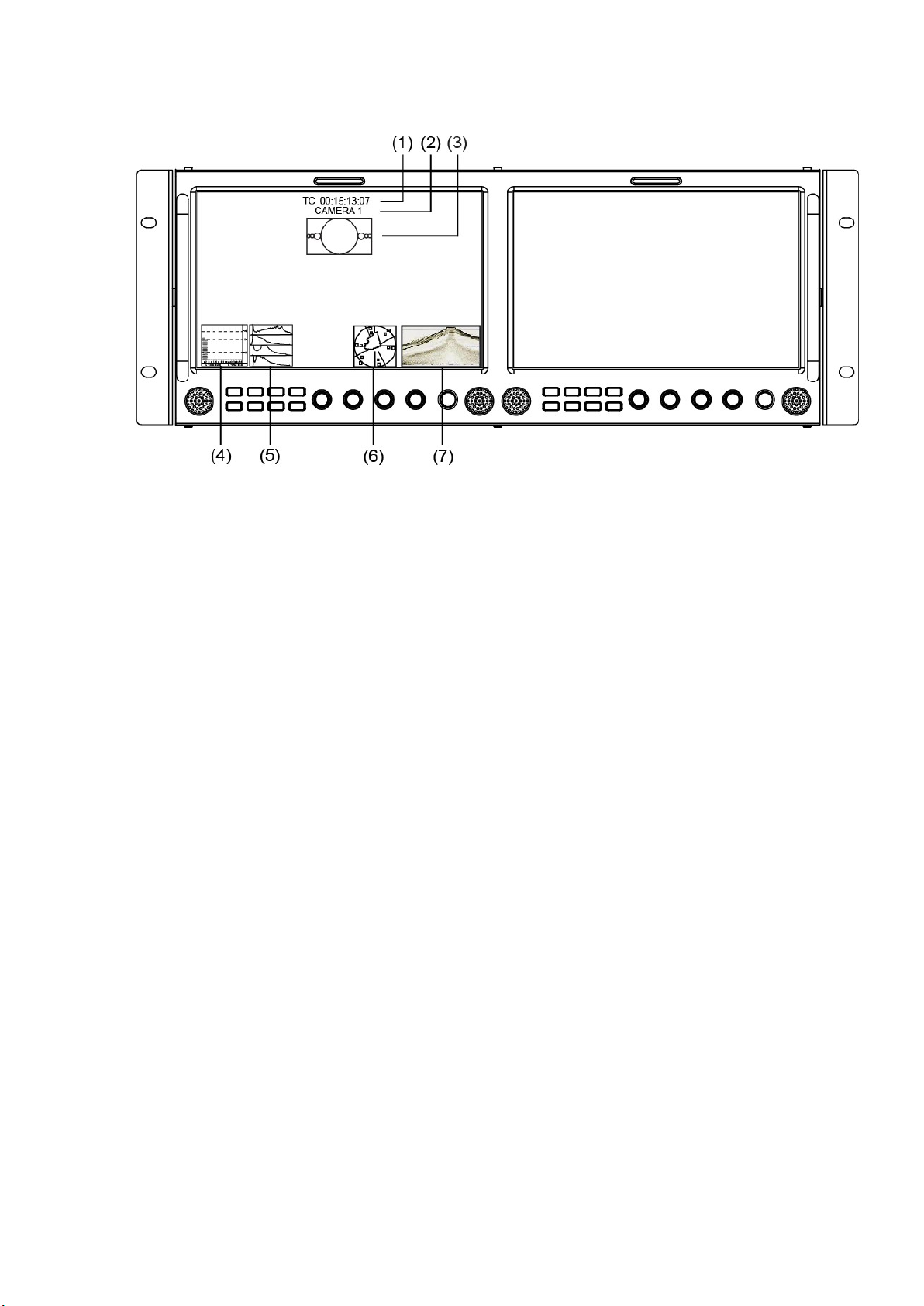
·OSD
⑴ Time code (SDI)
Under SDI input, it can display Time code. If no Time code information is detected, it will be
displayed as “TC: UNLOCKED”.
User can set function keys F1~F5 or GPI pins as “Time code” to turn on or off this function.
⑵ UMD
Set up the UMD under ‘UMD” submenu.
⑶ AFD (SDI)
User can set function keys F1~F5 or GPI pins as “AFD” to turn on or off this function. If no
relevant information is detected, it will be displayed as “AFD: UNLOCKED”.
⑷ Audio
Monitor the audio information. The relevant parameters like position, audio channels and blending,
etc can be changed under “Audio” submenu.
User can set function Keys F1~F5 or GPI pins as “Audio” to turn on or off this function.
⑸ Histogram
User can set function Keys F1~F5 or GPI pins as “Histogram” to turn on or off this function.
⑹ Vector
The relevant parameters like Vector position, Vector color and Vector blending, etc. can be
changed under “Vector” submenu.
User can set function Keys F1~F5 or GPI pins as “Vector” to turn on or off this function.
⑺ Waveform
Press “WFM” on the front panel to turn on/of this function. The relevant parameters like WFM
position, WFM color and WFM blending, etc can be changed under “Waveform” submenu.

8
Introduction of audio and video functions
16-ch embedded audio meters
Under 2K/3G/HD SDI, it displays 16 channels embedded audio meters. Under SD-SDI and HDMI,
it displays 8 channels embedded audio meters. The audio meter is green, and will turn yellow
when audio exceeds -20dB, and turn red when audio exceeds -9dB.
Audio alarm
If the embedded audio value is too low or no embedded audio, it will display “MUTE” or
“UNLOCKED” in the audio bar.
Time code (SDI)
Under SDI input, it can display the SMPTE timecode (VITC1, VITC2 or LTC) on the top of the
screen. If no Timecode information is detected, it will be displayed as “UNLOCKED”.
Waveform (Y, Cb, Cr, R, G, B)
Under SDI and HDMI input, totally 6 kinds of waveforms which are Y, Cb, Cr, R, G and B can be
selected so as to check the brightness and chroma distribution.
Vector
The displayed vector scope pattern is available under both SDI and HDMI, represents saturation
as distance from the center of the circle, and hue as the angle, in standard position, around it.
Histogram (R, G, B, W)
The histogram is a bar graph that shows the distribution of luminance values in the picture.
There’re R, G, B, W histograms that individually displayed simultaneously, available under both
SDI and HDMI.
Internal Color Bar
Under SDI and HDMI input, it has 100% internal color bar which helps to analyze the monitor color
and adjust the display parameter.
Peaking focus assist (red/blue switch)
The Peaking focus assist function is to mark the sharpest edges of the image with red or blue
color under SDI and HDMI input, for users to check if the subjects are focused.
Zebra stripes
Zebra Stripes are used to check if the image is over exposed or not by showing black and white
lines on the monitor. It is considered over exposed when luminance value exceeds 90%.
Freeze Frame
The freeze frame is to capture and display the current broadcast frame.
R/G/B/Mono
R/G/B/Mono is to display only the blue/red/green primary signal or the luminance signal only so as
to monitor the image noise.
False Color
The false color is used to aid in the setting of camera exposure. Under false color mode, there’s a
color chart on the bottom of screen for reference. The color from the dark to the bright will be
displayed as blue, cyan, green, yellow, orange and red in a consecutive way.
AFD (SDI)
It is the abbreviation of active format description. AFD is to display the SDI embedded AFD
information graphically on the screen.
H/V Delay (SDI)
Under SDI input, H/V Delay can be used to display line/field blanking signal, and to observe the
horizontal and vertical synchronous signal.
UMD
When using external control unit, it can display the video source ID and tally information on the
screen.
Image flip
Horizontal, vertical, horizontal and vertical two-way image flip function.
Normal Left to right Up to down 180° Rotate
9
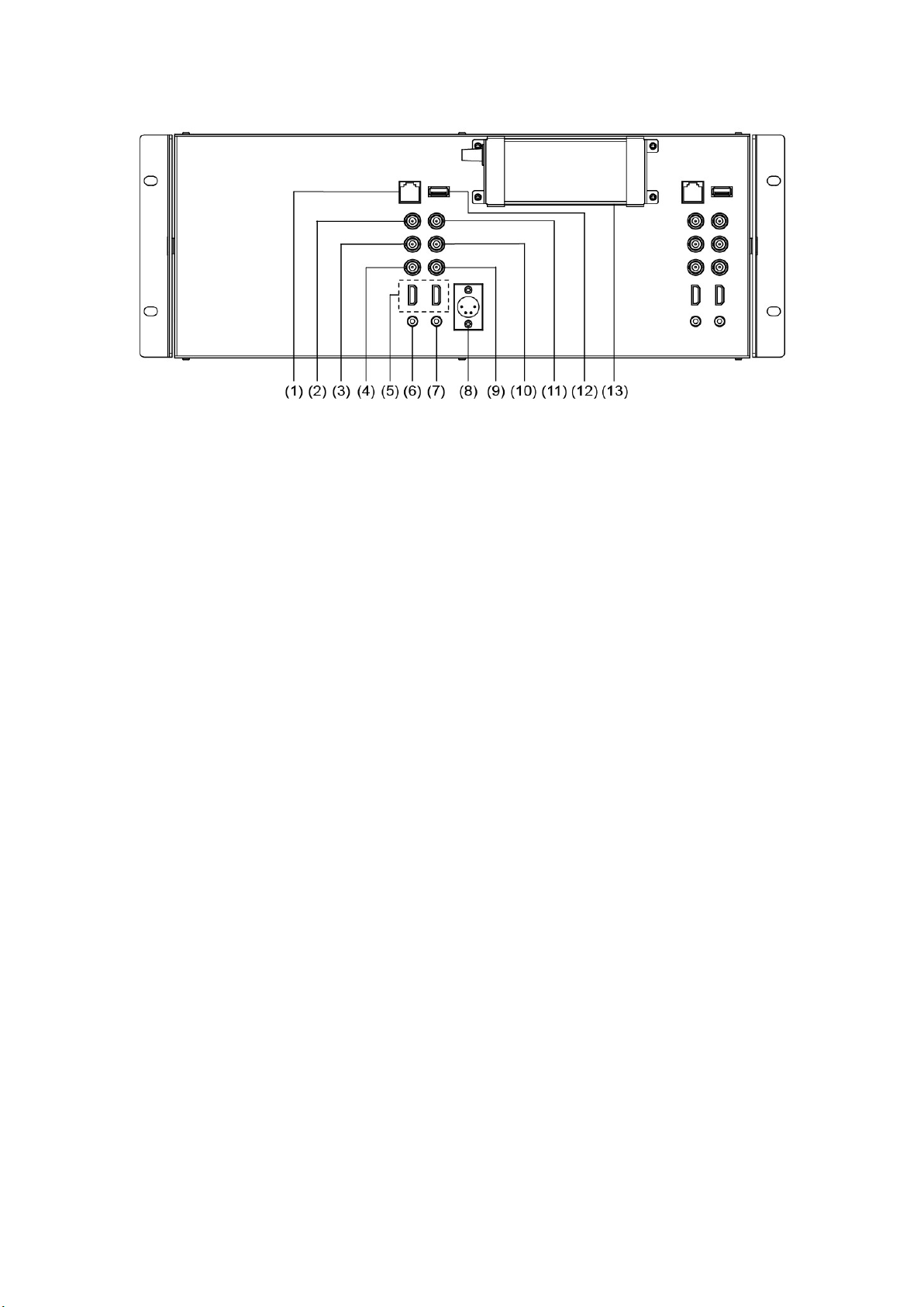
·Rear Panel
⑴ GPI: TSL UMD&GPI control socket
⑵ SDI-LOOP1: SDI loop through output from SDI-IN1 (BNC connector)
⑶ SDI-LOOP2: SDI loop through output from SDI-IN2 (BNC connector)
⑷ CVBS-OUT: CVBS output (BNC connector)
⑸ HDMI Socket
HDMI-IN: HDMI input (HDMI-A connector)
HDMI-OUT: HDMI loop through output from HDMI-IN (HDMI-A connector)
⑹ AUDIO IN: 3.5mm analog audio input (CVBS)
⑺ AUDIO OUT: 3.5mm audio output, to monitor SDI embedded audio, HDMI and analog audio output
⑻ DC 12V IN: Connect with DC12V 4-pin XLR power adapter, support 6.5V-24V voltage input (Pin 1:
Negative, Pin 4: Positive)
⑼ CVBS-IN: CVBS input (BNC connector)
⑽ SDI-IN2: SDI input (BNC connector)
⑾ SDI-IN1: SDI input (BNC connector)
⑿ USB Socket
⒀ Power Adaptor
10
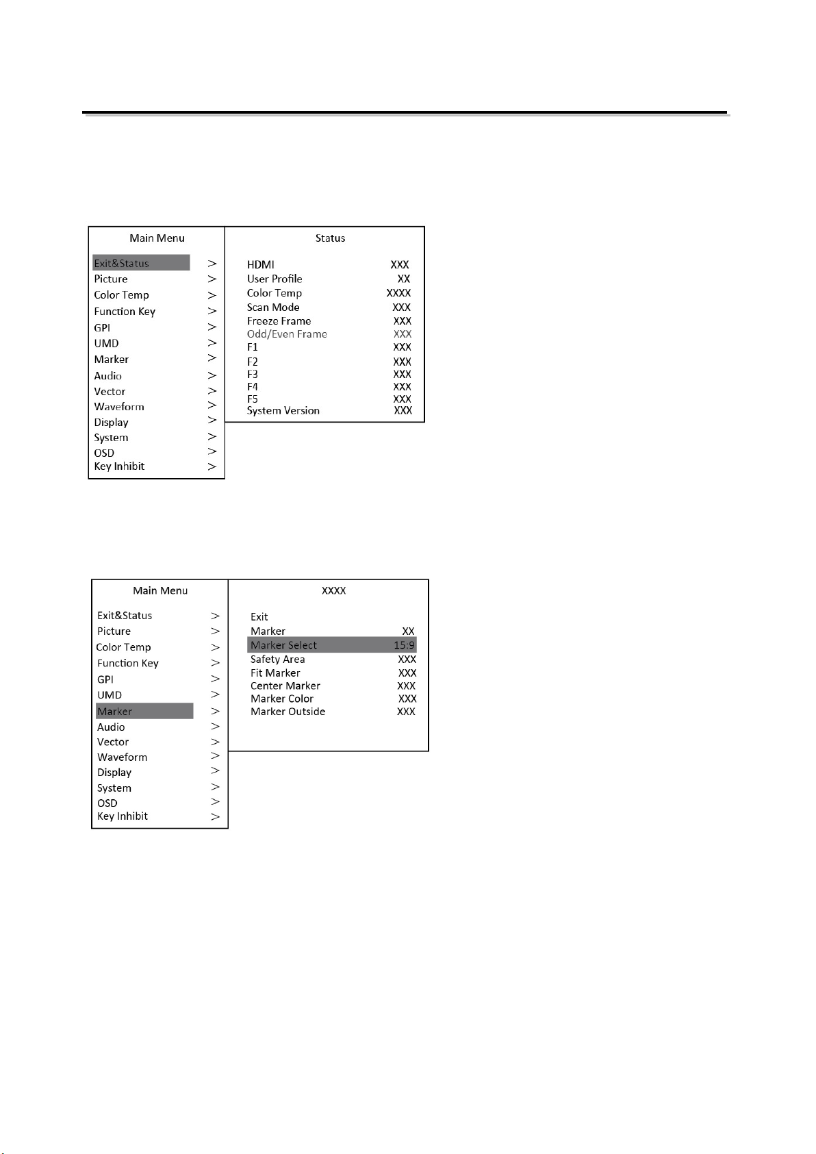
Main Menu
M-1093F has OSD to adjust the parameters and settings, for example: Picture, color temp., function
keys, etc.
1. Press “MENU/ENTER” button, the main menu will popup from the left top of the screen. The
selected main menu highlights in yellow.
2. Revolve “MENU/ENTER” to select submenu, the selected submenu highlights in yellow, press
“MENU/ENTER” to apply and enter into the selected submenu’s items.
3. Revolve “MENU/ENTER” to select the item which needed to adjust, press “MENU/ENTER”, the
selected item and its parameters will be highlighted in yellow.
4. Revolve “MENU/ENTER” to change the selected item’s parameter, press “MENU/ENTER” to apply
and save the settings.
5. Revolve “MENU/ENTER” to select “Exit”, press “MENU/ENTER” to quit submenu. Select “Exit &
Status” under the Main Menu and press to quit Main Menu.
Notice:
* The items in gray cannot be set up.
* If there is no operation under the set time, the menu will automatically save settings and quit.
* If the key inhabit function is turned on, except key inhibit function, all other items are in grey. Please
turn off the key inhibit function to adjust the items.
Table of contents
Other SWIT Monitor manuals


