Important: Water lines MUST be thoroughly ushed BEFORE
and AFTER installing the faucet to prevent foreign matter i.e.
copper chips, sand, stones, etc. from clogging and possibly
damaging the sealing surfaces of the cartridge.
Note: Recommended minimum operating water supply
pressure is 40 psi.
INSTALLATION
(Supply stop valves must have a 3/8” O.D. compression outlet.)
1. S-60 Series: Remove nut and ferrule from supply stops, install
in-line check/screen assembly (LL-71B) on male outlet of stops.
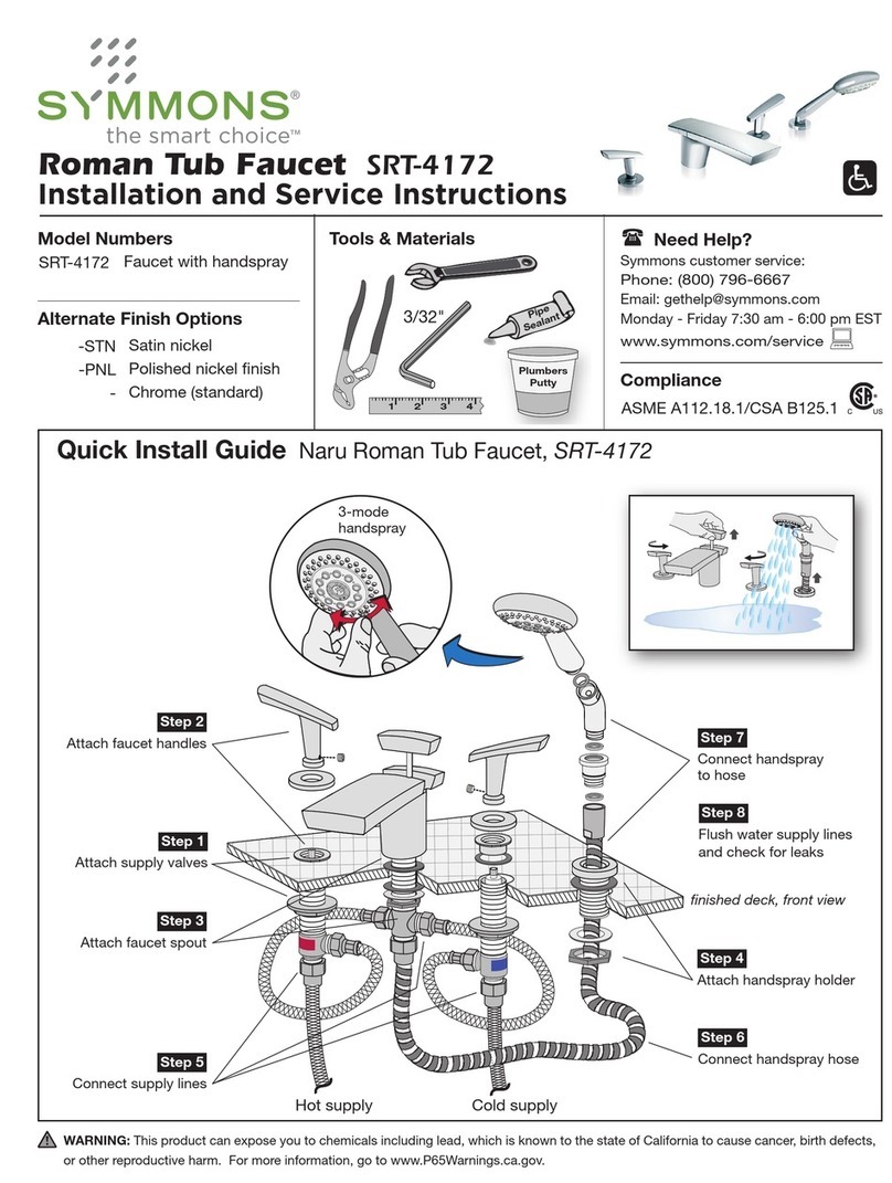
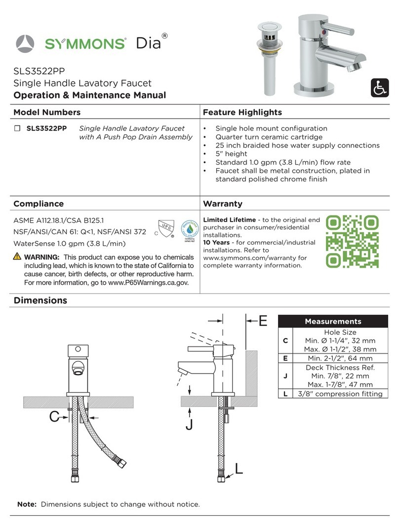
2. Install SPF-KIT loosely on faucet. Position faucet through sink or
counter with mounting gasket under base. Secure faucet tighten-
ing nuts from under side.
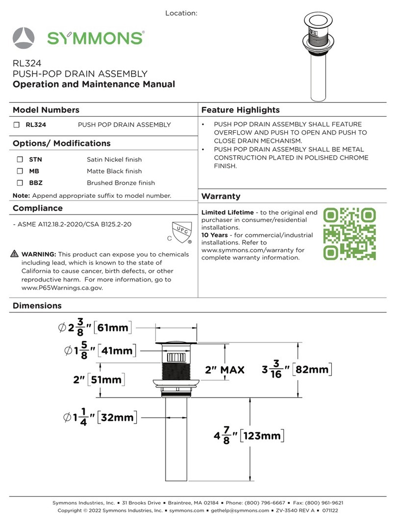
3. Installdrainassembly.Sealunderangewithputty.
4. S-60 Series: Carefully bend copper supplies to meet water
supplies using palms of hands to avoid kinking tubing or fractur-
ing solder joints. DO NOT REMOVE tape on copper supplies.
Connect hot supply to left tube and cold supply to right tube
using appropriate lengths of 3/8” O.D. tubing between faucet
supplies and in-line check/screen assembly.
S-61 Series: Connect cold or tempered supply to faucet supply
using appropriate length of 3/8” O.D. tubing between faucet and
in-line check/screen assembly.
5. S-60 Series:Toushfaucetremoveaerator(LN-100or
LN-101)andturnvalvehandletofullcoldposition.Opensupply
anddepresshandleholdingdownfor10seconds,rotatehandleto
hot position, open supply and repeat above procedure. Hold down
handleandrotatefromlefttorighttoushlinesthoroughly.
Allow faucet to shut off and replace aerator.
S-61 Series:Toushfaucetremoveaerator(LN-100or
LN-101)andopensupplystopdepresshandleandholddownfor
10seconds.Repeatseveraltimesandallowfaucettoshutoff.
Replace aerator.
Adjustment of cycle time and temperature
After faucet has been operated through a number of cycles and
supply water temperature is at designed levels, adjustments to
these features can be made as follows.
Cycle Time: Faucet is factory set to shortest cycle time
with 7 timing washers (LL-28). To increase time, loosen
allen screw (LL-27) with a 3/32” hex socket key, remove
handle(LT-100orRL-156)andremoveoneormoreof
the washers (LL-28) on stem. To reduce time, add washers.
Note: When setting MAXIMUM cycle time, you MUST
maintain at least 5 timing washers (LL-28) so as not to exceed
(perASMEA112.18.1).25gal/cycleat60psi.
Temperature limit adjustment (S-60 Series only):
Loosen allen screw (LL-27) with a 3/32” hex socket key.
Removehandle(RL-156),loosennut(LL-6)andturnstem(LL-
1A)todesiredmaximumtemperature(110°Frecommended).
Turnlimitstopwasher(LL-23N)clockwiseuntilapositivestop
isreachedagainstbackoffaucet.Tightennut(LL-6),replaceand
tightenhandle(RL-156).Faucetwilloperatefromthefullcold
position to the maximum hot temperature that has been set.
Reverse operation (S-60 Series only)
For piping simplicity in back to back installation or when hot
supply is on right, the faucets internal operation can be quickly
reversed.
Removehandle(RL-156),nut(LL-6),andlimitstopwashers
(LL-22N)&(LL-23N),turnstem180°sothatredmarkingis
facing toward front.
Replace limit stop washers, adjust to desired temperature (see
adjustment procedure in preceding paragraph), reassemble faucet
reversing above procedure.
Faucet will operate from the full cold position to the maximum
hot temperature that has been set.
152mm
39
16''
90mm
2"
51mm
23
16''
56mm
32
112mm
41
16''
103mm
coldhot
117
32''
39mm
13
8''
23
8''
35mm
11
4''
32mm
61
2''
165mm
11"
279mm
3
8O.D.
copper
tubes
''
2"
51mm
2"
51mm
60mm
tape
in-line
check/
screen
assembly
9
16 -24 thread
3
8compression
''
61
2''
165mm
152mm
39
16''
90mm
2"
51mm
23
16''
56mm
32
112mm
41
16''
103mm
117
32''
39mm
13
8''
35mm
11
4''
32mm
11"
279mm
3
8O.D.
copper
tube
''
2"
51mm
2"
51mm
23
8''
60mm
in-line
check/
screen
assembly
9
16 -24 thread
3
8compression
''
S-60 Series
S-61 Series
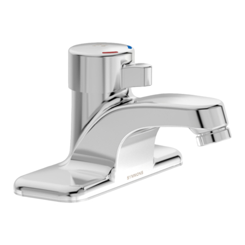
SCOT S-60 Series
Slow-Closing Temperature Lavatory Faucet
Installation & Service Instructions
Metering Faucet S-61 Series
Metering Lavatory Faucet
