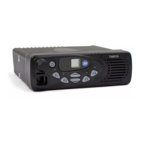
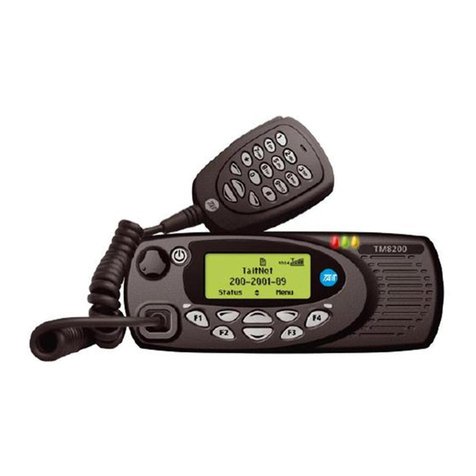
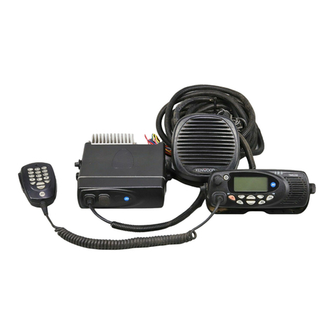
Tait TM9100 User manual

TM9100 mobiles
Installation Guide
MMA-00018-02
Issue 02
August 2005

2 Contact information TM9100 Installation Guide
© Tait Electronics Limited August 2005
Contact information
Tait Radio Communications
Corporate Head Office
Tait Electronics Ltd
P.O. Box 1645
Christchurch
New Zealand
For the address and telephone number of
regional offices, refer to the TaitWorld
website:
Website: http://www.taitworld.com
Technical Support
For assistance with specific technical issues,
contact Technical Support:
E-mail: support@taitworld.com
Website: http://support.taitworld.com
To our European customers:
Tait Electronics Limited is an environmentally responsible company which
supports waste minimization and material recovery. The European Union’s
Waste Electrical and Electronic Equipment Directive requires that this
product be disposed of separately from the general waste stream when its
service life is over. Please be environmentally responsible and dispose
through the original supplier, your local municipal waste “separate
collection” service, or contact Tait Electronics Limited.

TM9100 Installation Guide Contents 3
© Tait Electronics Limited August 2005
Contents
Preface . . . . . . . . . . . . . . . . . . . . . . . . . . . . . . . . . . . . . . . . . . . . . . . . . 5
Scope of Manual. . . . . . . . . . . . . . . . . . . . . . . . . . . . . . . . . . . . . . . . . . . . . . . . .5
Enquiries and Comments . . . . . . . . . . . . . . . . . . . . . . . . . . . . . . . . . . . . . . . . . .5
Updates of Manual and Equipment . . . . . . . . . . . . . . . . . . . . . . . . . . . . . . . . . . .5
Copyright. . . . . . . . . . . . . . . . . . . . . . . . . . . . . . . . . . . . . . . . . . . . . . . . . . . . . .5
Disclaimer . . . . . . . . . . . . . . . . . . . . . . . . . . . . . . . . . . . . . . . . . . . . . . . . . . . . .6
Associated Documentation . . . . . . . . . . . . . . . . . . . . . . . . . . . . . . . . . . . . . . . . .6
Document Conventions . . . . . . . . . . . . . . . . . . . . . . . . . . . . . . . . . . . . . . . . . . .6
Safety Warnings . . . . . . . . . . . . . . . . . . . . . . . . . . . . . . . . . . . . . . . . . . . 8
RF Exposure Hazard . . . . . . . . . . . . . . . . . . . . . . . . . . . . . . . . . . . . . . . . . . . . .8
Safe Radio Mounting . . . . . . . . . . . . . . . . . . . . . . . . . . . . . . . . . . . . . . . . . . . . .8
Interference with Vehicular Electronics . . . . . . . . . . . . . . . . . . . . . . . . . . . . . . . .9
Preparation when Drilling Holes . . . . . . . . . . . . . . . . . . . . . . . . . . . . . . . . . . . . .9
Vehicles Powered by Liquefied Petroleum Gas. . . . . . . . . . . . . . . . . . . . . . . . . . .9
Radio Installation in Gas or Fuel tankers . . . . . . . . . . . . . . . . . . . . . . . . . . . . . . .9
Non-standard Radio Installations. . . . . . . . . . . . . . . . . . . . . . . . . . . . . . . . . . . .10
Negative Earth Supply . . . . . . . . . . . . . . . . . . . . . . . . . . . . . . . . . . . . . . . . . . . 10
1 Preparing the Installation . . . . . . . . . . . . . . . . . . . . . . . . . . . . . . . . . 11
1.1 Regulations . . . . . . . . . . . . . . . . . . . . . . . . . . . . . . . . . . . . . . . . . . . . . . 11
1.2 Installation Tools. . . . . . . . . . . . . . . . . . . . . . . . . . . . . . . . . . . . . . . . . . . 11
1.3 Checking the Equipment for Completeness . . . . . . . . . . . . . . . . . . . . . . . 11
1.4 Choosing an Installation Configuration . . . . . . . . . . . . . . . . . . . . . . . . . . 12
2 Installing the Radio . . . . . . . . . . . . . . . . . . . . . . . . . . . . . . . . . . . . . 14
2.1 Mounting and Removing the Control Head. . . . . . . . . . . . . . . . . . . . . . . 14
2.2 Selecting the Mounting Position . . . . . . . . . . . . . . . . . . . . . . . . . . . . . . .16
2.3 Mounting the U-Bracket. . . . . . . . . . . . . . . . . . . . . . . . . . . . . . . . . . . . . 17
2.4 Installing the Antenna . . . . . . . . . . . . . . . . . . . . . . . . . . . . . . . . . . . . . . . 18
2.5 Connecting the Power Cable to the Power Source. . . . . . . . . . . . . . . . . . 19
2.6 Connecting a Remote Speaker . . . . . . . . . . . . . . . . . . . . . . . . . . . . . . . . 21
2.7 Connecting to the Auxiliary Connector (Ignition Signal, Emergency Switch,
External Alert Devices) . . . . . . . . . . . . . . . . . . . . . . . . . . . . . . . . . . . . . .21
2.8 Installing the Radio. . . . . . . . . . . . . . . . . . . . . . . . . . . . . . . . . . . . . . . . . 25
2.9 Installing the Microphone . . . . . . . . . . . . . . . . . . . . . . . . . . . . . . . . . . . . 26
2.10 Checking the Installation. . . . . . . . . . . . . . . . . . . . . . . . . . . . . . . . . . . . . 27
Tait General Software Licence Agreement . . . . . . . . . . . . . . . . . . . . . . . . 28

TM9100 Installation Guide Preface 5
© Tait Electronics Limited August 2005
Preface
Scope of Manual
ThismanualdescribestheinstallationoftheTM9100mobileradiousingthe
U-bracket, and how to install and connect the microphone, antenna,
emergency switch, and external alert device.
Other cradle mounting arrangements are available for the TM9100 radio,
but are not described in this manual.
The installation of accessories and mounting options is described in the
installation instructions provided with the equipment, and the relevant
section in the service manual.
Enquiries and Comments
If you have any enquiries regarding this manual, or any comments,
suggestions or notifications of errors, please contact Technical Support, Tait
Electronics Ltd, Christchurch, New Zealand (refer to “Contact
information” on page 2).
Updates of Manual and Equipment
In the interests of improving the performance, reliability, or servicing of the
equipment, Tait Electronics Ltd reserves the right to update the equipment
or this manual or both without prior notice.
Copyright
All information contained in this manual is the property of Tait Electronics
Ltd. All rights are reserved. This manual may not, in whole or in part, be
copied, photocopied, reproduced, translated, stored, or reduced to any
electronic medium or machine-readable form, without prior written
permissionfromTaitElectronics Limited.All tradenames referencedarethe
service mark, trademark or registered trademark of the
respective manufacturers.

6Preface TM9100 Installation Guide
© Tait Electronics Limited August 2005
Disclaimer
Therearenowarrantiesextendedor grantedbythismanual.TaitElectronics
Ltd accepts no responsibility for damage arising from use of the information
contained in the manual or of the equipment and software it describes.
It is the responsibility of the user to ensure that use of such information,
equipment and software complies with the laws, rules and regulations of the
applicable jurisdictions.
Associated Documentation
TM9100 User’s Guide.
TM9100 Product Safely and Compliance booklet
TM9100 Service Manual.
Technical notes are published from time to time to describe applications for
Tait products, to provide technical details not included in manuals, and to
offer solutions for any problems that arise.
All available TM9100 product documentation is provided on the CD
supplied with the service kit1. Updates may also be published on the Tait
support website.
Document Conventions
Within this manual, four types of alerts are given to the reader: Warning,
Caution,Important and Note. Thefollowing paragraphs illustrate each type
of alert and its associated symbol.
Warning!! This alert is used when there is a potential risk of death
or serious injury.
Caution This alert is used when there is the risk of minor or moderate
injury to people.
Important This alert is used to warn about the risk of equipment
damage or malfunction.
Note This alert is used to highlightinformation that is required to ensure
procedures are performed correctly.
1. Technical notes are only available in PDF format from the Tait
support website. Consult your nearest Tait Dealer or Customer
Service Organization for more information.

TM9100 Installation Guide Preface 7
© Tait Electronics Limited August 2005
Within this manual, the following symbols are used to highlight differences
between the 40W/50W and the 25W radios:
This symbol highlights information that is relevant to 40W/50W radios.
This symbol highlights information that is relevant to 25W radios.

8 Safety Warnings TM9100 Installation Guide
© Tait Electronics Limited August 2005
Safety Warnings
This section contains important information on the safe installation of the
radio. You must read this information before starting the installation.
You must also read and observe the safety information on radio operation
provided inthe product safety andcompliance information bookletand the
user’s guide.
RF Exposure Hazard
To comply with FCC RF exposure limits:
For 40W/50W radios:
■VHF radios must be installed using an antennamounted centrally onthe
vehicle roof, with a gain of 2.15dBi or 5.15dBi.
■UHF radios must be installed using an antenna mounted either centrally
on the roof with a gain of 2.15dBi or 5.65dBi, or centrally mounted on
the trunk with a gain of 5.65dBi.
For 25W radios:
■The radio must be installed using an externally mounted antenna with a
gain of either 2.15dBi or 5.15dBi.
In all cases, the antenna must not be mounted at a location such that any
person or persons can come closer than 35 inches (0.9m) to the antenna.
Safe Radio Mounting
Warning!! Mount the radio securely so that it will not break loose
in the event of a collision. An unsecured radio is
dangerous to the vehicle occupants.
■Mount the radio and the microphone where they will not interfere with:
■the deployment of passenger airbags
■the vehicle operator controls
■the vehicle operator’s view.
■Do not mount the radio vertically, with the control head facing down.
This will violate compliance with the standards UL/CSA/EN 60950,
Safety of Information Technology Equipment.

TM9100 Installation Guide Safety Warnings 9
© Tait Electronics Limited August 2005
Interference with Vehicular Electronics
Warning!! Some vehicular electronic devices may be prone to
malfunction due to the lack of protection from RF
energy when your radio is transmitting.
Examples of vehicular electronic devices that may be affected by RF
energy are:
■electronic fuel injection systems
■electronic anti-skid braking systems
■electronic cruise control systems
■indicators.
If the vehicle contains such equipment, consult the vehicle manufacturer or
dealer to determine whether these electronic circuits will perform normally
when the radio is transmitting.
Preparation when Drilling Holes
Warning!! When drilling holes in the vehicle, check that drilling
at the selected points will not damage existing wiring,
petrol tanks, fuel lines, brake pipes, or battery cables.
Vehicles Powered by Liquefied Petroleum Gas
Warning!! Radio installation in vehicles powered by LPG
(liquefied petroleum gas) with the LPG container in a
sealed-off space within the interior of the vehicle must
conform to the National Fire Protection Association
Standard NFPA 58. This standard states that the radio
equipment installation must meet the following
requirements:
■The space containing the radio equipment shall be isolated by a
seal from the space containing the LPG container and its fitting.
■Outside filling connections shall be used for the LPG container
and its fittings.
■The LPG container space shall be vented to the outside of
the vehicle.
Radio Installation in Gas or Fuel tankers
Special conditions must be observed when installing a radio on gas and fuel
tankers. Consult your radio provider or Tait-accredited service center for
more details.

10 Safety Warnings TM9100 Installation Guide
© Tait Electronics Limited August 2005
Non-standard Radio Installations
The installation U-bracket described in this guide has been designed so that
there is enough airflow around the radio to provide cooling.
If a non-standard installation method is used, care must be taken that
sufficientheatcanbedissipatedfromthe heatsinkfinsandtheridgedbottom
surface of the radio.
For this to be achieved, there must be a gap of more than 3/8 inch (10mm)
between the bottom surface of the radio chassis and the mounting surface.
This is illustrated in the following diagram:
Negative Earth Supply
The radios are designed to operate only in a negative earth system.
3/8 inch (10 mm)
mounting surface

TM9100 Installation Guide Preparing the Installation 11
© Tait Electronics Limited August 2005
1 Preparing the Installation
This section contains the following information:
■regulations
■installation tools
■checking the equipment forcompleteness
■choosing aninstallationconfiguration.
1.1 Regulations
MPT 1362 Code of
Practice TM9100 mobile radios should be installed in accordance with the MPT
1362 Code of Practice.
Vehicle
Manufacturer’s
Installation
Instructions
Follow your vehicle manufacturer’s instructions for installing mobile radios.
For more information,referto the vehicle manufacturer’s website or contact
the vehicle manufacturer’s dealer.
1.2 Installation Tools
The following tools are required to install of the radio:
■drill and drill bits
■Pozidriv screwdriver
■5/16 inch (8mm) socket
■RF connector crimp tool
■fuse crimp tool
■in-line RF power meter capable of measuring forward and reflected
power at the operating frequency of the radio.
1.3 Checking the Equipment for Completeness
Unpack the radio and check that you have the following:
1. TMAB34 radio body (40W/50W radio), or
TMAB32 radio body (25W radio)
2. TMAC41 control head (including control-head loom)
3. TMAA02-01 microphone, or TMAA02-08 keypad microphone
(including microphone clip and screws)
4. A TMAA03-17 installation kit (40W/50W radio), or
TMAA03-01 installation kit (25W radio), consisting of the
following items:
■U-bracket
■thumbscrews

12 Preparing the Installation TM9100 Installation Guide
© Tait Electronics Limited August 2005
■self-drilling screws and washers
■power cable with DC connector
■fuses
■in-line fuse holders
■receptacles for a remote speaker (remote speaker not included)
■antenna connector.
Refer to the following section, “Installation Kit Options”.
Warning!! Danger of fire. The radio’s protection mechanisms rely
on the correct fuses on both the negative and positive
power supply leads being present. Failure to fit the
correct fuses may result in fire or damage to the radio.
The correct fuse types are:
■40W/50W radios: 20A fuses (Tait IPN 365-00010-81)
■25W radios: 10A fuses (Tait IPN 365-00010-80).
Installation Kit
Options Installation kits are also available without the U-bracket included and with
other antenna connector options. Other cradle mounting arrangements are
also available. Consult your nearest Tait Dealer or Customer Service
Organization for more information.
1.4 Choosing an Installation Configuration
The radio allows for different installation configurations for vehicles with
respect to ignition signal and standby current. For special configurations for
desktop and remote site installations, refer to the service manual.
The installation configurations described below are based on the following
hardware link configuration:
■hardware link 1 (+13.8V battery power sense): fitted
■hardware link 2 (ignition sense): fitted
For more information on the hardware links, refer to the service manual.
Direct Connection to
the Power Source The radio’s power cable must always be connected directly to the power
source (battery).
Important Although it is possible to connect the radio in line with the
vehicle ignition, this is not recommended, as it may draw
too much current and damage the vehicle wiring and
steering column or ignition switch. This may also cause the
supply voltage of the radio to drop below the specified level.
The radio can always be turned on and off using the on/off button,
independent of the ignition signal.
Installation without
Ignition Signal Connect the power cable directly to the power source as described in
“Connecting the Power Cable to the Power Source” on page 19.

TM9100 Installation Guide Preparing the Installation 13
© Tait Electronics Limited August 2005
Note If hardware link 1 is fitted (factory default) and the ignition signal
is not used, the standby current is approximately 50mA. To reduce
the standby current to <3mA either:
■remove hardware link 1, or
■connect pin 4 (AUX GPI3) to pin 15 (AGND) of the
auxiliary con0nector.
Note
With the above two options, the radio always stays off when power is
first applied. The radio can only be turned on with the on/off button.
Installation with
Ignition Signal Connect the power cable directly to the power source as described in
“Connecting the Power Cable to the Power Source” on page 19.
Connect pin4 (AUX GPI3) ofthe auxiliary connector tothe ignitionsignal
as described in “Connecting to the Auxiliary Connector (Ignition Signal,
Emergency Switch, External Alert Devices)” on page 21.
The AUX GPI3 line must be programmed to ‘Power Sense (Ignition)’ and
active to ‘High’. For more information, refer to the online help of the
programming application.
Note The TMAA04-05 ignition sense kit provides a suitable mating plug
fortheradio’s auxiliaryconnector.Theplugincludeswiringforthe
the ignition signal and analog ground.

14 Installing the Radio TM9100 Installation Guide
© Tait Electronics Limited August 2005
2 Installing the Radio
This section contains the following information:
■mounting and removing the control head
■selecting the mounting position
■mountingtheU-bracket
■installing the antenna
■connecting the power cable to the powersource
■connecting a remote speaker
■connecting to the auxiliaryconnector(ignitionsignal,
emergency switch,externalalertdevices)
■installing the radio
■installing the microphone
■checking the installation.
2.1 Mounting and Removing the Control Head
Important The control head contains devices which can be damaged
by static discharges. Always install or remove the control
head in a static-safe environment. For information on
antistatic precautions, go to the Electrostatic Discharge
Association (ESD) website, http://www.esda.org.
Mounting the
Control Head The control head and its connection loom are delivered separately from the
radio body. Before installing the radio, the control head should be mounted
on the radio body.
The orientation of the radio body determines which way up the control
head is mounted on the radio body.
Note It may be required to mount the radio upside down to maintain a
gap of more than 3/8 inch (10mm) for air circulation between the
underside of the radio body and the mounting surface.

TM9100 Installation Guide Installing the Radio 15
© Tait Electronics Limited August 2005
1. Plug the control-head loom onto the control-head connector.
2. Insert the bottom edge of the control head onto the two clips in the
front of the radio body, then snap into place.
Removing the
Control Head Important During this procedure, take care that the control-head seal
is not damaged. Damage to this seal reduces
environmental protection.
On the underside of the radio, two lever points are indicated on the radio
body by a dot-dash-dot pattern ( ). The lever point is between the
control-head seal and the control head.
1. At either of the lever points, insert a 3/16 inch (5mm) flat-bladed
screwdriver between the control head and the control-head seal.
2. Use the screwdriver to lift the control head off the chassis clip, then
repeat in the other position. The control head can now be removed
from the radio body.
Figure 2.1 Mounting the control head
Figure 2.2 Removing the control head
lever point
indication of
lever point
control-head
seal
control head

16 Installing the Radio TM9100 Installation Guide
© Tait Electronics Limited August 2005
2.2 Selecting the Mounting Position
Requirements for
Safe and Convenient
Installation
Ensure the mounting position complies with the following safety warnings:
Warning!! Safe radio mounting
■Mount the radio securely so that it will not break loose in the event of a
collision. An unsecured radio is dangerous to the vehicle occupants.
■Mount the radio and the microphone where they will not interfere with:
■the deployment of passenger airbags
■the vehicle operator controls
■the vehicle operator’s view.
Gap Between
Radio Body
and Mounting
Surface
Note It may be necessary to mount the radio upside down to maintain a
gap of more than 3/8 inch (10mm) between the bottom surface of
the radio body and the mounting surface.
Inspect the vehicle and determine the safest and most convenient position
for mounting the radio. Make sure that there is sufficient clearance behind
the radio for the heatsink and cables.
IP54 Protection
Class Considerations The radio fulfils the requirements of the IP54 protection class.
Important However, do not mount the radio in areas where it can be
temporarily submerged from an accumulation of water or
other liquids (e.g. when using a high-pressure
cleaning device).
The IP54 protection class does not apply when:
■the control head is removed from the radio body
■the bungs are removed from the auxiliary connector or the cavity for the
external options connector (fitting an auxiliary connector or external
options connector will not restore the IP54 protection class)
■the microphone grommet is not installed.

TM9100 Installation Guide Installing the Radio 17
© Tait Electronics Limited August 2005
2.3 Mounting the U-Bracket
The U-bracket can be used to install the radio on the dashboard or on any
sufficiently flat surface (e.g. cabin floor or trunk). The U-bracket can be
mounted using the self-drilling screws and washers provided in the
installation kit, or nuts and bolts (not included).
Caution Although an industrial-strength recloseable fastening system
can be used to support the installation, for safety reasons Tait
does not recommend this as a mounting option.
Important When mounting the radio on a surface, check whether the
mounting screws will screw into material providing
sufficient strength. Reinforce the mounting surface,
if required.
1. If the U-bracket is being mounted over a curved surface, bend the
tabs at the bottom of the U-bracket slightly to match the
surface shape.
2. Hold the U-bracket in the position chosen for the radio and use the
mounting holes as a template to mark the mounting locations.
Use at least four screws to install the U-bracket.
Tip The screws provided are self-drilling. For more precise positioning,
predrill ∅1/8 inch (3mm) pilot holes for self-drilling screws.
Reduce the hole size in metal that is less than 1/32 inch
(1mm) thick.
Important Ensure that drilling at the selected points will not damage
existing wiring.
3. Drill any holes required for cables and install suitable grommets or
bushings in the holes.
4. Screw the U-bracket in the chosen mounting position using the self-
drilling screws and washers provided. When tightening the screws,
ensure that this does not distort the U-bracket.
Figure 2.3 Mounting the U-bracket

18 Installing the Radio TM9100 Installation Guide
© Tait Electronics Limited August 2005
2.4 Installing the Antenna
This section provides information on installing an external antenna within
the RF exposure limits.
Install the external antenna according to the antenna manufacturer’s
instructions. Good quality 50Ωcoaxial cable must be used, such as RG58
or UR76.
Important Route the cable in a manner that minimizes:
■coupling into the electronic control systems of
the vehicle
■coupling of electric vehicle systems, such as alternators,
into the radio.
Avoid sharp bends in the cable. These distort the cable and
alter its electrical characteristics.
Warning!! RF exposure hazard
To comply with FCC RF exposure limits:
1. Mount the antenna at a location such that no person or persons can
come closer than 35 inches (0.9m) to the antenna.
2. For 40W/50W radios:
■VHF radios must be installed using an antenna mounted centrally
on the vehicle roof, with a gain of 2.15dBi or 5.15dBi.
■UHF radios must be installed using an antenna mounted either
centrally on the roof with a gain of 2.15dBi or 5.65dBi, or
centrally mounted on the trunk with a gain of 5.65dBi.
3. For 25W radios, the radio must be installed using an externally
mounted antenna with a gain of either 2.15dBi or 5.15dBi.
Terminating the
Antenna Cable 1. Run the free end of the coaxial cable to the radio’s mounting position
and cut it to length, allowing approximately 8 inches (20cm) excess
at the radio end.
2. Terminate the free end of the antenna cable with the mini-UHF plug
or BNC plug (supplied) as shown in Figure 2.4.
Figure 2.4 Terminating the antenna cable
5/16"
9/16"
5/32"
(4 mm)
(8 mm)
(14 mm)

TM9100 Installation Guide Installing the Radio 19
© Tait Electronics Limited August 2005
2.5 Connecting the Power Cable to the Power Source
This section provides information on connecting the power cable to the
power source.
Power Connector The power connector is the interface to the vehicle battery and an optional
external remote speaker. Connecting a remote speaker is described in
“Connecting a Remote Speaker” on page 21.
Important This radio is designed to operate from a nominal 12V
negativegroundsupplyandmaydrawupto15Aofcurrent.
The radio will tolerate a supply voltage range of 10.8V to
16.0V at the radio.
Selecting the Power
Source In passenger vehicles, the radio is always connected directly to the battery
using the power cable provided.
In trucks, where direct connection to the battery is often not possible, the
radio can be connected to a suitable terminal inside the fuse box that is
connected directly to the battery.
24V-to-12V
Converter In vehicles with a supply voltage larger than 16.0V, such as many trucks, it
is essential to provide a suitably rated 24V-to-12V converter. This will
isolate the radio from excessive battery voltage and provide the correct DC
operating conditions. Note that most 24V-to-12V converters already fitted
are not rated sufficiently.
Standby Current When connecting the radio to the battery without using the ignition signal
as described on page 23, the standby current is approximately 50mA.
When using the ignition signal to turn off the radio, the standby current is
reduced to <3mA.
Tip Toreducethestandbycurrentfrom 50mAto<3mAwithoutusing
the ignition signal, connect pin 4 (AUX GPI3) and pin 15 (GND)
of the auxiliary connector.
Table 2.1 Power connector (radio)—pins and signals
Pinout Pin Signal name Description Signal type
1 AGND Earth return for radio body power source Ground
2 SPK– External speaker output. Balanced load
configuration Analog
3 SPK+ External speaker output. Balanced load
configuration Analog
4 13V8 BATT DC power input for radio body and
control head Power
rear view
40W/50W radio
1 2 3 4
rear view
25W radio

20 Installing the Radio TM9100 Installation Guide
© Tait Electronics Limited August 2005
Connecting the
Power Cable Important Although it is possible to connect the radio in line with the
vehicle ignition, this is not recommended, as it may draw
too much current and damage the vehicle wiring and
steering column or ignition switch. This may also cause the
supply voltage of the radio to drop below the specified level.
Important Disconnecting the vehicle’s battery may cause problems
with some electronic equipment, such as vehicle alarms,
engine management systems, and in-car entertainment
systems. Check that the vehicle owner has the necessary
information to make all electronic equipment function
correctly after battery reconnection.
Important If the battery is not disconnected, exercise extreme caution
during the installation and install the fuses only when the
installation is ready to be checked. For more information,
refer to “Checking the Installation” on page 27.
1. Disconnect the vehicle’s battery unless specifically prohibited from
doing so by the customer, vehicle manufacturer, agent, or supplier.
Important Route the cable in a manner that minimizes coupling of
electric vehicle systems such as alternators into the radio.
Important Protect the power cable from engine heat, sharp edges and
from being pinched or crushed.
2. Run the power cable between the radio’s mounting position and the
power source and cut it to length, allowing approximately 8 inches
(20cm) excess at the radio end.
3. Plug the power cable into the power connector of the radio.
4. Cutthe negativeand the positive wires where the in-line fuse holders
will be placed (as close to the power source as possible).
Important Do not install the fuses until the installation is ready to be
checked. For more information, refer to “Checking the
Installation” on page 27.
5. Insert each end of the negative wire into each of the fuse
crimp-terminals and crimp them to force the metal contacts onto
the wires.
6. Push the two crimp-terminals into the clear plastic fuse cover. Close
the cover while the next steps are completed.
7. Repeat steps 5 and 6 for the positive wire.
8. Connect the negative wire to the battery ground terminal
9. Connect the positive wire to the battery positive terminal.

TM9100 Installation Guide Installing the Radio 21
© Tait Electronics Limited August 2005
Important Do not install the fuses until the installation is ready to be
checked. For more information, refer to “Checking the
Installation” on page 27.
2.6 Connecting a Remote Speaker
If a high-power remote speaker is required, Tait recommends using:
■TMAA10-06 high-power remote speaker for 40W/50W radios
■TMAA10-03 high-power remote speaker for 25W radios.
If a different speaker is used, receptacles for the speaker pins of the power
connector are provided with the installation kit.
Connect the speaker to pins 2 (SPK–) and 3 (SPK+) of the power
connector described on page 19.
For more information, refer to the installation instructions provided with
the speaker, or to the relevant section of the service manual.
2.7 Connecting to the Auxiliary Connector (Ignition Signal,
Emergency Switch, External Alert Devices)
The auxiliary connector can be used toconnect external devices andsignals
that are typically connected to a radio. These devices and signals include:
■the ignition signal to power up and power down the radio
■an emergency switch to power up the radio (if required) and then enter
emergency mode
■external alert devices.
Auxiliary Connector The radio’s auxiliary connector is a 15-way standard-density
D-range socket.
Note The space for a mating plug is limited to 1 5/8 inch (41mm) in
width and 11/inch (18mm) in height. It is recommended that you
test the plugto beused before manufacturing a cable. Tait usesIPN
240-00020-55 for the plug.
Other manuals for TM9100
8
Table of contents
Other Tait Radio manuals

Tait
Tait TM8260 User manual

Tait
Tait TM9100 Installation instructions

Tait
Tait TM8260 Installation guide

Tait
Tait TM8200 mobiles User manual

Tait
Tait TM8260 User manual

Tait
Tait T8000 Quick start guide

Tait
Tait TM9300 User manual

Tait
Tait TM8200 mobiles User manual

Tait
Tait TM8000 Series Instructions for use

Tait
Tait TM9100 Series P25 User manual

Tait
Tait t2020 User manual

Tait
Tait T2000 Series User manual

Tait
Tait TM8105 User manual

Tait
Tait TM8000 Series User manual

Tait
Tait TM8000 Series User manual

Tait
Tait TM9400 User manual

Tait
Tait T2000-300 Quick start guide

Tait
Tait T2020 Series II User manual

Tait
Tait TM9300 User manual

Tait
Tait TM8100 mobiles User manual