OPERATION5
SETTING6
2/4
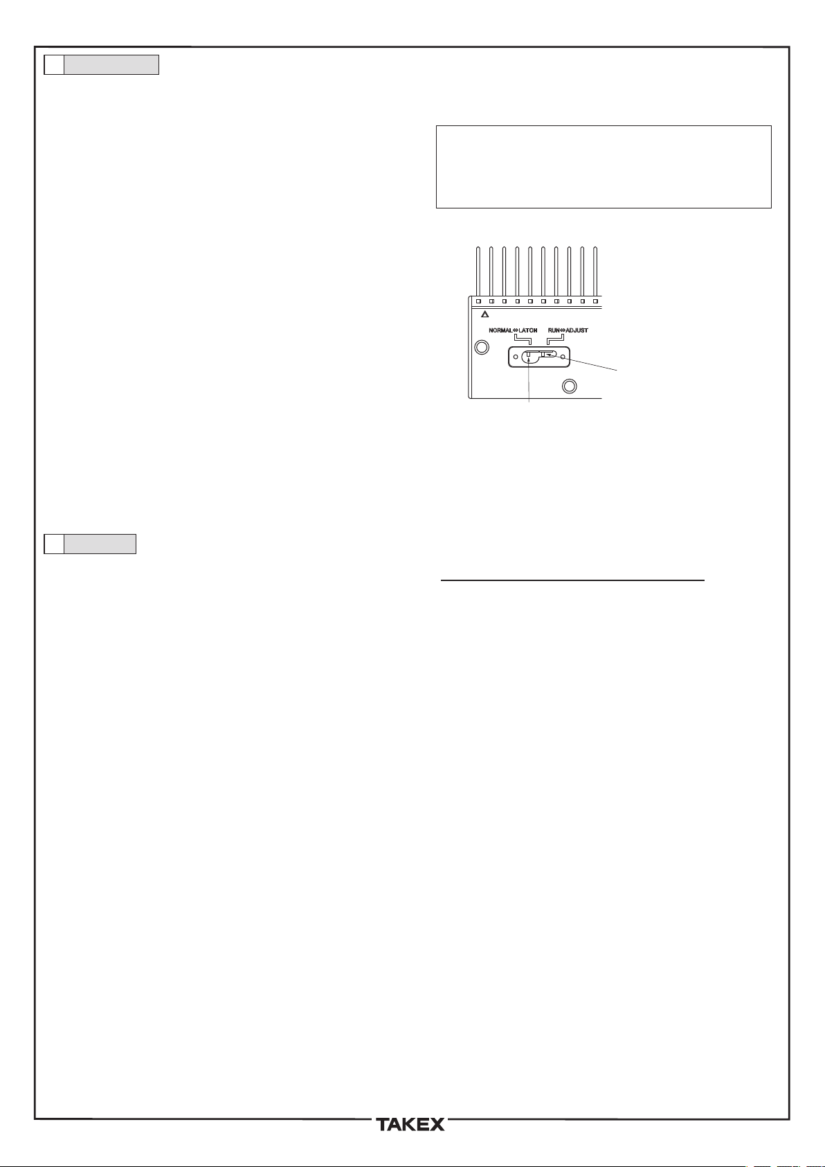
・Left-sidesetting:Standardoperationmode(defaultsetting)
・Right-sidesetting:Automaticsensitivityadjustmentmode
●
Preparation
Firmlysecurethewiringconnectorsasdescribedinsection4
"Connections".BeforeturningthepowerON,removetheswitch
coverandmaketheappropriateswitchselections(seesection6(1)
"Switches").
*Afterchangingtheswitchsettings,besuretoturnthepower
OFFandbackON.
(1)TurnthepowerON.
*BeforeturningthepowerON,checkagaintoverifythatthe
connectionsarecorrect.
Usecarebecausetheoutputsarenotequippedwithshort-circuit
protectioncircuits.
(2)TheTEACHmodeisestablishedwhenthepoweristurnedON.
*WhenintheTEACHmode,verifythatnothingisblockingthelight
beam.
(3)Performstandardoperation(seesection6(2)"Functions").
*Becausetheproducthasbeenadjustedtodetectwaferswhich
arenearlytransparent,anfalseoutputcouldoccuriftheproduct
issubjectedtoanimpactshockorvibrationwhilethesensoris
movingorstationary.
Moreover,amalfunctioncouldoccurifthecomb'stipistouched
bythewafer,orbyafinger.
Ifthecombistouchedinthismanner,theTEACHoperationmust
berepeated(seesection6(2)"Functions").
*Ifthecombbecomesdamaged,replaceitasdescribedinsection
8"MaintenanceandInspection".
(1)Switches(seeFig.1)
Openthesensor'sswitchcover,thenspecifythedesiredoperation
modebysettingthetwoswitches.
●
SwitchA(outputoperationsetting)specifiesthesensor
outputoperation.
・Normaloutputmode:settheswitchtotheleft.
(OutputON/OFFoccursaccordingtoobjectpresence/absence.
Thisisthedefaultsetting.)
・Latchoutputmode:settheswitchtotheright
(OncetheoutputswitchesON,thisONstatusismaintained.)
*Thelatchoutputmode(sensoroutputONHOLD)canbe
canceledbyexecutingtheLightemissioninhibitsignal.
●
SwitchB(automaticsensitivityadjustmentsetting)is
usedforsensorsensitivityadjustments.
Thisadjustmentoperationautomaticallyadjuststhesensitivityof
eachopticalaxischannelindividuallyandisrequiredonlyaftera
combhasbeenreplaced.
Besuretoperformtheadjustmentafterreplacingacombwhichhas
becomedamaged,etc.
SettheswitchBtoautomaticsensitivityadjustmentmodeandturn
thepowerON.
Besurethatnothingisblockingthelightduringtheautomatic
sensitivityadjustmentoperation(lightreceptionisrequiredatthis
time).
Followingtheautomaticsensitivityadjustmentoperation,besureto
returntheswitchsettingtothestandardoperationsuretoreturn
theswitchsettingtothestandardoperation
SwitchA:Outputoperationsetting
Normaloutputmode←→Latchoutputmode
SwitchB:Automaticsensitivityadjustmentsetting
Standardoperationmode←→Automaticsensitivityadjustment
(2)Functions
●
PowerONandTEACHoperation
WhenpoweristurnedONinthestandardoperationmode,the
internalcircuit'soperationischecked,andaninitialTEACH
operationoccurs.
BesurethatnothingisblockingthelightatpowerON.
Ifteachingcannotbeperformedforsomereason(lightisblocked,
combismissingordamaged,etc.),theerroroutputturnsON,and
theerrorchannel'soutputturnsON/OFFrepeatedly.
●
Outputinhibitinput
Turnseachchannel'sopencollectoroutputOFFregardlessofthe
sensoroperationstatus.
Thisfunctioncanbeusedwhentheoutputsofmultiplesensors
areconnectedinparalleltoaPLC.
Thisfunctioninhibitstheoutputsofunnecessarysensorswhichis
areconnectedtothePLC.
●
Lightemissioninhibitinput
WhenthisinputisturnedON,a"lightblocked"and"outputON"
statusoccursatallchannels.
WhenthisinputisturnedOFF,are-teachingoperationoccurs.
Performthisre-teachingoperationwhilethesensorremains
stationary.
Donotperformare-teachingoperationwhilethesensorisinmotion.
There-teachingoperationiscompletedwithinapproximately1sec
afterthelightemissioninhibitinputisturnedOFF.
After1secelapses,performamotionoperation.
Toobtainoptimaldetection,turnthelightemissioninhibitinputON
→OFFwhilethesensorisinastandbystatus(beforeproceeding
tothewaferdetectionoperation)inordertoperformre-teaching.
●
Erroroutput
AnerroroutputisissuedatpowerONifanoperationalproblem
exists(abnormalchannelcondition,insufficientlightreception,
lightabnormalityduetoadamagedcomb,malfunctiondueto
ambientlightinterference,etc.).
WhentheerroroutputturnsON,theerrorchannel'soutputturns
ON/OFFrepeatedly.
SwitchA:Outputoperation,setting(factorysetting)
SwitchB:Automatic
sensitivityadjustmentsetting

 User manual")


