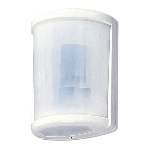
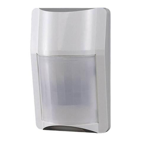
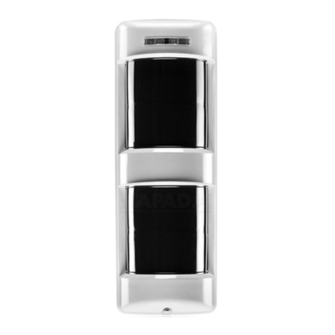
Takex PIR-T40NAM User manual

①
PIR-T40NAM (W) is passive infrared sensor that detects far-infrared rays emitted from the human body and outputs a contact signal.
Since this unit significantly reduces lost and false detection using the unique triple mirror and signal processing systems, it can be
used both for indoor and outdoor applications. This unit has the following features suitable for multiple applications.
• Detection distance up to 115’(40m)(Max 150'(45m) with high density mode)
• Detection distance and direction adjustable
• Mounting height of 6.6’ to 13’(2 to 4m) for normal operation (max. 20’(6m) in specialized operation modes)
• Equipped with N.C. contact output for security and N.O. contact output for activation of ancillary devices
• Can be mounted on wall surfaces, as well as on poles, ceilings, and under eaves using the optional accessories (sold separately)
• Equipped with anti-masking and back tamper functions for more secure protection
[Cover unit]
Memory LED
: Red (embedded)
Alarm LED
: Red (embedded) Cover locking screw
Wiring hole for
exposed wiring
(Knockout)
Wiring hole
(with grommet)
Back tamper
[Sensor unit]
Mode setting
table Area setting
table
Mode selector
Indicator
Area selector
Alignment
lever
[Mirror unit]
Terminal block
Wiring hole
(with grommet)
Mirror
locking screw
Accessories
Tapping screw
φ4×30
(4 pcs)
Instruction
manual
This document
Area masking sheet
(1 sheet)
Anti bird spike
(3 pcs)
Thank you for purchasing this product.
Before using the product, please read this instruction manual to ensure correct operation.
TRIPLE MIRROR PASSIVE SENSOR
Instruction Manual
PIR-T40NAM (W)
1PRODUCT DESCRIPTION
2PARTS DESCRIPTION
Wiring hole for
exposed wiring
(Knockout)
(Vertical curtain protection)

②
Pets, such as dogs, cats, and birds
Shielding objects Places that people can easily touch
Strong light that hits the sensor
Strong vibration and/or electric noise
Warning
Caution
Do not use the unit with power voltage levels other than
those specied. Failure to follow this may result in re,
electric shock, and/or malfunction.
Do not connect devices that exceed the indicated capacity to
the output contact of the unit. Failure to follow this may
result in electric shock, re, and/or malfunction.
Do not touch terminals with wet hands. Failure to follow
this may result in electric shock.
If the following errors/malfunctions occur, power off the
unit immediately, and contact your dealer.
Failure to follow this may result in re, electric shock,
and/or malfunction.
t4NPLFBCOPSNBMPEPSBOEPSTPVOEBSFGPVOE
t-JRVJETVDIBTXBUFSBOEPSGPSFJHONBUFSJBMIBT
entered the unit
t5IFVOJUJTEFGPSNFEBOEPSQBSUTBSFEBNBHFE
%POPUEJTBTTFNCMFPSNPEJGZUIFVOJU
Failure to follow this may result in re, electric shock,
and/or malfunction.
Mount the unit on a solid ceiling or wall surfaces where
reinforcement materials are used. If you mount the unit on
OPOXPPEQMBTUFSCPBSEPSDPODSFUFTFDVSFMZNPVOUJUVTJOH
anchors and mounting screws that match the wall
materials. Failure to follow this may result in injury and/or
property damage if the unit falls.
Do not install the unit in a place and/or with a mounting
method that cannot support its weight.
Failure to follow this may result in injury and/or property
damage when the unit falls.
Do not apply impact to the unit.
Applying strong impact to the unit may result in
performance deterioration and/or damage to the unit.
5IFVOJUNBZOPUPQFSBUFQSPQFSMZOFBSEFWJDFTUIBU
generate a strong electric or magnetic eld. Also, devices
near the unit may not operate properly due to the
magnetic eld and/or magnetism generated from the unit.
.BLFTVSFUPDIFDLJUCFGPSFPQFSBUJPO
Make sure to perform sufcient operation checks on the
XIPMFTZTUFNCFGPSFPQFSBUJPO
4FDVSFMZDPOEVDUJOTUBMMBUJPOXPSLBDDPSEJOHUPUIF
instruction manual. Also, make sure to use the supplied
accessories and specied components. Failure to follow this
may result in injury and/or property damage in the event
of re or electric shock, if the unit falls.
$POUBDURVBMJĀFEQFSTPOOFMGPSBOZFMFDUSJDBMXPSL
OFDFTTBSZGPSJOTUBMMBUJPOJGSFRVJSFE
Failure to follow this may result in re and/or electric
shock.
%POPUJOTUBMMUIFVOJUJOQMBDFTTVCKFDUUPPJMTNPLFTUFBN
high humidity, and/or a lot of dust. Electricity transmitted
through oil, water, and/or dust may result in re, electric
shock, and/or false operation.
%POPUQFSGPSNBFSJBMXJSJOHPGQPXFSBOETJHOBMDBCMFT
Failure to follow this may result in electric shock, re,
and/or malfunction.
Passive infrared sensors are designed to detect changes of
far-infrared ray energy. Energy changes largely when the
IVNBOCPEZNPWFTBDSPTTUIFEFUFDUJPOBSFB)PXFWFS
FOFSHZEPFTOPUDIBOHFHSFBUMZXIFOUIFIVNBOCPEZ
comes closer in a straight line, or stops.
In addition, if the
detection area
environment generates
similar changes due to
certain factors, the unit
will issue an alarm
XJUIPVUCFJOHBCMFUP
judge properly.
Avoid installing the unit in the following places. Otherwise,
false detection may occur.
t1MBDFTTVCKFDUUPTUSPOHEJSFDUPSSFāFDUFEMJHIUTVOMJHIU
spotlight)
t1MBDFTTVCKFDUUPSBQJEUFNQFSBUVSFāVDUVBUJPOTBJS
PVUMFUTPGBJSDPOEJUJPOJOHFRVJQNFOUFUD
t1MBDFTXIFSFNPWJOHPCKFDUTBSFJODMVEFEJOUIFEFUFDUJPO
BSFBUSFFTCSBODIFTBOEMFBWFTMBVOESZFUD
t1MBDFTTVCKFDUUPTUSPOHWJCSBUJPOBOEPSFMFDUSJDOPJTF
t1MBDFTXIFSFEPHTDBUTCJSETBOEPSBVUPNBUJDDMFBOJOH
SPCPUTNBZQBTT
t1MBDFTXIFSFTIJFMEJOHPCKFDUTJODMVEJOHHMBTTBOE
transparent resin, etc.) are included in the detection area
TIBEJOHQBSUTXJMMOPUCFEFUFDUFE
t1MBDFTXIFSFUIFTFOTPSQBSUMPPLTJODMJOFEGSPNUIFGSPOU
WJFXUIFBSFBDBOOPUCFQSPQFSMZDPOĀHVSFE
t1MBDFTUIBUJOUSVEFSTDBOFBTJMZUPVDI
4FUUIFBSFBXJUIJOUIFSBUFEEFUFDUJPOEJTUBODFSBOHF
according to the instruction manual. If you use the unit
outside the specied range, an appropriate area will not
IBWFCFFODPOĀHVSFEBOEUIFVOJUNBZPQFSBUFVOTUFBEJMZ
and/or detection may fail.
Air outlets of air-conditioning
equipment
Sunlight reflection
Trees, branches and leaves, laundry
Warning Caution
A prohibited action you must not do.
An action you must do, and information you
should keep in mind
3PRECAUTIONS This manual describes precautions by classifying them based on degrees of danger and
damage that would be generated if using the unit incorrectly.
Be sure to observe
This indicates the possibility of severe
injury, and even death, if ignored or a
user handles the unit incorrectly.
This indicates the possibility of minor injury and/or
damage to properties, or of a notification delay in
your system due to false operations and/or
non-detection, if ignored or a user handles the unit
incorrectly.
We categorize these precautions throughout the manual using the following symbols.
③
Caution
Refer to the detection area chart, and select the installation
location. Then, check the actual operation, and adjust the
appropriate area.
Perform the operation check after installation and also on
periodic basis to make sure that there is no problem in the
operation.
Install the unit in the
location where the
detection area faces toward
a place that intruders may
pass through.
After installation, make
sure to adjust the detection
area and perform sufcient
operation check.
This unit is for wall mounting. When installing it on poles,
ceilings, or under eaves, use the specied attachments (sold
separately).
This unit has a rainproof structure, not a waterproof
structure. Do not hose it directly. Do not use the unit in
places subject to water and/or constant high humidity, such
as bathroom. Failure to follow this could result in
malfunction.
Avoid operation in places where there is not enough space
for the detection area to pass through without being
obstructed. It may cause false or lost detection.
When this operation is obliged, selecting "high density
mode" is recommended.
Note, however, that the performance to prevent
malfunction against environmental change and small
animals will be reduced with this mode.
In order to maintain the rainproof structure of this unit,
mount it in the correct direction. Mounting it sideways or
upside down may result in malfunction.
Apply caulking to wiring holes based on the mounting wall
material, if necessary, in order to maintain rainproof
performance.
Mount the unit straight so that it does not look inclined
from the front and side view.
When mounting on the wall, adjust the detection area so
that it does not cover the wall surface. It may cause false
or lost detection.
Move the detection area horizontally by one step or more
to keep it away from the wall.
Adjust the detection area
so that it does not go
beyond the site.
(Unexpected objects may
be detected)
4DETECTION AREA
Please pay attention that the detection distance changes by
below factors
* Mounting height
(The higher installation position, the longer detection
distance becomes)
* Inclination in the grand in detection area
The conguration of detection area based on the level ground.
In case of inclined ground, the detection distance becomes
long in the downslope, the detection distance becomes short
in the upslope.
And it is impossible to congure the proper detection area in
where there are in inclined or stepped ground in detection area.
There is a possibility that the false or lost detection occur under
this situation.
Please check the proper position in each detection zone using
LED aiming function and do the operation check by walking test.
Mountingheight:2.0m
Detectiondistance:40m
Mountingheight:2.0m
Detectiondistance:20m
※Adjustthemountingheightofthe
sensorusingthecenterofthe
sensorhousingasaguide.
※The right-and-left auxiliary zone in
near detection area becomes
effective when the area masking
plate is removed.
1°
80°
10.5(3.2m)
3.5(1.1m)
3.5(1.1m)
3(0.9m)
1(0.3m)
4.5(1.4m)
6.6
(2m)
16
(5m)
33
(10m)
49
(15m)
66
(20m)
83
(25m)
100
(30m)
115
(35m)
135
(40m)
0
Auxiliaryzone
CENTERZONE
【Topview】
【Topview】
【Sideview】
【Sideview】
83°
3°
3.5(1.0m)
1.5(0.5m)
5.5(1.6m)
2(0.6m)
2(0.6m)
2(0.6m)
6.6
(2m)
16
(5m)
33
(10m)
49
(15m)
66
(20m)
0
CENTERZONE
Auxiliaryzone
Wall
surface
Wall
surface
Wall
surface
Sensor
Sensor
Sensor
Detection
area
Detection area
Detection area
In case of the detection along the wall, adjust the detection
area by noting the following points.
Wall, fence, etc.

④
■
Precautions on the detection area setting
(Refer to “8 ADJUSTMENT OF DETECTION AREA”)
* Attach the area masking sheet in order from the longest part of
the detection area, and adjust the detection distance.
●Detection area distance adjustment
Since the detection zone extends until it hits the ground or
wall surface, the unit may detect objects even in places
beyond the specified distance. In order to avoid unexpected
detection, adjust the area sufficiently.
●Detection area range
When the detection area is adjusted to less than 66'(20m), set area selector to "66'(20m)"
position and mask the detection area using the supplied area masking sheet, and set "ON" in
the short distance setting (dip switch 5 in mode selector 2).
(Refer to "7. FUNCTION", "8. ADJUSTMENT OF DETECTION AREA")
When masking each detection area from ①to ④, attach the area
masking sheet to the surface of the mirror unit corresponding to
the detection area as indicated with the arrow
* Avoid soiling the mirror surfaces with dirt or fingerprint.
■Masking method of the detection area
①
③
②
Areamaskingsheet
①
③
②
④
④
【Sideview】
【Topview】
53
(16m)
40
(12m)
26
(8m) 33
(10m)
Installation
height
(3.0m)
①②③④
①②③④
●Detection area setting to less than 66'(20m)
Attach the area masking sheet in order (①→④) from
the longest part of the detection area, and adjust the
detection distance.
■Near detection area
When detection of nearer area is required, remove "Area masking
plate" stored inside so that the right-and-left auxiliary detection zone
can function.
Check the direction of auxiliary detection zone and the detecting
performance for proper operation.
Remove all "Area masking plate" stored in 3 x reflection mirror inside
the sensor unit.
* Avoid soiling the mirror surfaces with dirt or fingerprint.
【Topview】
Auxiliarydetectionzone
Adhesive
C
F
R
Aeamasking
plate
●Detecting near area
●Detecting area directly beneath the sensor
When detecting area directly under the sensor, select "ON" in DIP
switch 8 (Creep zone detection setting) in Mode selector 1.
Please note that the pet immunity performance decreases when this
setting is enabled.
This setting is disabled in the high density mode.
(Refer to "7. FUNCTION")
To disable the auxiliary zone after removing "Area masking
plate (x3)", replace them in the original positions.
In that case, remove the adhesive, and replace "Area masking
plate" in the positions of "F", "R" and "C", as indicated on the
adjacent diagram.
Each of the 3 "Area masking plates" are uniquely shaped so
make sure to replace them correctly before operation.
When the detection area is adjusted to less than 66'(20m), please
mask the detection area using the supplied area masking sheet.

⑤
1. Loosen the cover locking screw
and remove the cover unit.
2. Insert the wire through the grommet in the wiring
hole at the bottom of the sensor unit. Break the
mounting hole knockout of the sensor unit and
mount using the supplied tapping screws.
When mounting on the pole
[Use the pole attachment]
When mounting on the ceiling or under eaves
[Use the ceiling attachment]
When mounting the unit on a vertical pole, use the pole attachment
(sold separately). The unit can be mounted on poles of Dia 1.5”to 1.8”
(φ38 to φ45mm) and Dia 1.6”to 5.5” (φ40 to φ140mm).
*
Mount the sensor so that its mounting surface is positioned vertically.
When mounting on the ceiling or under eaves,
use the ceiling attachment (sold separately).
* Mount the sensor so that its mounting
surface is positioned vertically.
The mounting height and adjustable detection distance depend on the operation mode. Carefully check the operation mode and
detection area setting before installation and area setting.
* When the unit operates with anti-masking
function ON, mount it at least 1ft. (30cm)
away from any adjoining wall / surface to
avoid unexpected reection.
Pole
attachment
BP-32
Pole diameter
Dia 1.5” to1.8”
(φ38 to 45mm)
Pole
attachment
BP-02
Pole diameter
Dia 1.6” to 5.5”
(φ40 to 140mm)
■
Mounting method
When using the pole
attachment BP-32 (sold
separately), break the
knockout on the rear
side of the sensor unit,
and attach it.
* Adjust mounting height of the sensor using the
center of the sensor unit as a guide.
Use the unit with the correct operation mode setting. Select operation mode to use and perform the setting correctly.
This unit can be operated from
①to ④modes, as follows.
Insert the wires for power input and alarm
output through the wiring hole on the left,
and for tamper output and starting output on
the right. Be careful not to cross the wires.
5INSTALLATION
Pole
attachment
BP-32
Ceiling
attachment
KP-32
Pole
attachment
BP-32
1ft
(30cm)
* For open wiring, break the knockout on the rear
side of the sensor unit, and pull the wire
through it.
3. Connect the wires to each terminal.
(Refer to “6 WIRING”)
4. Set the detection area and functions according to
the installation site.
(Refer to “4 DETECTION AREA”, “7 FUNCTION”,
and “8 ADJUSTMENT OF DETECTION”)
5. Replace the cover unit,
and x it by
tightening the cover
locking screws.
* When installing
outdoors, mount the
anti bird spike above
the cover unit. Turn
the anti bird spike and
tighten it.
6. When the detection area and functions settings
are completed, go to section “9 OPERATION
CHECK”.
●Normal operation modes
●Specialized operation mode
This is operation setting to extremely reduce the lost detection in detection area.
④High density mode
Mounting height is 6.6'' to 20' (2.0 to 6.0m).
The mode setting can be selected from above ①〜④ modes. (Refer to "7 FUNCTION")
Operationmode
Lowpositionmode
Middlepositionmode
Highpositionmode
Highdensitymode
Installationheight
6.6to8.3(2.0to2.5m)
8.3to11.5(2.5to3.5m)
11.5to13(3.5to4.0m)
6.6to20(2.0to6.0m)
Detectiondistance
135(40m)
115(35m)
100(30m)
150(45m)
Normal operation mode reduces the false detection caused by small animals
and lost detection of humans. There are three position modes according to
mounting height "Low" "Middle" and "High".
①Low position mode :
When the sensor is mounted between a height of 6.6' to 8.3' (2.0 to 2.5m).
②Middle position mode :
When the sensor is mounted between a height of 8.3' to 11.5' (2.5 to 3.5m).
③High position mode :
When the sensor is mounted between a height of 11.5' to 13' (3.5 to 4.0m).
When the mounting height is 8.3'(2.5m), Low or Middle position is selectable.
When the mounting height is 11.5'(3.5m), Middle or High position is selectable.
Wiring
(Power, Alarm)
Wiring
(Tamper, External)
Center of
the sensor
Installation height
This manual suits for next models
1
Table of contents
Other Takex Accessories manuals

Takex
Takex FS-3500E User manual

Takex
Takex PA-470L User manual

Takex
Takex PA-15WE User manual

Takex
Takex PR-5B User manual

Takex
Takex F71 Series User manual

Takex
Takex PB-30TK User manual

Takex
Takex PR-30BE User manual

Takex
Takex MS-100E User manual

Takex
Takex TX-114TR User manual

Takex
Takex PXB-50HF-KH User manual

Takex
Takex PB-IN-50HFA User manual

Takex
Takex PXB-50F User manual

Takex
Takex GS-1100E User manual

Takex
Takex DA-303S User manual

Takex
Takex F85R User manual

Takex
Takex PR-11BE User manual

Takex
Takex MS-12TE User manual

Takex
Takex TXF-20TDM User manual

Takex
Takex MW-50L User manual

Takex
Takex PIR-T40NAM(W) User manual