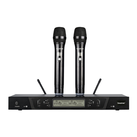
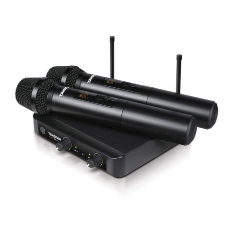
Takstar X6 User manual

User Manual
GUANGDONG TAKSTAR ELECTRONIC CO., LTD.
Address: Longqiao Road Longxi Boluo Huizhou Guangdong China 516121
Tel: +86 752 6383644 Fax: + 86 752 6383952
E-mail: sales@takstar.com
Website: www.takstar.com INTELLIGENT UHF WIRELESS MICROPHONE

※Notice
1
1. Table of Contents…………………………………………………………....................................1
2. Safety Instruction/Features/How to Setup……………………………………….............2-3
3. Function and Operation………………………………………..........................................3-4
4. LCD Panel Instruction………………………………………..............................................4-6
5. Operating Instruction/Correct Usage……………………………………….........................7
6. Trouble Shooting/Maintenance……………………………………………............................8
7. Specification/Product content……………………………………………..............................9
Please read this manual detailedly before using to make
sure the correct operation of this product and exert the best
performance; please also keep this user manual properly
for future needs.
Table of Contents

9 2
Specification
System Specification
Audio Response: 80Hz~18KHz(±3dB)
Frequency Steadiness: <±0.005%
Max. Frequency Deviation: ±45KHz
S/N Ratio: >105dB
Frequency Range: 740~790MHz
Adjustable Range: 50MHz
Frequency Spacing: 250KHz
Dynamic Range: 100dB
THD: ≤0.5% Operating Temperature: -10℃ +40℃
~
Modulation Mode: FM
Number of Channels: 200
Receiver Specification
Receiver Mode: Double conversion superheterodyne
Intermediate Frequency: First: 110 MHz, Second: 10.7MHz
Wireless Interface: TNC/50Ω
Sensitivity Adjustment Range: 12-32dB µ V
Max. Output Level: +10dBV
Sensitivity: 12 dB µ V (80 dB S/N) Spurious Suppression: ≥75 dB
Transmitter Specification
Output Power: <10mW
Power Supply: 2pcs AA battery
Spurious Suppression: -60dB
Playtime: >10hrs
Product Content
Receiver
Handheld microphone
Audio connecting cable
Power adaptor
Antenna
Rack mount
1.5V battery
User manual
1pc
1pc
1pc
1pc
2pcs
2pcs
4pcs
1set
Safety Instruction
Use the supplied power adaptor only and make sure that the AC power voltage is same as the
power adaptor's requirement. The unit may be damaged if other power adaptor is used.
Power supply of this system is AC 220V, fire or malfunction maybe occurred if other voltage is
used.
Do not expose the system to high temperatures, humidity, dust or liquids.
Do not apply any strong shock to it.
Do not dismantle the system. If there are any troubles such as fume or strange smell during
using, please unplug the power adaptor and get in contact with your local retailer for further
checking immediately.
Please place the batteries according to correct polarities. Take out the batteries when not using
it for a long time.
Please do not use batteries with broken or scratched surface, or short circuit may occur.
Please turn off the system and unplug the power adaptor if the system is not used for a long
time.
Features
UHF intelligent wireless audio transmission technology features stable and high interference-free
performance
Advanced frequency scan function features automatical and fast interference-free frequency
selection
Built-in digital frequency assignment system provides more than 100 sets system for engineering
installation
Infrared frequency synchronization technology, LC-display on receiver and transmitter for easy
and convenient operation
Transmitter is powered by 2pcs 1.5V batteries for easy replacement
Balanced and unbalanced output on receiver for convenient connection with various
equipments
Long operating range up to 50 meters
Transmitter housing are treated with alloy oxidation for high ruggedness and against corrosion
How to Setup
It is important to adjust the audio sensitivity properly, too high sensitivity will cause signal
distortion, too low sensitivity will reduce S/N. It is unnecessary to adjust as we have finshed
the adjustment in production.

(1)(2)(2) (3)(4)(3)
DC INPUT ANT B SENSITIVITY B BAL B OUT MIX OUT BAL A OUT SENSITIVITY A
!
CAUTION
RISK OF ELECTRIC SHOCK
DO NOT OPEN
ANT A
(6) (7) (8) (9) (10) (7)(8)(9)
12V 600mA
(5)
3 8
If the frequency is set appropriately, up to 12 transmitters can be used in the same frequency
band; if the frequency is set inappropriately, mutual interference will be caused.
When several systems are used at one venue, please avoid overlapping the receivers.
Receiver Function and Operation
Front Panel
Rear Panel
(1) On/off power switch: press to turn on/off. The LCD lights when it is turned on.
(2) Volume control: adjust the output volume.
(3) Function buttons: adjust frequency, lock the frequency function key and automatically scan
the frequency.
(4) LCD: indicate working status, frequency/channel, squelch, signal level and audio dynamic
level.
(5) Infra-red data synchronization window: transmitting frequency specification signal to
transmitter by pressing “ACT”.
(6) Power socket: connect 12V DC power to the socket. Central electrode of socket connects
positive voltage.
(7) Antenna input socket: connect antennas for longer operating range.
(8) Sensitivity adjustment: the adjustment range is 0-10dB. The smaller value, the lower
sensitivity and shorter distance but with stronger interference rejection capacity, and vice
versa.
(9) Balanced audio output: XLR socket, two independent signal outputs.
(10) Unbalanced audio output: P socket, two mixed signal outputs.
Trouble Shooting
Troubles Possible reasons
No indication on transmitter and
receiver
No RF signal on receiver
With RF signal, but without audio
signal
Running out of batteries or bad connection between
receiver and power supply
Frequency of transmitter and receiver is not the same or
out of operation range
The capsule of transmitter is broken or not well connected;
the squelch of receiver is too high and lead to short
operating range
Background noise of audio
signal is too loud
Audio signal distortion
Operating distance is too short,
signal is not stable
Output level of receiver is too low; there is interference
signal around or antenna on receiver is not installed
Transmitter's modulation frequency deviation is too
high; output level of receiver is too high
Squelch of receiver is too high; receiver antenna is wrongly
placed; there is a strong electro-magnetic interference
around
If there are other troubles, please contact us or your local distributor. Please do not
dismantle the product as it will void warranty.
Maintenance
Do not keep or use the system in high humidity, high electromagnetic or high temperature
environment, please take out the batteries and unplug the power adaptor if not used for a long
time.
Cleaning: please unplug the adaptor before cleaning and clean it with wet cloth. To protect the
do not use any detergent or dissolved liquid.
Power supply: make sure the power supply is within the required range, too high or too low will
affect the performance. Please place the batteries into the transmitter according to correct polarity.
Maintenance: if there are any troubles of the system, please contact your local distributor for
maintenance. Please do not dismantle the products as it will void warranty and be harmful to
yourself.
Accessory: please use the accessories supplied by manufacturer or recognized accessories to exert
the best performance.
Warranty: any dismantling without authorization may lead to cancellation of the warranty.

(1) (2) (3) (4)
(5) (7)
1.
①
②
③
④⑥
⑤
7 4
(6)
Operating Instruction/Correct Usage
A. Do not turn on the transmitter before receiver is powered on. First of all turn the receiver volume
to the minimum. Then press power button for turning on the receiver. After that, background
light of LCD indicator lights and all data as well as receiver channel, frequency and automatic
frequency matching status will display.
B. Before turning on the transmitter, please observe the RF and AF level. If there's strong
interference, please press “SCAN” button for avoiding frequency interference.
C. When the transmitter is turned on, the RF level for corresponding channel will light. Adjust the
receiver to appropriate volume and speak to the microphone, the AF level for corresponding
microphone volume will light. If there is no volume output or level meter doesn’t light, it means
the system is working abnormally and need repair.
D. Long press the power button for 3 seconds, the receiver will be power off.
1. How to use handheld wireless microphone
(1) Hold the middle part of the microphone. Please avoid holding the microphone bottom
where the antenna locates, otherwise, operating distance will be shortened. Please avoid
holding near the wire mesh cap or it will affect the sound pick up effect.
(2) Adjust the distance between microphone and mouth to adjust the tone volume.
2. How to use receiver
(1) The receiver consists of diversity receiver and non-diversity receiver. Non-diversity
receiver is more economic while diversity receiver has longer and better transmission effect.
(2) When receiver adopts omni antenna, the distance between antenna and wall (especially metal)
should be at least 0.5m.
(3) The receiving range is related to many factors with great changes. When there is no large metal
parts obstruct its transmission direction, it will have a better transmission effect.
(4) If the receive condition is unsatisfactory, please use extension cable with external high gain
antenna or even antenna amplifier to achieve obvious distance increasing effect.
(5) When receiver panel is put towards the operating direction or the receiver is built in the metal
case, please connect the antenna to front panel to achieve better receiving effect.
3. How to use several systems at one venue
(1) First, please choose an interference-free RF-frequency. Within 50MHz range, usually 12pcs
of transmitters can be used at the same time. If more sets need to be used at the same time,
please choose other frequency range.
(2) When several transmitters are used at the same time, the distance between transmitters in
different frequencies should be at least 20cm to avoid interference.
(3) When several receivers are used at the same time, it is suggested to install high gain antenna,
antenna amplifier and receiver multi-coupler.
Handheld Microphone Function and Operation
(1) Wire mesh cap and capsule: wire-mesh cap protects the capsule, eliminates pop noise and
prevent rolling.
(2) LCD indicator: indicate channel, battery power and RF power.
(3) Power switch: press to turn on/off the transmitter.
(4) Microphone housing: assemble wire mesh cap and capsule on the top, with battery and PCBA
inside, and antenna at the rear.
(5) Infra-red frequency matching window: transmit frequency specification signal to transmitter by
pressing ACT on receiver.
(6) Tightening screw: protects capsule, prevents the cap and capsule from being disassembled by
non-professional person.
(7) Battery compartment: assemble 2pcs AA batteries.
LCD Panel Instruction
LCD all lights indication
①
②
③
④
⑥
⑤
7-level RF indication: indicates the receiver RF signal strength
7-level power level indication: indicates vocal signal dynamic
Frequency menu: indicates the current frequency
Channel menu: indicates the current channel
Lock indication: indicates the function key lock status
Channel indication: indicates the current channel
B
5mW BAT
5 6
Button function and operation
1) Short press “SCAN” button for automatic frequency scan and “ACT” for automatic frequency
2) Long press “SCAN” for manual adjustment mode, and long press “ACT” for function key locking.
LCD panel instruction
Under the initial interface as picture 1, short press “SCAN” button for automatic channel scan.
When stop scanning, it will finish channel selection.
Under the initial interface as picture 1, long press “SCAN” button, the LED will glitter, indicates
manual frequency adjustment status; Short press or long press “ACT” or “SCAN” button for
adjusting the channel. Once loosen the button, the LED will glitter 5 seconds and stop, it means
channel adjustment is finished.
A. Channel/frequency indication and adjustment
1. Automatic channel scan mode
2. Manual frequency adjustment mode
B. Infrared frequency matching
1. Under the initial interface as picture 1, select the channel, turn on the transmitter and point the
“IR” frequency reception window to the “IR” frequency window on the receiver in line (distance
between transmitter and receiver is 10CM-30CM); short press “ACT” button, the LED indication
as picture 2 will automatically change into the actual frequency/channel display interface after
successfully transmitting the frequency. If it fails, it will show the LED indication as picture 3,
short press “ACT” to continue the frequency matching until it succeeds.
Picture 1
Picture 2 Picture 3
Picture 4 Picture 5
Picture 6
Picture 7
C. System locking
1. Under the initial interface as picture 1, long press “ACT” for function key locking. When locking
is finished, it will show the LED indication as picture 4 and all function key will be locked (except
power button and frequency matching button). Long press “ACT” button for unlocking and it will
show the interface as picture 5.
D. Power off
1. Long press “POWER” for power off and LCD indicator will show the interface as picture 6
E. LCD indicator of microphone
1. When the microphone is powered on, the LCD will light (like picture 7) and it indicates curent
channel, RF strength and battery power level. For changing the channel, please first change the
receiver channel, then point the infrared frequency window of transmitter and receiver to each
other. Then press the “ACT” button on receiver, the new channel specification signal will be
transmitted to the transmitter.
2.
3.
matching.
Other Takstar Microphone manuals

Takstar
Takstar PC K810 User manual

Takstar
Takstar TA-60 User manual

Takstar
Takstar E261W User manual

Takstar
Takstar PH 200 User manual

Takstar
Takstar S360 User manual

Takstar
Takstar BM-630 User manual

Takstar
Takstar SC Series User manual

Takstar
Takstar TS-3380 User manual

Takstar
Takstar DG-K10USB User manual
Takstar
Takstar E-340 User manual

Takstar
Takstar ECM-220 User manual

Takstar
Takstar SM-18 EL User manual

Takstar
Takstar SM-18 PRO User manual

Takstar
Takstar SM-8B-S User manual

Takstar
Takstar TS-8808HH User manual

Takstar
Takstar BM-600 User manual

Takstar
Takstar V4 DUAL User manual

Takstar
Takstar PCM-5600 User manual

Takstar
Takstar GN-900 User manual

Takstar
Takstar PH 125 User manual