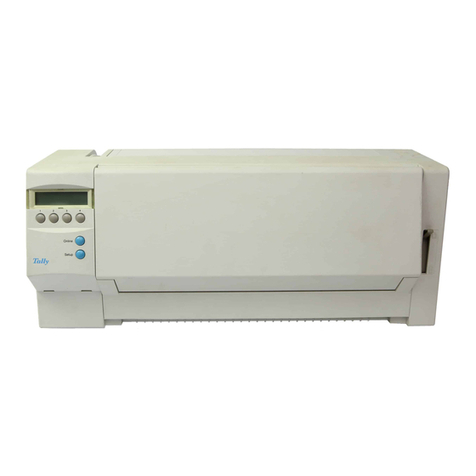
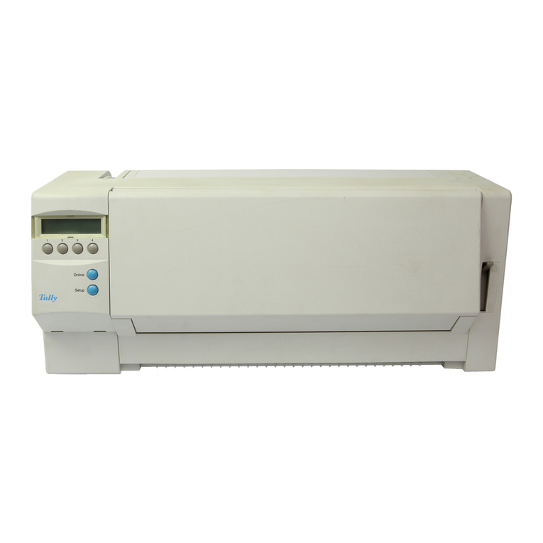
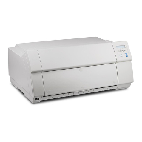
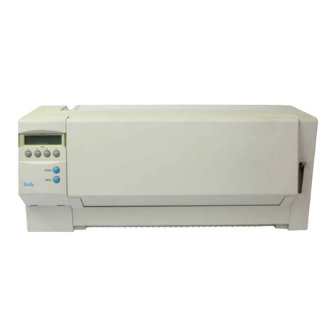
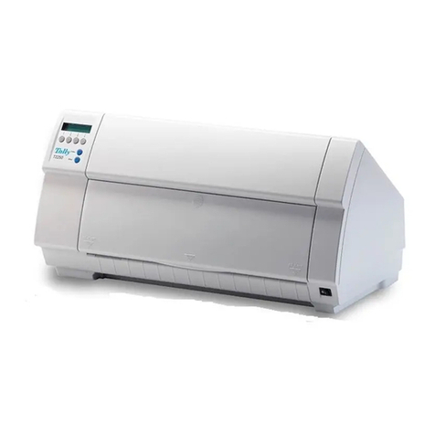
Tally T6140 User manual

T6140
T6141
Maintenance Manual
Impact Line Printer

Appendix A:
Schematics and Illustrated Parts Breakdowns

A–2 T6140/T6141 Maintenance Manual
ILLUSTRATED PARTS LIST
Electronics Assembly T6140/ T6141
Item Part Number Nomenclature Support Qty.
Level
8 078713 Cover Assembly (Back) B 1 Ea
9 076550 Support Assembly (Front) B 1 Ea
11 076875 Nozzle, Air B 1 Ea
15 075492 Seal, Blower B 1 Ea
16 076915 Seal, Capacitor B 1 Ea
17 730717 Capacitor - 60,000 MFd 80V A 1 Ea
18 400292-08 Clamp, Capacitor B,C 1 Ea
19 400065-06 Strain Relief, Cable B,C 1 Ea
20 081653 Logic PC Assembly A 1 Ea
21 402987-01 Label, High Voltage B 1 Ea
22 402997-01 Label, Fuse Warning B 1 Ea
23 080958 Label, Warning 70V Circuit B 1 Ea
24 403728-01 Guide, Card B,C 3 Ea
25 402524-41 Screw, #8-32 x 0.25 SEMS(T6140) B,C 2 Ea
26 402524-29 Screw, #6-32 x 0.44 SEMS B,C 9 Ea
27 402524-63 Screw, #10-32 x 0.50 SEMS B,C 2 Ea
28 402524-03 Screw, #4-40 x 0.50 SEMS B,C 2 Ea
29 402524-01 Screw, #4-40 x 0.25 SEMS B,C 3 Ea
30 076916 Label, Connector Identification B 1 Ea
31 400216-07 Washer, #4 Flat B,C 3 Ea
32 402524-24 Screw, #6-32 x 0.75 SEMS B,C 1 Ea
33 730382 Nut, #6-32 Hex Keps B,C 1 Ea
34 078487 Interface, Serial / Parallel PCA A 1 Ea
35 079251 Gasket, Air Seal (T6140) B 1 Ea
36 078065 Foam, Cable Exit (T6140) B 1 Ea
38 078063 Foam, Cable Exit B 1 Ea
39 078064 Foam, Cable Exit B 2 Ea
Item Part Number Nomenclature Support Qty.
Level
40 078399 Module, Personality
(Serial/Parallel) A 1 Ea
42 400693-52 Screw, #6-32 x 5/16 Flat Head,
Phillips 82°B,C 2 Ea
43 730628 Clamp, Cable - Flat Mount B,C 2 Ea
44 078467 Label, Warning - Electronics Cover B 1 Ea
45 730951 Ground Strap, Insulated (T6140) B 1 Ea
46 730958 Washer 3/4 inch diameter,
Flat (T6140) B,C 3 Ea
47 732211 Ferrite - 2.50 “ Wide B,C 4 Ea
48 730210 Ferrite - 3.00" Wide B,C 4 Ea
51 Clamp - Cable, Twist Lock B,C 2 Ea
53 Nut - #8 Hex, KEPS (T6140) B,C 2 Ea
56 Screw, #8-32 x 0.75 SEMS B,C 1 Ea
57 080597 Bracket, Ferrite Support B 1 Ea
60 082048 Power Supply Assembly A 1 Ea
61 080190 Panel Assembly, AC Power
Switch (T6140) B 1 Ea
61 080191 Panel Assembly, AC Power
Switch (T6141) B 1 Ea
64 076213 Cover, Power Input Panel B 1 Ea
65 605318-2 Label, Ground Symbol B 1 Ea
66 400783-01 Nut, #4-40 Hex, KEPS B,C 4 Ea
Appendix A: Schematics and Illustrated Parts Breakdowns A–3
To Blower Assembly
Electronics Assembly
26
Front Panel J801
Platen Open J601
Paper Out J602
Paper Motion J603
Shuttle Capture J604
Shuttle Motor J501
Ribbon Motor J502
Paper Motor J503
J901
44
35
36
9
24
11
28
65
29
31
18
15
30
8
34
21
40
32 33
60
26
17
16
27
40
42
4x
2x
39
2x
2x
38
43
2x
3x
3x
6x
19
0.6
20
57
47
48/49

A–4 T6140/T6141 Maintenance Manual
ILLUSTRATED PARTS LIST
Frame Assembly T6140/ T6141
Item Part Number Nomenclature Support Level Qty.
9 079030 Base Assembly (T6140) B 1 Ea
9 079225 Base Assembly (T6141) B 1 Ea
11 078433 Support, Platen B 1 Ea
12 078290 Frame B 1 Ea
13 611219-1 Foam, Upper B 1 Ea
14 078318 Foam, Platen - Right B 1 Ea
15 611219-3 Foam, Center - Lower B 1 Ea
16 611219-4 Foam, Lower B 1 Ea
17 611219-5 Foam, Center - Upper B 1 Ea
18 078319 Foam, Platen - Left B 1 Ea
19 078317 Damper, Platen Support B 1 Ea
21 611096-1 Plate, Detent - Platen Lever B 1 Ea
23 075135 Cable Assy., Platen Open B 1 Ea
24 075141 Cap - Duct, Air Inlet (T6140) B 1 Ea
25 611414-1 Ground Strap Assembly, 3,35 Lg(T6140) B 1 Ea
27 079783 Label, S/N Supplemental (T6141) B 1 Ea
28 403769-09 Mount, Vibration Damping (T6140) B,C 1 Ea
29 079495 Blower Assy (Fan) A 1 Ea
32 732209 Screw, Set 1/4-20 x 0.625 B,C 1 Ea
33 402524-42 Screw, 8-32 x 0.38 SEMS (T6140) B,C 1 Ea
34 402524-43 Screw, 8-32 x 0.50 SEMS B,C 3 Ea
35 730797 Screw, 10-32 x 0.38 SEMS w/ Int. star (T6141) B,C 2 Ea
36 400995-20 Washer, Curved Spring B,C 2 Ea
37 400918-05 Washer, Flat 0.030 Thk. (T6140) B,C 2 Ea
38 400918-10 Washer, Flat 0.062 Thk. B,C 2 Ea
39 400069-03 Washer, #8 External Star B,C 1 Ea
40 611414-3 Ground Strap Assembly, 6" Lg (T6141) B 1 Ea
43 081860 Platen Assembly A 1 Ea
44 081090 Pin - Platen Support B,C 2 Ea
45 400689-73 Set Screw, 10-32 x 0.31 Socket HD B,C 2 Ea

Appendix A: Schematics and Illustrated Parts Breakdowns A–5
Frame Assembly
36
36
32
22
16
18
11 19
23
34
12 20
25 34 38
24
29
39
9
34
33
37
28
30
21
22
17
15
14
13
REF
2x
2x
33

A–6 T6140/T6141 Maintenance Manual
ILLUSTRATED PARTS LIST
Hammer Bank and Shuttle T6140/ T6141
Item Part Number Nomenclature Support Level Qty.
10 078368 Hammer Bank and Ribbon Shield Assy. A 1 Ea
10A 078370 Hammer Module 6-pack, Odd (Lower) A 11 Ea
10B 078371 Hammer Module 6-pack, Even (Upper) A 11 Ea
10C 079494 Ribbon Shield Set A 1 Ea
11 081612 Shuttle Module Assembly A 1 Ea
12 078455 Stabilizer and BracketAssembly B 1 Ea
13 078955 Bridge B 1 Ea
14 611478-1 Support, L.H. Bearing Block B 1 Ea
15 076900 Bearing Block Assy.,Left (Complete) B 1 Ea
18 730007 Belt, Shuttle Drive A 1 Ea
19 078259 Motor, Shuttle Drive A 1Ea
22 730768 Washer, #10 Split lock, High Strength B,C 1 Ea
23 400866-05 Screw, 10-32 x 0.50 Socket Hd. B,C 1 Ea
25 730910 Bead - Ferrite, Clamp On B,C 1 Ea
27 402524-23 Screw, 6-32 x .50 SEMS B,C 2 Ea
28 402524-24 Screw, 6-32 x .75 SEMS B,C 1 Ea
29 075146 Sensor, Shuttle Position A 1Ea
30 402524-43 Screw, 8-32 x .50 SEMS B,C 2 Ea
31 402524-44 Screw, 8-32 x .75 SEMS B,C 4 Ea
32 402524-51 Screw, 8-32 x .62 SEMS B,C 1 Ea
33 078936 Plate, Flexure Clamp B 4 Ea
34 078937 Adaptor, Stabilizer Bracket B 1 Ea
36 078039 Flexure, Right B 1 Ea
37 078933 Bracket, Left flexure mounting B 1 Ea
38 078934 Bracket, Carriage flexure mounting B 1 Ea
39 078935 Flexure, Left B 1 Ea
41 730381 Screw, 6-32 x 3/8 SEMS B,C 3 Ea
42 400693-52 Screw, 6-32 x 5/16 Flat head B,C 2 Ea
44 402524-45 Screw, 8-32 x 1 SEMS B,C 1 Ea
45 402524-27 Screw, 6-32 x 5/16 SEMS B,C 1 Ea

Appendix A: Schematics and Illustrated Parts Breakdowns A–7
Hammer Bank and Shuttle
31
8
25
27
44
38
34
33
33 41
41
32
30
39 38
45
33
31
22
23
12
18
19
30
Shuttle Sensor Adjustment
(0.20 ±0.50)
15°±5°)
15
14
28
11
10
37
27
41
42
2x
13
31
29

A–8 T6140/T6141 Maintenance Manual
ILLUSTRATED PARTS LIST
Paper Drive Assembly T6140/ T6141
Item Part Number Nomenclature Support Level Qty.
10 081872 Tractor Assembly w/ Sensor (lower) A 1 Ea
11 081873 Tractor Assembly w/ Sensor (upper) A 1 Ea
12 078033 Paper Motor Assembly A 1 Ea
14 075482 Shaft, Paper Drive (Square Shaft) B 2 Ea
15 075483 Shaft, Tractor Support (Round Shaft) B 2 Ea
16 075480 Bushing, Square Shaft B 2 Ea
17 080635 Pulley, Paper Drive B 2 Ea
18 081498 Belt, Paper Drive A 2 Ea
19 075129 Retainer, Bearing B 4 Ea
20 075130 Support, Ribbon Platform B 2 Ea
21 602631-1 Spring, Idler B,C 6 Ea
22 075477 Idler B 4 Ea
23 730094 Bearing B 4 Ea
24 400641-18 Grip Ring - 0.50 O.D. B,C 4 Ea
26 075126 Paper Tensioning Assembly B 1 Ea
27 075134 Lever, Phasing Adjust B 1 Ea
29 075122 Idler Assembly, Lower B 1 Ea
32 403738-01 Plunger, Spring B 1 Ea
33 730095 Bearing, Nylon Flanged B 1 Ea
35 400995-16 Washer, Curved Spring B,C 1 Ea
36 402524-41 Screw, 8-32 x 0.25 SEMS (T6140) B,C 2 Ea
37 402524-05 Screw, 4-40 x 1.00 SEMS B,C 2 Ea
38 402524-42 Screw, 8-32 x 0.38 SEMS B,C 2 Ea
39 402524-43 Screw, 8-32 x 0.50 SEMS B,C 4 Ea
40 402524-48 Screw, 8-32 x 0.875 SEMS B,C 4 Ea
41 402524-51 Screw, 8-32 x 0.625 SEMS B,C 4 Ea
42 401417-06 Terminal, Rect. Tonque 0.250 (T6140) B,C 1 Ea
61 081656 Spacer - Pulley B 2 Ea

Appendix A: Schematics and Illustrated Parts Breakdowns A–9
Paper Drive Assembly
27
3x
2x
4x
2x
2x
33
32
8
39
35
35
11
36 12
46
16
41
11
15
4x
19
2x
20
4x
23
2x
2x
10
21
10
14
37
4x
6x
2x
24
4x
22 4x
40
27
17
2x
18
26
29
39
3813
61

A–10 T6140/T6141 Maintenance Manual
ILLUSTRATED PARTS LIST
Ventilation Components T6140/ T6141
Item Part Number Nomenclature Support Level Qty.
9 078511 Cable and Bracket Assembly A 1 Ea
10 078748 Duct, Interconnect B 1 Ea
11 076831 Duct, Hammerbank B 1 Ea
13 078182 Brace, Cable Support B 1 Ea
16 730268 Clamp, Cable Flat Mount B,C 2 Ea
18 402524-27 Screw, 6-32 x 0.312 SEMS B,C 6 Ea
19 730024 Clamp, Hose (Black) B,C 1 Ea
20 402524-47 Screw, 8-32 x 0.312 SEMS B,C 1 Ea
21 400693-52 Screw, 6-32 x .312 Flat head Phillips 82°B,C 2 Ea
22 402524-21 Screw, 6-32 x 0.25 SEMS B,C 3 Ea
23 730381 Screw, 6-32 x 0.38 SEMS B,C 4 Ea

Appendix A: Schematics and Illustrated Parts Breakdowns A–11
Ventilation Components
13
6x
3x
18
22
4x
20
16
9
11
19
10
23
21

A–12 T6140/T6141 Maintenance Manual
ILLUSTRATED PARTS LIST
PRINT MECHANISM T6140/ T6141
Item Part Number Nomenclature Support Level Qty.
5 076868 Ribbon Platform, Complete B 1 Ea
10 076867 Bracket, Support (lower) B 1 Ea
11 079832 Platform Assy (upper) B 1 Ea
11A 075138 Motor, Ribbon Drive A 1 Ea
12 079243 Disk Mounting, Rib Mot Sensor (Option) B 1 Ea
13 731002 Sensor - Motion, Photointerruptor (Option) B 1 Ea
14 079246 Cable Assy - Rib Mot Sensor (Option) B 1 Ea
15 402953-01 Pad, Cable Mounting B,C 1 Ea
17 402524-43 Screw, 8-32 x .50 SEMS B,C 6 Ea
18 730381 Screw,6-32 x .38 SEMS B,C 2 Ea
19 400693-70 Screw. 8-32 x 0.5, 82°Flat Head Phillips B,C 4 Ea
079963 Brush-Anti-Static B 1 Ea

Appendix A: Schematics and Illustrated Parts Breakdowns A–13
Print Mechanism
4x
10
17
2x
11
17
18

A–14 T6140/T6141 Maintenance Manual
ILLUSTRATED PARTS LIST
COVER / LID ASSEMBLY T6140
Item Part Number Nomenclature Support Level Qty.
1 078049 Cover Assembly A 1Ea
2 078049 Lid Assembly A 1Ea
3 075154 Base Assembly A 1Ea
8 075487 Lid, Standard Color B 1Ea
9 075486 Cover, Molded B 1Ea
10 075145 Window, Lid A 1Ea
11 Seal, Lid Rear B 1Ea
12 611249-1 Trim, Widow B 1Ea
13 078534 Paper Guide, Upper Top B 1Ea
14 611190-2 Foam, Paper Guide Upper Top B 1Ea
15 078533 Paper Guide Upper Bottom B 1Ea
16 611190-1 Foam, Paper Guide Upper Bottom B 1Ea
18 080017 Support (Hinge), Lid Left Side A 1Ea
19 080018 Support (Hinge), Lid Right Side A 1Ea
20 402524-42 Screw, SEMS 8-32x3/8 B,C 12Ea
21 078621 Handle & Seal Assy., Lid B 1Ea
23 611472-1 Label, Paper Tension B 1Ea
24 611471-1 Label, Platen Gap Setting B 1Ea
25 611466-1 Seal, Lid B 1Ea
26 611466-2 Seal, Lid B 1Ea
27 611466-3 Seal, Lid B 1Ea
28 611466-4 Seal, Lid B 1Ea
31 075183 Latch, Cover A 2Ea

Appendix A: Schematics and Illustrated Parts Breakdowns A–15
CPI
2LPI
3MODE
FORMS
1CLEAR ENTER
TOF
VIEW FF
LF ONLINE
OFFLINE
ONLINE
POWER
FAULT
18
28
26
21
12 10
13
25
27
14
16
15 20
4x
2
20
4x
11
19
2x
20
23
2x
20
24
Cover / Lid Assembly
T6140 Only
This manual suits for next models
1
Table of contents
Other Tally Printer manuals

Tally
Tally T2150 User manual

Tally
Tally Tally Mono Laser T9220 User manual

Tally
Tally T 2045 User manual

Tally
Tally T2040 User manual

Tally
Tally T6215 User manual

Tally
Tally T2030 User manual

Tally
Tally T6090 User manual

Tally
Tally T2265plus User manual

Tally
Tally DT-230 User manual

Tally
Tally T2150 User manual

Tally
Tally T9312 User manual

Tally
Tally T9114 User manual

Tally
Tally T2265 SprintPro User manual

Tally
Tally XPRESS T9412i User manual

Tally
Tally T7070 User manual

Tally
Tally T9114 Installation guide

Tally
Tally T3016 User manual

Tally
Tally Dascom 1125 User manual

Tally
Tally T8024 User manual

Tally
Tally T2033S User manual